26892 Results
Level of archival description:
Project
Project
Actions:
Reference number:
AP018.S1.1954.PR01
Description:
This project series documents the Imperial Oil office and research building in Sarnia, Ontario from 1954-1955. The office identified the project number as 5421. This project consisted of a two storey building with a basement to be used by the engineering division of Imperial Oil. It contained offices, research areas, a library, a drawing and data files area, a printing department and an electronic computation area. Located on the corners of Christina and St. Andrew Streets, the building was 53,000 square feet in size and located on a 75,000 square foot lot. Structurally, the offices had a steel framework enclosed with glass and porcelain enamel on aluminum panels. A round auditorium connected to the main structure was faced in deep plum brick. The project is recorded through reprographic copies of construction drawings dating from 1954-1955.
People:
Date:
1954 - 1955
1954 - 1955
Title:
Office Building for Imperial Oil Ltd., Sarnia, Ontario (1954-1955)
Actions:
AP018.S1.1954.PR01
Description:
This project series documents the Imperial Oil office and research building in Sarnia, Ontario from 1954-1955. The office identified the project number as 5421. This project consisted of a two storey building with a basement to be used by the engineering division of Imperial Oil. It contained offices, research areas, a library, a drawing and data files area, a printing department and an electronic computation area. Located on the corners of Christina and St. Andrew Streets, the building was 53,000 square feet in size and located on a 75,000 square foot lot. Structurally, the offices had a steel framework enclosed with glass and porcelain enamel on aluminum panels. A round auditorium connected to the main structure was faced in deep plum brick. The project is recorded through reprographic copies of construction drawings dating from 1954-1955.
Level of archival description:
Project
Project
Date:
1954 - 1955
1954 - 1955
People:
Form:
textual records
textual records
Title:
LRHD
LRHD
Reference number:
ARCH153578
Description:
Handwritten minutes of meeting, 6 April 1973 Memos from PDE, Peter Wolf Complaint letter to PDE from Kenneth Frampton, April 23 1972 Estimates for exhibition catalog Proposals and description of the structure of MoMA exhibition Budget Newspaper clippings, Newsdays, July 18 1973 Several project descriptions & cost analyses
People:
Date:
1972-1973
1972-1973
Title:
LRHD
Actions:
ARCH153578
Description:
Handwritten minutes of meeting, 6 April 1973 Memos from PDE, Peter Wolf Complaint letter to PDE from Kenneth Frampton, April 23 1972 Estimates for exhibition catalog Proposals and description of the structure of MoMA exhibition Budget Newspaper clippings, Newsdays, July 18 1973 Several project descriptions & cost analyses
Form:
textual records
textual records
Date:
1972-1973
1972-1973
People:
Form:
textual records
textual records
Actions:
Reference number:
DR1999:0500
Description:
documents include 20 photographs, reviews, notes, acoustics, area summary, project directory, elevations, specifications, zoning, code, washrooms, floor finishes, plans, doors, hinges, locks, structure, interior, ticket booth, drawings: foundation, skylights, windows, plumbing, computer drawings: elevations, floor and roof plans, artifact (foamcore), trade catalogues, miscellaneous blueprints and drawings, correspondence
People:
Title:
Photographs, reviews, notes, acoustics, area summary, project directory, elevations
Actions:
DR1999:0500
Description:
documents include 20 photographs, reviews, notes, acoustics, area summary, project directory, elevations, specifications, zoning, code, washrooms, floor finishes, plans, doors, hinges, locks, structure, interior, ticket booth, drawings: foundation, skylights, windows, plumbing, computer drawings: elevations, floor and roof plans, artifact (foamcore), trade catalogues, miscellaneous blueprints and drawings, correspondence
Form:
textual records
textual records
People:
Form:
drawings
drawings
Actions:
Reference number:
DR1994:0006:007
Description:
- The perspective sketch corresponds with the rough plan, which shows the two wings of the court house and the courtyard. The perspective drawing appears to have been drawn after the plan, which may reflect the architect's approach to the problem: drawing the plan and then working out the relationship between the structure to the site.
People:
Date:
1934
1934
Title:
Sketch perspective and sketch plan for Mountain House
Actions:
DR1994:0006:007
Description:
- The perspective sketch corresponds with the rough plan, which shows the two wings of the court house and the courtyard. The perspective drawing appears to have been drawn after the plan, which may reflect the architect's approach to the problem: drawing the plan and then working out the relationship between the structure to the site.
Form:
drawings
drawings
Date:
1934
1934
People:
Level of archival description:
Project
Project
Title:
Circlorama
Circlorama
Reference number:
AP144.S2.D51
Description:
File documents proposals for a portable circular cinema for Circlorama Theatres Limited, of London, England, United Kingdom. Thumbnail sketches show positioning of concrete bases; erection of the cinema, central tower, and trussed wall frames; and the installation of the radially-trussed roof, interior fixtures, and exterior aluminum cladding. Diagrammatic sections show alternate designs for the structure and structural systems. A flow diagram illustrates projected circulation patterns. Also included in the group are fabrication drawings for the cinema by various consultants which Price may have used for reference purposes. Material in this file was produced between 1962 and 1964. File contains drawings by the following firms: Lawrence Colebrook (Construction Equipment) Co. Ltd, Andrew Smith Harkness Ltd, Cotton Ballard & Blow Architects & Surveyors. File contains design development drawings and textual records.
People:
Date:
1962-1964, 1967
1962-1964, 1967
Title:
Circlorama
Actions:
AP144.S2.D51
Description:
File documents proposals for a portable circular cinema for Circlorama Theatres Limited, of London, England, United Kingdom. Thumbnail sketches show positioning of concrete bases; erection of the cinema, central tower, and trussed wall frames; and the installation of the radially-trussed roof, interior fixtures, and exterior aluminum cladding. Diagrammatic sections show alternate designs for the structure and structural systems. A flow diagram illustrates projected circulation patterns. Also included in the group are fabrication drawings for the cinema by various consultants which Price may have used for reference purposes. Material in this file was produced between 1962 and 1964. File contains drawings by the following firms: Lawrence Colebrook (Construction Equipment) Co. Ltd, Andrew Smith Harkness Ltd, Cotton Ballard & Blow Architects & Surveyors. File contains design development drawings and textual records.
Level of archival description:
File 51
File 51
Date:
1962-1964, 1967
1962-1964, 1967
People:
Form:
drawings
drawings
Reference number:
DR1966:0001:012
Description:
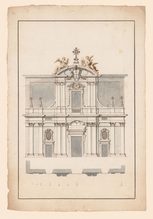
- This elevation and plan are for the façade of a church. The façade is composed of two stories; the upper story is narrower than the bottom and it has walls set back on either side. On the left and right sides an alternative design (or a record of the interior structure) is sketched in with pen and brown ink.
DR1966:0001:012
Description:
- This elevation and plan are for the façade of a church. The façade is composed of two stories; the upper story is narrower than the bottom and it has walls set back on either side. On the left and right sides an alternative design (or a record of the interior structure) is sketched in with pen and brown ink.
People:
Subject:
architecture
architecture
Date:
ca. 1720
ca. 1720
Title:
Elevation and plan of the façade of the church of S. Adriano, Rome
Actions:
DR1966:0001:012
Description:
- This elevation and plan are for the façade of a church. The façade is composed of two stories; the upper story is narrower than the bottom and it has walls set back on either side. On the left and right sides an alternative design (or a record of the interior structure) is sketched in with pen and brown ink.
Form:
drawings
drawings
Date:
ca. 1720
ca. 1720
People:
Subject:
architecture
architecture
Level of archival description:
Project
Project
Title:
Britail
Britail
Actions:
Reference number:
AP144.S2.D131
Description:
File documents a set of proposals to British Railways for improvements to their passenger railway stations. Price's proposals included the use of pre-fabricated structures as shelters around the stations; the improvement of landscaping around the stations; new furniture and fittings; the improvement of services such as heating, electronic signage and station announcement mechanisms; the cleaning and painting of surfaces; and the increased presence of information and graphical devices in the stations. Material in this file was produced between 1984 and 1991. File contains reference drawings, photographic materials, and textual records.
People:
Date:
1984-1991
1984-1991
Title:
Britail
Actions:
AP144.S2.D131
Description:
File documents a set of proposals to British Railways for improvements to their passenger railway stations. Price's proposals included the use of pre-fabricated structures as shelters around the stations; the improvement of landscaping around the stations; new furniture and fittings; the improvement of services such as heating, electronic signage and station announcement mechanisms; the cleaning and painting of surfaces; and the increased presence of information and graphical devices in the stations. Material in this file was produced between 1984 and 1991. File contains reference drawings, photographic materials, and textual records.
Level of archival description:
File 131
File 131
Date:
1984-1991
1984-1991
People:
Level of archival description:
Project
Project
Actions:
Reference number:
AP194.S1.1995.PR01
Description:
Project records consist of records documenting the three phases of the Synthetic Landscape project (1995-2000) as worked on by Johan Bettum and OCEAN North. The project was initially developed and submitted in 1995 for the Membrane Design International Competition held in Japan by the Taiyo Kogyo Corporation. The entry showcases a children’s playscape in the setting of Oslo’s Tøyen Park, joining both its urban surroundings and its natural landscape into a synthetic space. Afterwards, the project was exhibited at the Architecture Association (AA) in London, where Johan Bettum and Kivi Sotamaa met. This eventually led to Bettum and Sotamaa collaborating on projects, along with their respective OCEAN teams in Oslo and Helsinki. The Synthetic Landscape project continued as a research project, with a second phase in 1996 and a third phase which ran from 1997 through 2000 and integrated design methods (particle streaming, Channelling Systems) from the work made on the Töölö and Jyväskylä projects. In the third phase, a pavilion was also added to the setting. Aside from one drawing, all records for this project are in a digital format. Drawings and models from phase 1 show parts or the whole of a shell-like structure. A color scheme seems to be associated to the different components of the structure. A report on phases 1 and 2 discusses the use of synthetic and composite materials for the structure, explaining the concept for the site. Phase 2 textual records include a working plan, site charts and program. Additional drawings and models show an evolution in the shape of the landscape. Most records are related to the third phase of Synthetic Landscape. They are largely drawings and models showing textures and coloured grafts used in the design process, section and surfaces studies, as well as site plans. Other files of the third phase consist of animated renderings of Channelling Systems studies within the Synthetic Landscape topology, saved as Quicktime MOV files. Additionally, the third phase of Synthetic Landscape has files related to the FEM (finite element method) analysis process utilized in the project’s engineering. This particular section includes raster images showing vectorial drawings and data appearing to be surface studies. These were likely created with the software Mathematica. The bulk of textual documentation on the project’s scope and outcomes may be found in AP194.S1.1995.PR01.001 for phases 1 and 2, and in AP194.S1.1995.PR01.005 for phase 3. The latter file also contains documentation related to a grant application to The Research Council of Norway; a proposal for a conference and exhibition at the AA; and administrative records such as budgets, correspondence, invoices, progress reports, meeting agendas and minutes. For all project phases, records related to the design process consist of CAD models saved in a variety of modelling formats (iges, fmz, dgn, 3dm, dxf) as well as raster or vector images (tiff, jpeg, png, eps, pict, etc.). In some cases, only these raster or vector images of the original CAD drawings are present in the archive.
People:
Date:
1995-2000
1995-2000
Title:
Synthetic Landscape research project, Oslo, Norway (1995-2000)
Actions:
AP194.S1.1995.PR01
Description:
Project records consist of records documenting the three phases of the Synthetic Landscape project (1995-2000) as worked on by Johan Bettum and OCEAN North. The project was initially developed and submitted in 1995 for the Membrane Design International Competition held in Japan by the Taiyo Kogyo Corporation. The entry showcases a children’s playscape in the setting of Oslo’s Tøyen Park, joining both its urban surroundings and its natural landscape into a synthetic space. Afterwards, the project was exhibited at the Architecture Association (AA) in London, where Johan Bettum and Kivi Sotamaa met. This eventually led to Bettum and Sotamaa collaborating on projects, along with their respective OCEAN teams in Oslo and Helsinki. The Synthetic Landscape project continued as a research project, with a second phase in 1996 and a third phase which ran from 1997 through 2000 and integrated design methods (particle streaming, Channelling Systems) from the work made on the Töölö and Jyväskylä projects. In the third phase, a pavilion was also added to the setting. Aside from one drawing, all records for this project are in a digital format. Drawings and models from phase 1 show parts or the whole of a shell-like structure. A color scheme seems to be associated to the different components of the structure. A report on phases 1 and 2 discusses the use of synthetic and composite materials for the structure, explaining the concept for the site. Phase 2 textual records include a working plan, site charts and program. Additional drawings and models show an evolution in the shape of the landscape. Most records are related to the third phase of Synthetic Landscape. They are largely drawings and models showing textures and coloured grafts used in the design process, section and surfaces studies, as well as site plans. Other files of the third phase consist of animated renderings of Channelling Systems studies within the Synthetic Landscape topology, saved as Quicktime MOV files. Additionally, the third phase of Synthetic Landscape has files related to the FEM (finite element method) analysis process utilized in the project’s engineering. This particular section includes raster images showing vectorial drawings and data appearing to be surface studies. These were likely created with the software Mathematica. The bulk of textual documentation on the project’s scope and outcomes may be found in AP194.S1.1995.PR01.001 for phases 1 and 2, and in AP194.S1.1995.PR01.005 for phase 3. The latter file also contains documentation related to a grant application to The Research Council of Norway; a proposal for a conference and exhibition at the AA; and administrative records such as budgets, correspondence, invoices, progress reports, meeting agendas and minutes. For all project phases, records related to the design process consist of CAD models saved in a variety of modelling formats (iges, fmz, dgn, 3dm, dxf) as well as raster or vector images (tiff, jpeg, png, eps, pict, etc.). In some cases, only these raster or vector images of the original CAD drawings are present in the archive.
Level of archival description:
Project
Project
Date:
1995-2000
1995-2000
People:
Form:
archives
Level of archival description:
Fonds
archives
Level of archival description:
Fonds
Title:
Paul-Philippe Cret fonds
Paul-Philippe Cret fonds
Actions:
Reference number:
AP031
Synopsis:
Paul-Philippe Cret fonds, 1907-1950, documents Cret’s project for the International Bureau of American Republics (Pan American Union Building) in Washington D.C. (1907 – 1950). The fond is comprised of drawings showing plans, elevations, wiring and plumbing diagrams, and furniture layout.
People:
Date:
circa 1907-1950
circa 1907-1950
Title:
Paul-Philippe Cret fonds
Actions:
AP031
Synopsis:
Paul-Philippe Cret fonds, 1907-1950, documents Cret’s project for the International Bureau of American Republics (Pan American Union Building) in Washington D.C. (1907 – 1950). The fond is comprised of drawings showing plans, elevations, wiring and plumbing diagrams, and furniture layout.
Form:
archives
Level of archival description:
Fonds
archives
Level of archival description:
Fonds
Date:
circa 1907-1950
circa 1907-1950
People:
Level of archival description:
Sub-series
Sub-series
Title:
Drawings and scripts
Drawings and scripts
Actions:
Reference number:
AP165.S7.SS1
Description:
The Drawings and scripts sub-series, 1980 – 2000, consists of 2538 digital files (2 GB) that document Hoberman’s work in AutoCAD to create his patented transformable designs. The majority of records are AutoCAD drawing files and AutoLISP scripts, dating from the mid to late 1990s. Drawings in the sub-series comprise a variety of Hoberman’s expanding installations, toy products and architectural structures, as well as a series of industrial patents and production drawings that detail the manufacturing and assembly of parts. AutoLISP scripts included in the sub-series were written and used by Hoberman for customized command within the AutoCAD environment as the in-program language. These scripts allowed Hoberman to solve the complex mathematical and geometrical calculations necessary to control the design and engineering of each component of his structures. Notable projects include: Iris Dome at Expo 2000 World's Fair, Hanover (2000); Expanding Hypar at California Science Center, Los Angeles (1998); Expanding Helicoid at Inventor's Hall of Fame, Akron (1998); Expanding Fabric Dome at Centre Georges Pompidou, Paris (1997); Iris Dome at Museum of Modern Art, New York (1994); Geodesic Sphere at Technorama der Shweiz, Winterthur (1993); and Expanding Sphere at Liberty Science Center, Jersey City (1991).
People:
Date:
1980 - 2000
1980 - 2000
Title:
Drawings and scripts
Actions:
AP165.S7.SS1
Description:
The Drawings and scripts sub-series, 1980 – 2000, consists of 2538 digital files (2 GB) that document Hoberman’s work in AutoCAD to create his patented transformable designs. The majority of records are AutoCAD drawing files and AutoLISP scripts, dating from the mid to late 1990s. Drawings in the sub-series comprise a variety of Hoberman’s expanding installations, toy products and architectural structures, as well as a series of industrial patents and production drawings that detail the manufacturing and assembly of parts. AutoLISP scripts included in the sub-series were written and used by Hoberman for customized command within the AutoCAD environment as the in-program language. These scripts allowed Hoberman to solve the complex mathematical and geometrical calculations necessary to control the design and engineering of each component of his structures. Notable projects include: Iris Dome at Expo 2000 World's Fair, Hanover (2000); Expanding Hypar at California Science Center, Los Angeles (1998); Expanding Helicoid at Inventor's Hall of Fame, Akron (1998); Expanding Fabric Dome at Centre Georges Pompidou, Paris (1997); Iris Dome at Museum of Modern Art, New York (1994); Geodesic Sphere at Technorama der Shweiz, Winterthur (1993); and Expanding Sphere at Liberty Science Center, Jersey City (1991).
Level of archival description:
Sub-series 1
Sub-series 1
Date:
1980 - 2000
1980 - 2000
People: