26892 Results
Level of archival description:
Project
Project
Actions:
Reference number:
AP018.S1.1974.PR14
Description:
This project series documents the addition of offices to the research building of Abitibi Power and Paper Company Ltd in Mississauga, Ontario. The office identified the project number as 7416. The project is recorded through drawings and textual records dating from 1974-1980. The majority of the drawings are reprographic copies that show site plans, floor plans, elevations, and structures. Textual records include correspondence with client, contractors, sub-contractors, and consultants, meetings and inspection reports, and change orders. Box AP018.S1.1974.PR14.009 includes an index to the textual records created by the office. The project series also includes a microfilmed version of the contract documents.
People:
Date:
1974-1980
1974-1980
Title:
Abitibi Power and Paper Company Ltd, Office addition to research building, Mississauga, Ontario (1974)
Actions:
AP018.S1.1974.PR14
Description:
This project series documents the addition of offices to the research building of Abitibi Power and Paper Company Ltd in Mississauga, Ontario. The office identified the project number as 7416. The project is recorded through drawings and textual records dating from 1974-1980. The majority of the drawings are reprographic copies that show site plans, floor plans, elevations, and structures. Textual records include correspondence with client, contractors, sub-contractors, and consultants, meetings and inspection reports, and change orders. Box AP018.S1.1974.PR14.009 includes an index to the textual records created by the office. The project series also includes a microfilmed version of the contract documents.
Level of archival description:
Project
Project
Date:
1974-1980
1974-1980
People:
Form:
photographs
photographs
Title:
Views of two models
Views of two models
Reference number:
AP140.S2.SS1.D29.P6
Description:
views of two models, one being a site model in wood (not otherwise present in project documents) that shows an earlier design for the service and circulation towers of the office building, the other being a more detailed model for what is probably the final design that shows the office building in section with the external steel structure and splayed glass wall of the front elevation
People:
Title:
Views of two models
Actions:
AP140.S2.SS1.D29.P6
Description:
views of two models, one being a site model in wood (not otherwise present in project documents) that shows an earlier design for the service and circulation towers of the office building, the other being a more detailed model for what is probably the final design that shows the office building in section with the external steel structure and splayed glass wall of the front elevation
Form:
photographs
photographs
People:
Form:
photographs
photographs
Title:
Views of two models
Views of two models
Actions:
Reference number:
AP140.S2.SS1.D29.P7
Description:
views of two models, one being a site model in wood (not otherwise present in project documents) that shows an earlier design for the service and circulation towers of the office building, the other being a more detailed model for what is probably the final design that shows the office building in section with the external steel structure and splayed glass wall of the front elevation
People:
Date:
1965
1965
Title:
Views of two models
Actions:
AP140.S2.SS1.D29.P7
Description:
views of two models, one being a site model in wood (not otherwise present in project documents) that shows an earlier design for the service and circulation towers of the office building, the other being a more detailed model for what is probably the final design that shows the office building in section with the external steel structure and splayed glass wall of the front elevation
Form:
photographs
photographs
Date:
1965
1965
People:
Form:
photographs
photographs
Title:
Views of two models
Views of two models
Reference number:
AP140.S2.SS1.D29.P8
Description:
views of two models, one being a site model in wood (not otherwise present in project documents) that shows an earlier design for the service and circulation towers of the office building, the other being a more detailed model for what is probably the final design that shows the office building in section with the external steel structure and splayed glass wall of the front elevation
People:
Title:
Views of two models
Actions:
AP140.S2.SS1.D29.P8
Description:
views of two models, one being a site model in wood (not otherwise present in project documents) that shows an earlier design for the service and circulation towers of the office building, the other being a more detailed model for what is probably the final design that shows the office building in section with the external steel structure and splayed glass wall of the front elevation
Form:
photographs
photographs
People:
Form:
photographs
photographs
Title:
Views of two models
Views of two models
Actions:
Reference number:
AP140.S2.SS1.D29.P11
Description:
views of two models, one being a site model in wood (not otherwise present in project documents) that shows an earlier design for the service and circulation towers of the office building, the other being a more detailed model for what is probably the final design that shows the office building in section with the external steel structure and splayed glass wall of the front elevation
People:
Title:
Views of two models
Actions:
AP140.S2.SS1.D29.P11
Description:
views of two models, one being a site model in wood (not otherwise present in project documents) that shows an earlier design for the service and circulation towers of the office building, the other being a more detailed model for what is probably the final design that shows the office building in section with the external steel structure and splayed glass wall of the front elevation
Form:
photographs
photographs
People:
Form:
photographs
photographs
Title:
Views of two models
Views of two models
Actions:
Reference number:
AP140.S2.SS1.D29.P12
Description:
views of two models, one being a site model in wood (not otherwise present in project documents) that shows an earlier design for the service and circulation towers of the office building, the other being a more detailed model for what is probably the final design that shows the office building in section with the external steel structure and splayed glass wall of the front elevation
People:
Title:
Views of two models
Actions:
AP140.S2.SS1.D29.P12
Description:
views of two models, one being a site model in wood (not otherwise present in project documents) that shows an earlier design for the service and circulation towers of the office building, the other being a more detailed model for what is probably the final design that shows the office building in section with the external steel structure and splayed glass wall of the front elevation
Form:
photographs
photographs
People:
Form:
drawings, textual records
drawings, textual records
Actions:
Reference number:
DR1982:0127 R
Description:
- The drawing apparently depicts a coronation ceremony showing an interior resembling that of St. Peter's, Rome, looking towards the altar. Under the dome there is an elevated throne with a baldachin formed by a huge central crown with swags of red fabric which extend from the crown to the piers at the crossing. The design for a smaller structure which figures below is probably an earlier drawing.
People:
Subject:
architecture
architecture
Date:
second half of the 19th century
second half of the 19th century
Title:
Sketch and a manuscript relating to the coronation ceremony of Alberto I
Actions:
DR1982:0127 R
Description:
- The drawing apparently depicts a coronation ceremony showing an interior resembling that of St. Peter's, Rome, looking towards the altar. Under the dome there is an elevated throne with a baldachin formed by a huge central crown with swags of red fabric which extend from the crown to the piers at the crossing. The design for a smaller structure which figures below is probably an earlier drawing.
Form:
drawings, textual records
drawings, textual records
Date:
second half of the 19th century
second half of the 19th century
People:
Subject:
architecture
architecture
Form:
drawings
drawings
Actions:
Reference number:
DR1994:0006:006
Description:
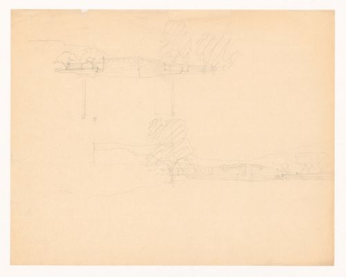
- The perspective sketches correspond with the rough plan, which shows the two wings of the court house and part of the stone wall enclosing the courtyard. The perspective drawing on the lower half of the sheet appears to have been drawn after the plan, which may reflect the architect's approach to the problem: drawing the plan and then working out the relationship between the structure to the site.
DR1994:0006:006
Description:
- The perspective sketches correspond with the rough plan, which shows the two wings of the court house and part of the stone wall enclosing the courtyard. The perspective drawing on the lower half of the sheet appears to have been drawn after the plan, which may reflect the architect's approach to the problem: drawing the plan and then working out the relationship between the structure to the site.
People:
Date:
1934
1934
Title:
Sketch perspectives and sketch plan for Mountain House
Actions:
DR1994:0006:006
Description:
- The perspective sketches correspond with the rough plan, which shows the two wings of the court house and part of the stone wall enclosing the courtyard. The perspective drawing on the lower half of the sheet appears to have been drawn after the plan, which may reflect the architect's approach to the problem: drawing the plan and then working out the relationship between the structure to the site.
Form:
drawings
drawings
Date:
1934
1934
People:
Level of archival description:
Sub-series
Sub-series
Title:
Bloco C, Reconstrução do Chiado [Block C, Reconstruction of the Chiado] Lisbon, Portugal, 1988-1998
Bloco C, Reconstrução do Chiado [Block C, Reconstruction of the Chiado] Lisbon, Portugal, 1988-1998
Actions:
Reference number:
AP178.S1.1988.PR07.SS7
Description:
This project subseries documents Bloco C of the reconstruction of the Chiado in Lisbon, Portugal. The office's archives identified this project as 58/80. The office assigned the dates 1988-1998 for this project. Bloco C was located between Rua Do Crucifixo, Rua Do Carmo, and Rua Nova Do Almada. Bloco C included buildings 1, 2, 3, 4 (Grandes Armazéns do Chiado), 5 (Grandella building), and 6. The construction work for the buildings of Bloco A included the restoration of windows, doors, façades, painting, stonework, as well as work on the structure and mechanical systems. Drawings include studies and working drawings. Textual material includes project documentation and studies. Photographic materials and slides document the buildings prior to the fire, damaged buildings, project site, and construction work. It is important to note that this subseries includes general details of Bloco C, for more specific details see individual building subseries of the Grandella building (AP178.S1.1988.PR07.SS8) and Grandes Armazéns do Chiado (AP178.S1.1988.PR07.SS9).
People:
Date:
1942-2003
1942-2003
Title:
Bloco C, Reconstrução do Chiado [Block C, Reconstruction of the Chiado] Lisbon, Portugal, 1988-1998
Actions:
AP178.S1.1988.PR07.SS7
Description:
This project subseries documents Bloco C of the reconstruction of the Chiado in Lisbon, Portugal. The office's archives identified this project as 58/80. The office assigned the dates 1988-1998 for this project. Bloco C was located between Rua Do Crucifixo, Rua Do Carmo, and Rua Nova Do Almada. Bloco C included buildings 1, 2, 3, 4 (Grandes Armazéns do Chiado), 5 (Grandella building), and 6. The construction work for the buildings of Bloco A included the restoration of windows, doors, façades, painting, stonework, as well as work on the structure and mechanical systems. Drawings include studies and working drawings. Textual material includes project documentation and studies. Photographic materials and slides document the buildings prior to the fire, damaged buildings, project site, and construction work. It is important to note that this subseries includes general details of Bloco C, for more specific details see individual building subseries of the Grandella building (AP178.S1.1988.PR07.SS8) and Grandes Armazéns do Chiado (AP178.S1.1988.PR07.SS9).
Level of archival description:
Project
Project
Date:
1942-2003
1942-2003
People:
Level of archival description:
Project
Project
Reference number:
AP207.S1.2017.PR02
Description:
The project series documents "Architecture Forgiven by Nature", an installation design by Pettena in 2017. The installation consists of an old water tower at the top of a hill in Brufa, covered with a metal grill. The intention is for plants to grow from the grill and hide the tower behind vegetation. The installation also included a staircase hidden behind the metal grill to give access to the top of the tower, so it could be used as a belvedere. "An additional function therefore joins the usual one, as nature helps to integrate a banal architecture into the landscape while also changing it into a place of consciousness and better understanding of both the environment and the art world." [1] The project is also known as "Torre di Brufa". The project series contains a drawing, printouts of digital renderings, plans of the structure surrounding the water tower, and video of Pettena showing the model of the tower. Source: [1] Gianni Pettena website, https://www.giannipettena.it/italiano/opere-1/nat-tower-in-brufa-2017/ (last accessed 28 January 2020)
People:
Date:
2006-2017
2006-2017
Title:
Architecture Forgiven by Nature (2017)
Actions:
AP207.S1.2017.PR02
Description:
The project series documents "Architecture Forgiven by Nature", an installation design by Pettena in 2017. The installation consists of an old water tower at the top of a hill in Brufa, covered with a metal grill. The intention is for plants to grow from the grill and hide the tower behind vegetation. The installation also included a staircase hidden behind the metal grill to give access to the top of the tower, so it could be used as a belvedere. "An additional function therefore joins the usual one, as nature helps to integrate a banal architecture into the landscape while also changing it into a place of consciousness and better understanding of both the environment and the art world." [1] The project is also known as "Torre di Brufa". The project series contains a drawing, printouts of digital renderings, plans of the structure surrounding the water tower, and video of Pettena showing the model of the tower. Source: [1] Gianni Pettena website, https://www.giannipettena.it/italiano/opere-1/nat-tower-in-brufa-2017/ (last accessed 28 January 2020)
Level of archival description:
Project
Project
Date:
2006-2017
2006-2017
People: