4522 Results
Level of archival description:
Project
Project
Actions:
Reference number:
AP056.S1.1987.PR02
Description:
This project series documents a competition entry for the design of Ottawa City Hall in Ottawa, Ontario from 1987-1988. The office identified the project number as 8711. This competition for Ottawa's new city hall called for a contemporary building that would integrate the old city hall, originally built in the 1950s and located on Green Island in the Rideau Canal. Set between Sussex Drive and Union Street, this project consisted of 1 building with 6 distinct parts: the old office building, the new office building, the City Room, the Council Chamber, the podium, and the daycare centre. The old office building was the original modernist-style city hall that would now serve as office spaces for civic workers. It would be renovated to create better circulation with the new extension. The new office building, serving a similar function, would sit behind the old one to create an L-shape on half of the perimeter. It had a large civic tower on one end that would serve as an observation deck. The City Room, a three-storey element in the centre of the structure, had a distinctive roof made up of more than a dozen small pyramids. Whitton Hall would be used as a ceremonial space, the building's lobby, a major central assembly hall, and meeting rooms. The council chambers were located in a self-contained rotunda, which also had press offices on the ground floor. The daycare centre consisted of a rectangular pavilion, set on a diagonal axis from the rest of City Hall. All of these elements sat on a raised podium that had landscaped terraces and gardens around the building's exterior. The terrace offered stunning views of the Ottawa cityscape across the canal. The podium contained one level of parking, with two additional levels below ground. This project was conceptualized to have two distinct fronts, one with its formal address on Sussex Drive that had a ceremonial entrance called the Plaza of Nations, and one off Union Street beneath the podium and underneath the Peace Bell. KPMB's entry proposed a building that would integrate with the existing system of green parks and walkways already present on the island. However, this was not the winning design for the competition and the project was eventually realized by architect Moshe Safdie. This project is recorded through drawings, photographs, a model and watercolour paintings dating from 1987-1988. The drawings are mostly originals and include sketches, surveys and site plans, floor plans, elevations, sections, perspectives and axonometrics of the design. There are also a number of presentation panels that show the final competition submission with short texts about the design intention and construction phasing. The watercolours present the building's exterior and photographs show different views of the project model.
People:
Date:
1987-1988
1987-1988
Title:
Ottawa City Hall Competition, Ontario (1987-1988)
Actions:
AP056.S1.1987.PR02
Description:
This project series documents a competition entry for the design of Ottawa City Hall in Ottawa, Ontario from 1987-1988. The office identified the project number as 8711. This competition for Ottawa's new city hall called for a contemporary building that would integrate the old city hall, originally built in the 1950s and located on Green Island in the Rideau Canal. Set between Sussex Drive and Union Street, this project consisted of 1 building with 6 distinct parts: the old office building, the new office building, the City Room, the Council Chamber, the podium, and the daycare centre. The old office building was the original modernist-style city hall that would now serve as office spaces for civic workers. It would be renovated to create better circulation with the new extension. The new office building, serving a similar function, would sit behind the old one to create an L-shape on half of the perimeter. It had a large civic tower on one end that would serve as an observation deck. The City Room, a three-storey element in the centre of the structure, had a distinctive roof made up of more than a dozen small pyramids. Whitton Hall would be used as a ceremonial space, the building's lobby, a major central assembly hall, and meeting rooms. The council chambers were located in a self-contained rotunda, which also had press offices on the ground floor. The daycare centre consisted of a rectangular pavilion, set on a diagonal axis from the rest of City Hall. All of these elements sat on a raised podium that had landscaped terraces and gardens around the building's exterior. The terrace offered stunning views of the Ottawa cityscape across the canal. The podium contained one level of parking, with two additional levels below ground. This project was conceptualized to have two distinct fronts, one with its formal address on Sussex Drive that had a ceremonial entrance called the Plaza of Nations, and one off Union Street beneath the podium and underneath the Peace Bell. KPMB's entry proposed a building that would integrate with the existing system of green parks and walkways already present on the island. However, this was not the winning design for the competition and the project was eventually realized by architect Moshe Safdie. This project is recorded through drawings, photographs, a model and watercolour paintings dating from 1987-1988. The drawings are mostly originals and include sketches, surveys and site plans, floor plans, elevations, sections, perspectives and axonometrics of the design. There are also a number of presentation panels that show the final competition submission with short texts about the design intention and construction phasing. The watercolours present the building's exterior and photographs show different views of the project model.
Level of archival description:
Project
Project
Date:
1987-1988
1987-1988
People:
Level of archival description:
Sub-series
Sub-series
Actions:
Reference number:
AP018.S1.1980.PR09.SS1
Description:
This project series documents the design and construction of an office building for Marathon Realty in Toronto at the corner of York and Front Streets from 1980-1983. The office identified the project number as 8009. The project consisted of two nineteen storey towers with stainless steel and glass exteriors connected by a glass atrium on each floor. Owned and commissioned by Marathon Realty, the majority of the building’s space was designed for rental. Due to this, the design was highly modular with no interior walls on most floors. Each floor was approximately 18,000 square feet. The ground floor consisted of a lobby, a bank and a restaurant. At the beginning of this project, the project was named Marathon Realty Office Building, Front and York Streets. Soon after, the office building became known as University Place, which it is often referred to as in these materials. Eventually, the building would become the headquarters of CitiBank and renamed Citigroup Place. The project is recorded through drawings, photographs, textual records and other materials dating from 1980-1987. The majority of the drawings are located within the textual records and show the design of building details. Other drawings include site surveys, design development drawings, presentation drawings, and construction drawings. The photographs show construction progress, tests, models, and the finished project. The textual records contain the project proposal, contracts, client and contractor correspondence, inter-office memos, meeting minutes, financial records, change orders, supplementary instructions, specifications, detail planning, artist’s portfolios for the building’s art competition, site inspection reports, and schedules. File AP018.S1.1980.PR09.004 contains an index to the textual records, which was created by the office. The CCA also holds materials for a subproject under this project series, which document the installation of signs to the top of the building after the building's construction (AP018.S1.1980.PR09.SS1). Subproject materials are viewed separately from the project due to the different project numbers originally assigned by the office.
People:
Date:
1980-1987
1980-1987
Title:
University Place Building, Front and York Streets, Toronto (1980-1987)
Actions:
AP018.S1.1980.PR09.SS1
Description:
This project series documents the design and construction of an office building for Marathon Realty in Toronto at the corner of York and Front Streets from 1980-1983. The office identified the project number as 8009. The project consisted of two nineteen storey towers with stainless steel and glass exteriors connected by a glass atrium on each floor. Owned and commissioned by Marathon Realty, the majority of the building’s space was designed for rental. Due to this, the design was highly modular with no interior walls on most floors. Each floor was approximately 18,000 square feet. The ground floor consisted of a lobby, a bank and a restaurant. At the beginning of this project, the project was named Marathon Realty Office Building, Front and York Streets. Soon after, the office building became known as University Place, which it is often referred to as in these materials. Eventually, the building would become the headquarters of CitiBank and renamed Citigroup Place. The project is recorded through drawings, photographs, textual records and other materials dating from 1980-1987. The majority of the drawings are located within the textual records and show the design of building details. Other drawings include site surveys, design development drawings, presentation drawings, and construction drawings. The photographs show construction progress, tests, models, and the finished project. The textual records contain the project proposal, contracts, client and contractor correspondence, inter-office memos, meeting minutes, financial records, change orders, supplementary instructions, specifications, detail planning, artist’s portfolios for the building’s art competition, site inspection reports, and schedules. File AP018.S1.1980.PR09.004 contains an index to the textual records, which was created by the office. The CCA also holds materials for a subproject under this project series, which document the installation of signs to the top of the building after the building's construction (AP018.S1.1980.PR09.SS1). Subproject materials are viewed separately from the project due to the different project numbers originally assigned by the office.
Level of archival description:
Project
Project
Date:
1980-1987
1980-1987
People:
Form:
drawings
Quantity:
20 presentation drawing(s)
drawings
Quantity:
20 presentation drawing(s)
Actions:
Reference number:
DR1995:0188:322-341
Description:
plan of suspension grid, maps of Mill Meads, some showing national transportation, key plans, sections and axonometric drawings of escalators, axonometric drawings and plans showing auditoria, axonometric site plan sketch, lists of activity equipment, diagrams of plans and sections with annotations, structural details, plans, elevations and axonometric drawings of bracing and stair units in service towers
People:
Title:
Plan of suspension grid, maps of Mill Meads, some showing national transportation
Actions:
DR1995:0188:322-341
Description:
plan of suspension grid, maps of Mill Meads, some showing national transportation, key plans, sections and axonometric drawings of escalators, axonometric drawings and plans showing auditoria, axonometric site plan sketch, lists of activity equipment, diagrams of plans and sections with annotations, structural details, plans, elevations and axonometric drawings of bracing and stair units in service towers
Form:
drawings
Quantity:
20 presentation drawing(s)
drawings
Quantity:
20 presentation drawing(s)
People:
Form:
works of art
works of art
Actions:
Reference number:
DR1987:0027
Description:
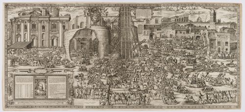
- During the moving of the obelisk, Fontana issued two prints, DR1987:0026 and DR1987:0027. The first (DR1987:0026), was published in March 1586 just prior to the lowering, and distributed with a companion tract by Filippo Pigafetta. It shows both the original and final positions of the obelisk as well as the device proposed by Fontana for its transportation. This involved the use of a twin timber tower (the castello, as it was called, is seen in the central portion of the print) that was erected on either side of the obelisk and was used for lowering and raising the monolith. The second (this print) appeared in August, during the raising, and showed the lowering of the obelisk, as it had occured in late April, with a detailed inventory of all the men and horses involved in the operation. The transportation was begun on 30 April and was completed on 10 September, according to Fontana's description of the process in his book, 'Della trasportione dell'obelisco vaticano' of 1590, a work illustrated by Bonifazio and Guerra, the two artists responsible for the execution of these prints.
DR1987:0027
Description:
- During the moving of the obelisk, Fontana issued two prints, DR1987:0026 and DR1987:0027. The first (DR1987:0026), was published in March 1586 just prior to the lowering, and distributed with a companion tract by Filippo Pigafetta. It shows both the original and final positions of the obelisk as well as the device proposed by Fontana for its transportation. This involved the use of a twin timber tower (the castello, as it was called, is seen in the central portion of the print) that was erected on either side of the obelisk and was used for lowering and raising the monolith. The second (this print) appeared in August, during the raising, and showed the lowering of the obelisk, as it had occured in late April, with a detailed inventory of all the men and horses involved in the operation. The transportation was begun on 30 April and was completed on 10 September, according to Fontana's description of the process in his book, 'Della trasportione dell'obelisco vaticano' of 1590, a work illustrated by Bonifazio and Guerra, the two artists responsible for the execution of these prints.
People:
Subject:
architecture, engineering
architecture, engineering
Date:
published August 1586
published August 1586
Title:
The lowering of the Vatican obelisk
Actions:
DR1987:0027
Description:
- During the moving of the obelisk, Fontana issued two prints, DR1987:0026 and DR1987:0027. The first (DR1987:0026), was published in March 1586 just prior to the lowering, and distributed with a companion tract by Filippo Pigafetta. It shows both the original and final positions of the obelisk as well as the device proposed by Fontana for its transportation. This involved the use of a twin timber tower (the castello, as it was called, is seen in the central portion of the print) that was erected on either side of the obelisk and was used for lowering and raising the monolith. The second (this print) appeared in August, during the raising, and showed the lowering of the obelisk, as it had occured in late April, with a detailed inventory of all the men and horses involved in the operation. The transportation was begun on 30 April and was completed on 10 September, according to Fontana's description of the process in his book, 'Della trasportione dell'obelisco vaticano' of 1590, a work illustrated by Bonifazio and Guerra, the two artists responsible for the execution of these prints.
Form:
works of art
works of art
Date:
published August 1586
published August 1586
People:
Subject:
architecture, engineering
architecture, engineering
Form:
photographs
photographs
Reference number:
ARCH275022
Description:
Presentation slides binder with photographic documentation of various built and un-built projects including: Victoria Hotel (1978); Spadina Quay (1981); Nelson Towers (1968);1300 West Pender Street (1988); Canadian Pacific Hotel (1972); Admiralty Place (1981); Marriot Hotel (1986). Binder also includes some projects from the Vancouver and Los Angeles offices, Arthur Erickson Architects.
People:
Date:
ca. 1979-1988
ca. 1979-1988
Title:
Presentation slides for various projects
Actions:
ARCH275022
Description:
Presentation slides binder with photographic documentation of various built and un-built projects including: Victoria Hotel (1978); Spadina Quay (1981); Nelson Towers (1968);1300 West Pender Street (1988); Canadian Pacific Hotel (1972); Admiralty Place (1981); Marriot Hotel (1986). Binder also includes some projects from the Vancouver and Los Angeles offices, Arthur Erickson Architects.
Form:
photographs
photographs
Date:
ca. 1979-1988
ca. 1979-1988
People:
Form:
drawings
drawings
Reference number:
DR1981:0025
Description:
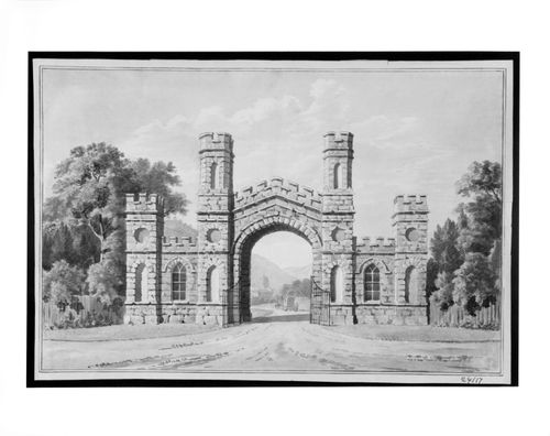
- A full colour rendering of a crenellated Gothick gateway set in a rural landscape. The gateway is comprised of two pairs of short towers, one pair to either side of a central arched passageway, made of stone. Through the central passageway can be seen a horsedrawn coach approaching a very large country house, or palace, which has a tall drum and cupola and a columned portico.
DR1981:0025
Description:
- A full colour rendering of a crenellated Gothick gateway set in a rural landscape. The gateway is comprised of two pairs of short towers, one pair to either side of a central arched passageway, made of stone. Through the central passageway can be seen a horsedrawn coach approaching a very large country house, or palace, which has a tall drum and cupola and a columned portico.
People:
Subject:
architecture, landscape architecture, topographic
architecture, landscape architecture, topographic
Date:
second half of the 18th century
second half of the 18th century
Title:
A Gothick gateway, possibly for Windsor Great Park, Surrey
Actions:
DR1981:0025
Description:
- A full colour rendering of a crenellated Gothick gateway set in a rural landscape. The gateway is comprised of two pairs of short towers, one pair to either side of a central arched passageway, made of stone. Through the central passageway can be seen a horsedrawn coach approaching a very large country house, or palace, which has a tall drum and cupola and a columned portico.
Form:
drawings
drawings
Date:
second half of the 18th century
second half of the 18th century
People:
Subject:
architecture, landscape architecture, topographic
architecture, landscape architecture, topographic
Form:
photographs
photographs
Title:
Views of two models
Views of two models
Reference number:
AP140.S2.SS1.D29.P6
Description:
views of two models, one being a site model in wood (not otherwise present in project documents) that shows an earlier design for the service and circulation towers of the office building, the other being a more detailed model for what is probably the final design that shows the office building in section with the external steel structure and splayed glass wall of the front elevation
People:
Title:
Views of two models
Actions:
AP140.S2.SS1.D29.P6
Description:
views of two models, one being a site model in wood (not otherwise present in project documents) that shows an earlier design for the service and circulation towers of the office building, the other being a more detailed model for what is probably the final design that shows the office building in section with the external steel structure and splayed glass wall of the front elevation
Form:
photographs
photographs
People:
Form:
photographs
photographs
Title:
Views of two models
Views of two models
Actions:
Reference number:
AP140.S2.SS1.D29.P7
Description:
views of two models, one being a site model in wood (not otherwise present in project documents) that shows an earlier design for the service and circulation towers of the office building, the other being a more detailed model for what is probably the final design that shows the office building in section with the external steel structure and splayed glass wall of the front elevation
People:
Date:
1965
1965
Title:
Views of two models
Actions:
AP140.S2.SS1.D29.P7
Description:
views of two models, one being a site model in wood (not otherwise present in project documents) that shows an earlier design for the service and circulation towers of the office building, the other being a more detailed model for what is probably the final design that shows the office building in section with the external steel structure and splayed glass wall of the front elevation
Form:
photographs
photographs
Date:
1965
1965
People:
Form:
photographs
photographs
Title:
Views of two models
Views of two models
Reference number:
AP140.S2.SS1.D29.P8
Description:
views of two models, one being a site model in wood (not otherwise present in project documents) that shows an earlier design for the service and circulation towers of the office building, the other being a more detailed model for what is probably the final design that shows the office building in section with the external steel structure and splayed glass wall of the front elevation
People:
Title:
Views of two models
Actions:
AP140.S2.SS1.D29.P8
Description:
views of two models, one being a site model in wood (not otherwise present in project documents) that shows an earlier design for the service and circulation towers of the office building, the other being a more detailed model for what is probably the final design that shows the office building in section with the external steel structure and splayed glass wall of the front elevation
Form:
photographs
photographs
People:
Form:
photographs
photographs
Title:
Views of two models
Views of two models
Actions:
Reference number:
AP140.S2.SS1.D29.P11
Description:
views of two models, one being a site model in wood (not otherwise present in project documents) that shows an earlier design for the service and circulation towers of the office building, the other being a more detailed model for what is probably the final design that shows the office building in section with the external steel structure and splayed glass wall of the front elevation
People:
Title:
Views of two models
Actions:
AP140.S2.SS1.D29.P11
Description:
views of two models, one being a site model in wood (not otherwise present in project documents) that shows an earlier design for the service and circulation towers of the office building, the other being a more detailed model for what is probably the final design that shows the office building in section with the external steel structure and splayed glass wall of the front elevation
Form:
photographs
photographs
People: