


8579 Results
Form:
textual records
textual records
Actions:
Reference number:
DR1994:0011:026
Description:
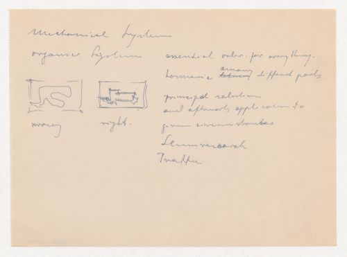
- Group DR1994:0011:001 R/V - DR1994:0011:030 includes three sketches (DR1994:0011:001 R/V - DR1994:0011:002 R/V and DR1994:0011:030), 24 pages of notes (DR1994:0011:003 - DR1994:0011:026), two sketchbooks (DR1994:0011:027:001-035 and DR1994:0011:028:001-008 R/V), and the envelope in which these materials were housed at acquisition (DR1994:0011:029). The sketches are for various subjects including I-beams (DR1994:0011:001 R/V), a column-to-beam connection and an unidentified building (DR1994:0011:002 R/V), and a sketch plan of Mies' 1928-1929 design for the Friedrichstrasse office building in Berlin (DR1994:0011:030). Notes DR1994:0011:003 - DR1994:0011:024 are written in German and are generally illegible. Many changes have been made to the notes, and some sheets appear to have been reordered or struck out. Some of the notes may be about urban planning. The number in the upper left corner of sheets DR1994:0011:010, DR1994:0011:012-016 and DR1994:0011:020-021 may indicate the order of the topics dealt with in the notes. Notes DR1994:0011:025 are illegible. Notes DR1994:0011:026 are written in English, and may be notes of a lecture. The notes in sketchbook DR1994:0011:027:001-035 are written in German, are generally illegible, and are usually written in point form or sometimes as lists. Chicago is mentioned on several of the sheets. There is a shift in the clarity of the handwriting halfway through the sketchbook and some of the notes in the latter half may relate to Mies' readings of philosophy. Some of the notes in sketchbook DR1994:0028:001-008 R/V are written in German and some in English. The first and second pages of the sketchbook describe measurements for addresses on the campus of IIT, as well as for the Power Plant. The last three pages of the sketchbook discuss the architectural education programm at IIT and an exhibition of student work.
DR1994:0011:026
Description:
- Group DR1994:0011:001 R/V - DR1994:0011:030 includes three sketches (DR1994:0011:001 R/V - DR1994:0011:002 R/V and DR1994:0011:030), 24 pages of notes (DR1994:0011:003 - DR1994:0011:026), two sketchbooks (DR1994:0011:027:001-035 and DR1994:0011:028:001-008 R/V), and the envelope in which these materials were housed at acquisition (DR1994:0011:029). The sketches are for various subjects including I-beams (DR1994:0011:001 R/V), a column-to-beam connection and an unidentified building (DR1994:0011:002 R/V), and a sketch plan of Mies' 1928-1929 design for the Friedrichstrasse office building in Berlin (DR1994:0011:030). Notes DR1994:0011:003 - DR1994:0011:024 are written in German and are generally illegible. Many changes have been made to the notes, and some sheets appear to have been reordered or struck out. Some of the notes may be about urban planning. The number in the upper left corner of sheets DR1994:0011:010, DR1994:0011:012-016 and DR1994:0011:020-021 may indicate the order of the topics dealt with in the notes. Notes DR1994:0011:025 are illegible. Notes DR1994:0011:026 are written in English, and may be notes of a lecture. The notes in sketchbook DR1994:0011:027:001-035 are written in German, are generally illegible, and are usually written in point form or sometimes as lists. Chicago is mentioned on several of the sheets. There is a shift in the clarity of the handwriting halfway through the sketchbook and some of the notes in the latter half may relate to Mies' readings of philosophy. Some of the notes in sketchbook DR1994:0028:001-008 R/V are written in German and some in English. The first and second pages of the sketchbook describe measurements for addresses on the campus of IIT, as well as for the Power Plant. The last three pages of the sketchbook discuss the architectural education programm at IIT and an exhibition of student work.
People:
Subject:
architecture
architecture
Date:
1955
1955
Title:
Notes and unidentified sketches
Actions:
DR1994:0011:026
Description:
- Group DR1994:0011:001 R/V - DR1994:0011:030 includes three sketches (DR1994:0011:001 R/V - DR1994:0011:002 R/V and DR1994:0011:030), 24 pages of notes (DR1994:0011:003 - DR1994:0011:026), two sketchbooks (DR1994:0011:027:001-035 and DR1994:0011:028:001-008 R/V), and the envelope in which these materials were housed at acquisition (DR1994:0011:029). The sketches are for various subjects including I-beams (DR1994:0011:001 R/V), a column-to-beam connection and an unidentified building (DR1994:0011:002 R/V), and a sketch plan of Mies' 1928-1929 design for the Friedrichstrasse office building in Berlin (DR1994:0011:030). Notes DR1994:0011:003 - DR1994:0011:024 are written in German and are generally illegible. Many changes have been made to the notes, and some sheets appear to have been reordered or struck out. Some of the notes may be about urban planning. The number in the upper left corner of sheets DR1994:0011:010, DR1994:0011:012-016 and DR1994:0011:020-021 may indicate the order of the topics dealt with in the notes. Notes DR1994:0011:025 are illegible. Notes DR1994:0011:026 are written in English, and may be notes of a lecture. The notes in sketchbook DR1994:0011:027:001-035 are written in German, are generally illegible, and are usually written in point form or sometimes as lists. Chicago is mentioned on several of the sheets. There is a shift in the clarity of the handwriting halfway through the sketchbook and some of the notes in the latter half may relate to Mies' readings of philosophy. Some of the notes in sketchbook DR1994:0028:001-008 R/V are written in German and some in English. The first and second pages of the sketchbook describe measurements for addresses on the campus of IIT, as well as for the Power Plant. The last three pages of the sketchbook discuss the architectural education programm at IIT and an exhibition of student work.
Notes and unidentified sketches
Actions:
DR1994:0011:026
Description:
- Group DR1994:0011:001 R/V - DR1994:0011:030 includes three sketches (DR1994:0011:001 R/V - DR1994:0011:002 R/V and DR1994:0011:030), 24 pages of notes (DR1994:0011:003 - DR1994:0011:026), two sketchbooks (DR1994:0011:027:001-035 and DR1994:0011:028:001-008 R/V), and the envelope in which these materials were housed at acquisition (DR1994:0011:029). The sketches are for various subjects including I-beams (DR1994:0011:001 R/V), a column-to-beam connection and an unidentified building (DR1994:0011:002 R/V), and a sketch plan of Mies' 1928-1929 design for the Friedrichstrasse office building in Berlin (DR1994:0011:030). Notes DR1994:0011:003 - DR1994:0011:024 are written in German and are generally illegible. Many changes have been made to the notes, and some sheets appear to have been reordered or struck out. Some of the notes may be about urban planning. The number in the upper left corner of sheets DR1994:0011:010, DR1994:0011:012-016 and DR1994:0011:020-021 may indicate the order of the topics dealt with in the notes. Notes DR1994:0011:025 are illegible. Notes DR1994:0011:026 are written in English, and may be notes of a lecture. The notes in sketchbook DR1994:0011:027:001-035 are written in German, are generally illegible, and are usually written in point form or sometimes as lists. Chicago is mentioned on several of the sheets. There is a shift in the clarity of the handwriting halfway through the sketchbook and some of the notes in the latter half may relate to Mies' readings of philosophy. Some of the notes in sketchbook DR1994:0028:001-008 R/V are written in German and some in English. The first and second pages of the sketchbook describe measurements for addresses on the campus of IIT, as well as for the Power Plant. The last three pages of the sketchbook discuss the architectural education programm at IIT and an exhibition of student work.
Form:
textual records
textual records
Date:
1955
1955
People:
Subject:
architecture
architecture
Form:
drawings
drawings
Actions:
Reference number:
DR1994:0011:030
Description:
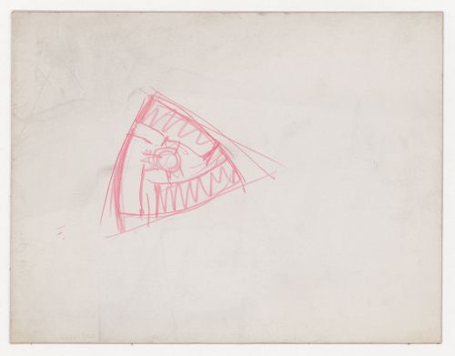
- Group DR1994:0011:001 R/V - DR1994:0011:030 includes three sketches (DR1994:0011:001 R/V - DR1994:0011:002 R/V and DR1994:0011:030), 24 pages of notes (DR1994:0011:003 - DR1994:0011:026), two sketchbooks (DR1994:0011:027:001-035 and DR1994:0011:028:001-008 R/V), and the envelope in which these materials were housed at acquisition (DR1994:0011:029). The sketches are for various subjects including I-beams (DR1994:0011:001 R/V), a column-to-beam connection and an unidentified building (DR1994:0011:002 R/V), and a sketch plan of Mies' 1928-1929 design for the Friedrichstrasse office building in Berlin (DR1994:0011:030). Notes DR1994:0011:003 - DR1994:0011:024 are written in German and are generally illegible. Many changes have been made to the notes, and some sheets appear to have been reordered or struck out. Some of the notes may be about urban planning. The number in the upper left corner of sheets DR1994:0011:010, DR1994:0011:012-016 and DR1994:0011:020-021 may indicate the order of the topics dealt with in the notes. Notes DR1994:0011:025 are illegible. Notes DR1994:0011:026 are written in English, and may be notes of a lecture. The notes in sketchbook DR1994:0011:027:001-035 are written in German, are generally illegible, and are usually written in point form or sometimes as lists. Chicago is mentioned on several of the sheets. There is a shift in the clarity of the handwriting halfway through the sketchbook and some of the notes in the latter half may relate to Mies' readings of philosophy. Some of the notes in sketchbook DR1994:0028:001-008 R/V are written in German and some in English. The first and second pages of the sketchbook describe measurements for addresses on the campus of IIT, as well as for the Power Plant. The last three pages of the sketchbook discuss the architectural education programm at IIT and an exhibition of student work.
DR1994:0011:030
Description:
- Group DR1994:0011:001 R/V - DR1994:0011:030 includes three sketches (DR1994:0011:001 R/V - DR1994:0011:002 R/V and DR1994:0011:030), 24 pages of notes (DR1994:0011:003 - DR1994:0011:026), two sketchbooks (DR1994:0011:027:001-035 and DR1994:0011:028:001-008 R/V), and the envelope in which these materials were housed at acquisition (DR1994:0011:029). The sketches are for various subjects including I-beams (DR1994:0011:001 R/V), a column-to-beam connection and an unidentified building (DR1994:0011:002 R/V), and a sketch plan of Mies' 1928-1929 design for the Friedrichstrasse office building in Berlin (DR1994:0011:030). Notes DR1994:0011:003 - DR1994:0011:024 are written in German and are generally illegible. Many changes have been made to the notes, and some sheets appear to have been reordered or struck out. Some of the notes may be about urban planning. The number in the upper left corner of sheets DR1994:0011:010, DR1994:0011:012-016 and DR1994:0011:020-021 may indicate the order of the topics dealt with in the notes. Notes DR1994:0011:025 are illegible. Notes DR1994:0011:026 are written in English, and may be notes of a lecture. The notes in sketchbook DR1994:0011:027:001-035 are written in German, are generally illegible, and are usually written in point form or sometimes as lists. Chicago is mentioned on several of the sheets. There is a shift in the clarity of the handwriting halfway through the sketchbook and some of the notes in the latter half may relate to Mies' readings of philosophy. Some of the notes in sketchbook DR1994:0028:001-008 R/V are written in German and some in English. The first and second pages of the sketchbook describe measurements for addresses on the campus of IIT, as well as for the Power Plant. The last three pages of the sketchbook discuss the architectural education programm at IIT and an exhibition of student work.
People:
Date:
1955
1955
Title:
Sketch plan of the 1928-1929 design for an office building on the Friedrichstrasse, Berlin
Actions:
DR1994:0011:030
Description:
- Group DR1994:0011:001 R/V - DR1994:0011:030 includes three sketches (DR1994:0011:001 R/V - DR1994:0011:002 R/V and DR1994:0011:030), 24 pages of notes (DR1994:0011:003 - DR1994:0011:026), two sketchbooks (DR1994:0011:027:001-035 and DR1994:0011:028:001-008 R/V), and the envelope in which these materials were housed at acquisition (DR1994:0011:029). The sketches are for various subjects including I-beams (DR1994:0011:001 R/V), a column-to-beam connection and an unidentified building (DR1994:0011:002 R/V), and a sketch plan of Mies' 1928-1929 design for the Friedrichstrasse office building in Berlin (DR1994:0011:030). Notes DR1994:0011:003 - DR1994:0011:024 are written in German and are generally illegible. Many changes have been made to the notes, and some sheets appear to have been reordered or struck out. Some of the notes may be about urban planning. The number in the upper left corner of sheets DR1994:0011:010, DR1994:0011:012-016 and DR1994:0011:020-021 may indicate the order of the topics dealt with in the notes. Notes DR1994:0011:025 are illegible. Notes DR1994:0011:026 are written in English, and may be notes of a lecture. The notes in sketchbook DR1994:0011:027:001-035 are written in German, are generally illegible, and are usually written in point form or sometimes as lists. Chicago is mentioned on several of the sheets. There is a shift in the clarity of the handwriting halfway through the sketchbook and some of the notes in the latter half may relate to Mies' readings of philosophy. Some of the notes in sketchbook DR1994:0028:001-008 R/V are written in German and some in English. The first and second pages of the sketchbook describe measurements for addresses on the campus of IIT, as well as for the Power Plant. The last three pages of the sketchbook discuss the architectural education programm at IIT and an exhibition of student work.
Sketch plan of the 1928-1929 design for an office building on the Friedrichstrasse, Berlin
Actions:
DR1994:0011:030
Description:
- Group DR1994:0011:001 R/V - DR1994:0011:030 includes three sketches (DR1994:0011:001 R/V - DR1994:0011:002 R/V and DR1994:0011:030), 24 pages of notes (DR1994:0011:003 - DR1994:0011:026), two sketchbooks (DR1994:0011:027:001-035 and DR1994:0011:028:001-008 R/V), and the envelope in which these materials were housed at acquisition (DR1994:0011:029). The sketches are for various subjects including I-beams (DR1994:0011:001 R/V), a column-to-beam connection and an unidentified building (DR1994:0011:002 R/V), and a sketch plan of Mies' 1928-1929 design for the Friedrichstrasse office building in Berlin (DR1994:0011:030). Notes DR1994:0011:003 - DR1994:0011:024 are written in German and are generally illegible. Many changes have been made to the notes, and some sheets appear to have been reordered or struck out. Some of the notes may be about urban planning. The number in the upper left corner of sheets DR1994:0011:010, DR1994:0011:012-016 and DR1994:0011:020-021 may indicate the order of the topics dealt with in the notes. Notes DR1994:0011:025 are illegible. Notes DR1994:0011:026 are written in English, and may be notes of a lecture. The notes in sketchbook DR1994:0011:027:001-035 are written in German, are generally illegible, and are usually written in point form or sometimes as lists. Chicago is mentioned on several of the sheets. There is a shift in the clarity of the handwriting halfway through the sketchbook and some of the notes in the latter half may relate to Mies' readings of philosophy. Some of the notes in sketchbook DR1994:0028:001-008 R/V are written in German and some in English. The first and second pages of the sketchbook describe measurements for addresses on the campus of IIT, as well as for the Power Plant. The last three pages of the sketchbook discuss the architectural education programm at IIT and an exhibition of student work.
Form:
drawings
drawings
Date:
1955
1955
People:
Form:
archives
Level of archival description:
Fonds
archives
Level of archival description:
Fonds
Actions:
Reference number:
AP226
Synopsis:
The Toyo Ito & Associates, Architects fonds, 1970 – 2011, documents the studio’s architectural work and involvement in selected exhibitions in the 1970s and 1980s. The records in this fonds represent 34 architectural projects, including built, unbuilt, and conceptual projects. The majority of the projects are located in Japan and are mostly documented through drawings as well as a limited number of videos, models, panels, textual records, and photographs. The fonds also contains records related to Toyo Ito & Associates, Architects’ participation in three exhibitions in the USA and the UK in 1978 and 1986.
AP226
Synopsis:
The Toyo Ito & Associates, Architects fonds, 1970 – 2011, documents the studio’s architectural work and involvement in selected exhibitions in the 1970s and 1980s. The records in this fonds represent 34 architectural projects, including built, unbuilt, and conceptual projects. The majority of the projects are located in Japan and are mostly documented through drawings as well as a limited number of videos, models, panels, textual records, and photographs. The fonds also contains records related to Toyo Ito & Associates, Architects’ participation in three exhibitions in the USA and the UK in 1978 and 1986.
People:
Date:
1970 - 2011
1970 - 2011
Title:
Toyo Ito & Associates, Architects fonds
Actions:
AP226
Synopsis:
The Toyo Ito & Associates, Architects fonds, 1970 – 2011, documents the studio’s architectural work and involvement in selected exhibitions in the 1970s and 1980s. The records in this fonds represent 34 architectural projects, including built, unbuilt, and conceptual projects. The majority of the projects are located in Japan and are mostly documented through drawings as well as a limited number of videos, models, panels, textual records, and photographs. The fonds also contains records related to Toyo Ito & Associates, Architects’ participation in three exhibitions in the USA and the UK in 1978 and 1986.
Toyo Ito & Associates, Architects fonds
Actions:
AP226
Synopsis:
The Toyo Ito & Associates, Architects fonds, 1970 – 2011, documents the studio’s architectural work and involvement in selected exhibitions in the 1970s and 1980s. The records in this fonds represent 34 architectural projects, including built, unbuilt, and conceptual projects. The majority of the projects are located in Japan and are mostly documented through drawings as well as a limited number of videos, models, panels, textual records, and photographs. The fonds also contains records related to Toyo Ito & Associates, Architects’ participation in three exhibitions in the USA and the UK in 1978 and 1986.
Form:
archives
Level of archival description:
Fonds
archives
Level of archival description:
Fonds
Date:
1970 - 2011
1970 - 2011
People:
Form:
archives
Level of archival description:
Fonds
archives
Level of archival description:
Fonds
Reference number:
AP189
Synopsis:
L’installation Météorologie d’intérieur fut présentée au Centre Canadien d’Architecture (CCA) lors de l’exposition Environ(ne)ment (18 octobre 2006-10 juin 2007) et à Rovereto en Italie lors de l’exposition Manifesta 7 (19 juillet-2 novembre 2008). Les documents d’archives de l’installation comprennent le logiciel développé pour l’installation et une sélection des objets installés dans les deux espaces d’exposition. *** The installation Interior Weather was presented at the Candian Centre for Architecture (CCA) as part of the exhibition Environ(ne)ment (October 18, 2006-June 10, 2007) and in Rovereto, Italy as part of Manifesta 7 (July 19-November 2, 2008). The records of the installation Interior Weather include the software developed for the installation and a selection of objects installed in the exhibition spaces.
AP189
Synopsis:
L’installation Météorologie d’intérieur fut présentée au Centre Canadien d’Architecture (CCA) lors de l’exposition Environ(ne)ment (18 octobre 2006-10 juin 2007) et à Rovereto en Italie lors de l’exposition Manifesta 7 (19 juillet-2 novembre 2008). Les documents d’archives de l’installation comprennent le logiciel développé pour l’installation et une sélection des objets installés dans les deux espaces d’exposition. *** The installation Interior Weather was presented at the Candian Centre for Architecture (CCA) as part of the exhibition Environ(ne)ment (October 18, 2006-June 10, 2007) and in Rovereto, Italy as part of Manifesta 7 (July 19-November 2, 2008). The records of the installation Interior Weather include the software developed for the installation and a selection of objects installed in the exhibition spaces.
People:
Date:
2000-2008
2000-2008
Title:
Philippe Rahm "Interior Weather" installation records
Actions:
AP189
Synopsis:
L’installation Météorologie d’intérieur fut présentée au Centre Canadien d’Architecture (CCA) lors de l’exposition Environ(ne)ment (18 octobre 2006-10 juin 2007) et à Rovereto en Italie lors de l’exposition Manifesta 7 (19 juillet-2 novembre 2008). Les documents d’archives de l’installation comprennent le logiciel développé pour l’installation et une sélection des objets installés dans les deux espaces d’exposition. *** The installation Interior Weather was presented at the Candian Centre for Architecture (CCA) as part of the exhibition Environ(ne)ment (October 18, 2006-June 10, 2007) and in Rovereto, Italy as part of Manifesta 7 (July 19-November 2, 2008). The records of the installation Interior Weather include the software developed for the installation and a selection of objects installed in the exhibition spaces.
Philippe Rahm "Interior Weather" installation records
Actions:
AP189
Synopsis:
L’installation Météorologie d’intérieur fut présentée au Centre Canadien d’Architecture (CCA) lors de l’exposition Environ(ne)ment (18 octobre 2006-10 juin 2007) et à Rovereto en Italie lors de l’exposition Manifesta 7 (19 juillet-2 novembre 2008). Les documents d’archives de l’installation comprennent le logiciel développé pour l’installation et une sélection des objets installés dans les deux espaces d’exposition. *** The installation Interior Weather was presented at the Candian Centre for Architecture (CCA) as part of the exhibition Environ(ne)ment (October 18, 2006-June 10, 2007) and in Rovereto, Italy as part of Manifesta 7 (July 19-November 2, 2008). The records of the installation Interior Weather include the software developed for the installation and a selection of objects installed in the exhibition spaces.
Form:
archives
Level of archival description:
Fonds
archives
Level of archival description:
Fonds
Date:
2000-2008
2000-2008
People:
Level of archival description:
Project
Project
Title:
O.C.H. Feasibility Study
O.C.H. Feasibility Study
Reference number:
AP144.S2.D59
Description:
File documents a feasibility study commissioned by J. Lyons Co. Ltd for the conversion of the Oxford Corner House, in London, England, United Kingdom, into a combined information, education and skill centre. The unrealized project was to include a 'self-pace public skill and information hive' with facilities for conferences, teaching, exhibitions, computer use, planetarium, audio-visual library, and public eating areas. The project included a movable floor system and projection screens. Reference material includes plans and details of London Electric Railway subway line, alterations to Oxford Street Corner House by J. Lyons and Co. Ltd., field notes, photographs and photomontages of site. Conceptual diagrammatic plans explore designs for the organization of activities. Charts show variables, including number of people, monitors/screens, and study carrels; circulation patterns; and maximization of viewing capacity. Preliminary presentation boards illustrate project feasibility and include photographs of model and existing conditions. Design development drawings include floor plans, plans exploring the relationships between various activities, analysis of building volumes and networks, comparative plans showing main structural grid, sections, diagrammatic sections for public activity areas, axonometric drawings of roof, perspectives of projection screens and moveable floor system, progress charts, and diagrams and graphs of communication and travel modes, routes, and time into central London from outlying areas. Some material in this file was published in Price, Cedric. 'Cedric Price-Works II' (London: Architectural Press, 1984), 11, 54, 112; Landau, Royston. 'New Directions in British Architecture'. New York: George Braziller, 1968. 108-111; and 'Self-Pace Public Skill and Information Hive.' 'Architectural Design'. (May 1968), 237-239. Material in this file was produced between 1927 and 1967, but predominantly between 1965 and 1966. Group DR1995:0224:001-013 contains reference drawings attributed to London Transport Architect's Department and J. Lyons & Company Limited Architect's Office. Group DR1995:0224:333-341 contains drawings attributed to Richard Sutcliffe Limited, Felix J. Samuely & Partners, and G.E.C. (Process Engineering) Ltd. File contains conceptual drawings, consultant drawings, design development drawings, presentation drawings, presentation panels, reference drawings, photographic material, and textual records.
AP144.S2.D59
Description:
File documents a feasibility study commissioned by J. Lyons Co. Ltd for the conversion of the Oxford Corner House, in London, England, United Kingdom, into a combined information, education and skill centre. The unrealized project was to include a 'self-pace public skill and information hive' with facilities for conferences, teaching, exhibitions, computer use, planetarium, audio-visual library, and public eating areas. The project included a movable floor system and projection screens. Reference material includes plans and details of London Electric Railway subway line, alterations to Oxford Street Corner House by J. Lyons and Co. Ltd., field notes, photographs and photomontages of site. Conceptual diagrammatic plans explore designs for the organization of activities. Charts show variables, including number of people, monitors/screens, and study carrels; circulation patterns; and maximization of viewing capacity. Preliminary presentation boards illustrate project feasibility and include photographs of model and existing conditions. Design development drawings include floor plans, plans exploring the relationships between various activities, analysis of building volumes and networks, comparative plans showing main structural grid, sections, diagrammatic sections for public activity areas, axonometric drawings of roof, perspectives of projection screens and moveable floor system, progress charts, and diagrams and graphs of communication and travel modes, routes, and time into central London from outlying areas. Some material in this file was published in Price, Cedric. 'Cedric Price-Works II' (London: Architectural Press, 1984), 11, 54, 112; Landau, Royston. 'New Directions in British Architecture'. New York: George Braziller, 1968. 108-111; and 'Self-Pace Public Skill and Information Hive.' 'Architectural Design'. (May 1968), 237-239. Material in this file was produced between 1927 and 1967, but predominantly between 1965 and 1966. Group DR1995:0224:001-013 contains reference drawings attributed to London Transport Architect's Department and J. Lyons & Company Limited Architect's Office. Group DR1995:0224:333-341 contains drawings attributed to Richard Sutcliffe Limited, Felix J. Samuely & Partners, and G.E.C. (Process Engineering) Ltd. File contains conceptual drawings, consultant drawings, design development drawings, presentation drawings, presentation panels, reference drawings, photographic material, and textual records.
People:
Date:
1927-1967, predominant 1965-1966
1927-1967, predominant 1965-1966
Title:
O.C.H. Feasibility Study
Actions:
AP144.S2.D59
Description:
File documents a feasibility study commissioned by J. Lyons Co. Ltd for the conversion of the Oxford Corner House, in London, England, United Kingdom, into a combined information, education and skill centre. The unrealized project was to include a 'self-pace public skill and information hive' with facilities for conferences, teaching, exhibitions, computer use, planetarium, audio-visual library, and public eating areas. The project included a movable floor system and projection screens. Reference material includes plans and details of London Electric Railway subway line, alterations to Oxford Street Corner House by J. Lyons and Co. Ltd., field notes, photographs and photomontages of site. Conceptual diagrammatic plans explore designs for the organization of activities. Charts show variables, including number of people, monitors/screens, and study carrels; circulation patterns; and maximization of viewing capacity. Preliminary presentation boards illustrate project feasibility and include photographs of model and existing conditions. Design development drawings include floor plans, plans exploring the relationships between various activities, analysis of building volumes and networks, comparative plans showing main structural grid, sections, diagrammatic sections for public activity areas, axonometric drawings of roof, perspectives of projection screens and moveable floor system, progress charts, and diagrams and graphs of communication and travel modes, routes, and time into central London from outlying areas. Some material in this file was published in Price, Cedric. 'Cedric Price-Works II' (London: Architectural Press, 1984), 11, 54, 112; Landau, Royston. 'New Directions in British Architecture'. New York: George Braziller, 1968. 108-111; and 'Self-Pace Public Skill and Information Hive.' 'Architectural Design'. (May 1968), 237-239. Material in this file was produced between 1927 and 1967, but predominantly between 1965 and 1966. Group DR1995:0224:001-013 contains reference drawings attributed to London Transport Architect's Department and J. Lyons & Company Limited Architect's Office. Group DR1995:0224:333-341 contains drawings attributed to Richard Sutcliffe Limited, Felix J. Samuely & Partners, and G.E.C. (Process Engineering) Ltd. File contains conceptual drawings, consultant drawings, design development drawings, presentation drawings, presentation panels, reference drawings, photographic material, and textual records.
O.C.H. Feasibility Study
Actions:
AP144.S2.D59
Description:
File documents a feasibility study commissioned by J. Lyons Co. Ltd for the conversion of the Oxford Corner House, in London, England, United Kingdom, into a combined information, education and skill centre. The unrealized project was to include a 'self-pace public skill and information hive' with facilities for conferences, teaching, exhibitions, computer use, planetarium, audio-visual library, and public eating areas. The project included a movable floor system and projection screens. Reference material includes plans and details of London Electric Railway subway line, alterations to Oxford Street Corner House by J. Lyons and Co. Ltd., field notes, photographs and photomontages of site. Conceptual diagrammatic plans explore designs for the organization of activities. Charts show variables, including number of people, monitors/screens, and study carrels; circulation patterns; and maximization of viewing capacity. Preliminary presentation boards illustrate project feasibility and include photographs of model and existing conditions. Design development drawings include floor plans, plans exploring the relationships between various activities, analysis of building volumes and networks, comparative plans showing main structural grid, sections, diagrammatic sections for public activity areas, axonometric drawings of roof, perspectives of projection screens and moveable floor system, progress charts, and diagrams and graphs of communication and travel modes, routes, and time into central London from outlying areas. Some material in this file was published in Price, Cedric. 'Cedric Price-Works II' (London: Architectural Press, 1984), 11, 54, 112; Landau, Royston. 'New Directions in British Architecture'. New York: George Braziller, 1968. 108-111; and 'Self-Pace Public Skill and Information Hive.' 'Architectural Design'. (May 1968), 237-239. Material in this file was produced between 1927 and 1967, but predominantly between 1965 and 1966. Group DR1995:0224:001-013 contains reference drawings attributed to London Transport Architect's Department and J. Lyons & Company Limited Architect's Office. Group DR1995:0224:333-341 contains drawings attributed to Richard Sutcliffe Limited, Felix J. Samuely & Partners, and G.E.C. (Process Engineering) Ltd. File contains conceptual drawings, consultant drawings, design development drawings, presentation drawings, presentation panels, reference drawings, photographic material, and textual records.
Level of archival description:
File 59
File 59
Date:
1927-1967, predominant 1965-1966
1927-1967, predominant 1965-1966
People:
Level of archival description:
Project
Project
Actions:
Reference number:
AP018.S1.1974.PR07
Description:
This project series documents long-term planning for airports near Kabul, Afghanistan from 1974-1990. The office identified the project number as 7408. This project consisted of the planning of airports near Kabul for the years 1974-1990. This work was undertaken in joint venture with other Canadian firms who worked together on airport planning projects around the world. The firms, which consisted of Parkin Architects Planners as the architects, the Montreal Engineering Company Limited, and Peat, Marwick and Partners, joined with the local Afghan Bureau of Consulting Architects and Engineers for this project. It was to be funded by the Islamic Bank, with the Canadian government paying the design fees. The proposed airport, referred to as Logar Airport, consisted of a rectangular passenger terminal with each level set back to create the look of a staircase roofline. A 225 car parking lot, an administration building and a tower in the parking lot area were also included. The long-term plan showed a symmetrical addition built onto the passenger building and symmetrical 225 car parking lot to compliment it in the years following the original construction. An airport hotel was also proposed for future additions. A feasibility study for this project investigated Logar as a site for the airport, based on the ability to expand the terminal size for passenger processing and traffic, and the flexibility of the local topography. Planing, deplaning, processing and passenger flows were all investigated in this project, along with phasing and development plans. It is not clear from the project documentation if this project was ever built. The project is recorded through drawings, a photograph, and textual records dating from 1974-1976. The drawings include a large number of base plans with overlays to study planing and deplaning flows, natural lighting, and passenger movements. Plans, sections and presentation drawings are also included. The textual records consist of reports on the project program and costs, interoffice memos, correspondence, and financial records.
AP018.S1.1974.PR07
Description:
This project series documents long-term planning for airports near Kabul, Afghanistan from 1974-1990. The office identified the project number as 7408. This project consisted of the planning of airports near Kabul for the years 1974-1990. This work was undertaken in joint venture with other Canadian firms who worked together on airport planning projects around the world. The firms, which consisted of Parkin Architects Planners as the architects, the Montreal Engineering Company Limited, and Peat, Marwick and Partners, joined with the local Afghan Bureau of Consulting Architects and Engineers for this project. It was to be funded by the Islamic Bank, with the Canadian government paying the design fees. The proposed airport, referred to as Logar Airport, consisted of a rectangular passenger terminal with each level set back to create the look of a staircase roofline. A 225 car parking lot, an administration building and a tower in the parking lot area were also included. The long-term plan showed a symmetrical addition built onto the passenger building and symmetrical 225 car parking lot to compliment it in the years following the original construction. An airport hotel was also proposed for future additions. A feasibility study for this project investigated Logar as a site for the airport, based on the ability to expand the terminal size for passenger processing and traffic, and the flexibility of the local topography. Planing, deplaning, processing and passenger flows were all investigated in this project, along with phasing and development plans. It is not clear from the project documentation if this project was ever built. The project is recorded through drawings, a photograph, and textual records dating from 1974-1976. The drawings include a large number of base plans with overlays to study planing and deplaning flows, natural lighting, and passenger movements. Plans, sections and presentation drawings are also included. The textual records consist of reports on the project program and costs, interoffice memos, correspondence, and financial records.
People:
Date:
1974-1976
1974-1976
Title:
Kabul Area Airport Developments, Afghanistan (1974-1990)
Actions:
AP018.S1.1974.PR07
Description:
This project series documents long-term planning for airports near Kabul, Afghanistan from 1974-1990. The office identified the project number as 7408. This project consisted of the planning of airports near Kabul for the years 1974-1990. This work was undertaken in joint venture with other Canadian firms who worked together on airport planning projects around the world. The firms, which consisted of Parkin Architects Planners as the architects, the Montreal Engineering Company Limited, and Peat, Marwick and Partners, joined with the local Afghan Bureau of Consulting Architects and Engineers for this project. It was to be funded by the Islamic Bank, with the Canadian government paying the design fees. The proposed airport, referred to as Logar Airport, consisted of a rectangular passenger terminal with each level set back to create the look of a staircase roofline. A 225 car parking lot, an administration building and a tower in the parking lot area were also included. The long-term plan showed a symmetrical addition built onto the passenger building and symmetrical 225 car parking lot to compliment it in the years following the original construction. An airport hotel was also proposed for future additions. A feasibility study for this project investigated Logar as a site for the airport, based on the ability to expand the terminal size for passenger processing and traffic, and the flexibility of the local topography. Planing, deplaning, processing and passenger flows were all investigated in this project, along with phasing and development plans. It is not clear from the project documentation if this project was ever built. The project is recorded through drawings, a photograph, and textual records dating from 1974-1976. The drawings include a large number of base plans with overlays to study planing and deplaning flows, natural lighting, and passenger movements. Plans, sections and presentation drawings are also included. The textual records consist of reports on the project program and costs, interoffice memos, correspondence, and financial records.
Kabul Area Airport Developments, Afghanistan (1974-1990)
Actions:
AP018.S1.1974.PR07
Description:
This project series documents long-term planning for airports near Kabul, Afghanistan from 1974-1990. The office identified the project number as 7408. This project consisted of the planning of airports near Kabul for the years 1974-1990. This work was undertaken in joint venture with other Canadian firms who worked together on airport planning projects around the world. The firms, which consisted of Parkin Architects Planners as the architects, the Montreal Engineering Company Limited, and Peat, Marwick and Partners, joined with the local Afghan Bureau of Consulting Architects and Engineers for this project. It was to be funded by the Islamic Bank, with the Canadian government paying the design fees. The proposed airport, referred to as Logar Airport, consisted of a rectangular passenger terminal with each level set back to create the look of a staircase roofline. A 225 car parking lot, an administration building and a tower in the parking lot area were also included. The long-term plan showed a symmetrical addition built onto the passenger building and symmetrical 225 car parking lot to compliment it in the years following the original construction. An airport hotel was also proposed for future additions. A feasibility study for this project investigated Logar as a site for the airport, based on the ability to expand the terminal size for passenger processing and traffic, and the flexibility of the local topography. Planing, deplaning, processing and passenger flows were all investigated in this project, along with phasing and development plans. It is not clear from the project documentation if this project was ever built. The project is recorded through drawings, a photograph, and textual records dating from 1974-1976. The drawings include a large number of base plans with overlays to study planing and deplaning flows, natural lighting, and passenger movements. Plans, sections and presentation drawings are also included. The textual records consist of reports on the project program and costs, interoffice memos, correspondence, and financial records.
Level of archival description:
Project
Project
Date:
1974-1976
1974-1976
People:
Level of archival description:
Project
Project
Actions:
Reference number:
AP018.S1.1976.PR23
Description:
This project series documents the design of the new National Gallery of Canada for a limited architectural competition in Ottawa, Ontario in 1976. The office identified the project number as 7630. This project consisted of designing a new gallery to house Canada's most prized artworks and artefacts in a competition run by Public Works Canada on behalf of National Museums of Canada. The building site was down the street from Canada's parliament buildings, with views of the Ottawa River and across to Quebec. The design submitted by Parkin Architects Planners was highly modular, with cubes turned on an angle making up the majority of the building. The six-storey building design had three floors of galleries, while other levels were to be used for staff, services, and storage. A panel of international architects and representatives anonymously chose Parkin's design as the winner of the competition in early 1977. However, after cited lack of funds, and controversies over the chosen site and the way in which the competition was run, the newly formed Canada Museums Construction Company sought another design and architect for the new National Gallery. The dispute over this decision is recorded in materials from this project series and related project series. Eventually, Parkin did participate in the construction of the National Gallery's final design, but as the minor partner in a joint venture with Moshe Safdie (see materials in project series AP018.S1.1983.PR02 in this fonds for more information). The project is recorded through drawings, including presentation boards, photographs, and textual records dating from 1974-1985. The drawings are a mix of original design drawings and site drawings. The site drawings were prepared for the competitors by Public Works Canada and the National Capital Commission. The drawings prepared by these government agencies are bilingual. The textual records primarily consist of guidelines, specifications, and other information from Public Works Canada to the competitors. The textual documentation also includes financial records and correspondence on the controversy surrounding the competition.
AP018.S1.1976.PR23
Description:
This project series documents the design of the new National Gallery of Canada for a limited architectural competition in Ottawa, Ontario in 1976. The office identified the project number as 7630. This project consisted of designing a new gallery to house Canada's most prized artworks and artefacts in a competition run by Public Works Canada on behalf of National Museums of Canada. The building site was down the street from Canada's parliament buildings, with views of the Ottawa River and across to Quebec. The design submitted by Parkin Architects Planners was highly modular, with cubes turned on an angle making up the majority of the building. The six-storey building design had three floors of galleries, while other levels were to be used for staff, services, and storage. A panel of international architects and representatives anonymously chose Parkin's design as the winner of the competition in early 1977. However, after cited lack of funds, and controversies over the chosen site and the way in which the competition was run, the newly formed Canada Museums Construction Company sought another design and architect for the new National Gallery. The dispute over this decision is recorded in materials from this project series and related project series. Eventually, Parkin did participate in the construction of the National Gallery's final design, but as the minor partner in a joint venture with Moshe Safdie (see materials in project series AP018.S1.1983.PR02 in this fonds for more information). The project is recorded through drawings, including presentation boards, photographs, and textual records dating from 1974-1985. The drawings are a mix of original design drawings and site drawings. The site drawings were prepared for the competitors by Public Works Canada and the National Capital Commission. The drawings prepared by these government agencies are bilingual. The textual records primarily consist of guidelines, specifications, and other information from Public Works Canada to the competitors. The textual documentation also includes financial records and correspondence on the controversy surrounding the competition.
People:
Date:
1974-1985
1974-1985
Title:
National Gallery of Canada, Limited Architectural Competition, Ottawa, Ontario (1976)
Actions:
AP018.S1.1976.PR23
Description:
This project series documents the design of the new National Gallery of Canada for a limited architectural competition in Ottawa, Ontario in 1976. The office identified the project number as 7630. This project consisted of designing a new gallery to house Canada's most prized artworks and artefacts in a competition run by Public Works Canada on behalf of National Museums of Canada. The building site was down the street from Canada's parliament buildings, with views of the Ottawa River and across to Quebec. The design submitted by Parkin Architects Planners was highly modular, with cubes turned on an angle making up the majority of the building. The six-storey building design had three floors of galleries, while other levels were to be used for staff, services, and storage. A panel of international architects and representatives anonymously chose Parkin's design as the winner of the competition in early 1977. However, after cited lack of funds, and controversies over the chosen site and the way in which the competition was run, the newly formed Canada Museums Construction Company sought another design and architect for the new National Gallery. The dispute over this decision is recorded in materials from this project series and related project series. Eventually, Parkin did participate in the construction of the National Gallery's final design, but as the minor partner in a joint venture with Moshe Safdie (see materials in project series AP018.S1.1983.PR02 in this fonds for more information). The project is recorded through drawings, including presentation boards, photographs, and textual records dating from 1974-1985. The drawings are a mix of original design drawings and site drawings. The site drawings were prepared for the competitors by Public Works Canada and the National Capital Commission. The drawings prepared by these government agencies are bilingual. The textual records primarily consist of guidelines, specifications, and other information from Public Works Canada to the competitors. The textual documentation also includes financial records and correspondence on the controversy surrounding the competition.
National Gallery of Canada, Limited Architectural Competition, Ottawa, Ontario (1976)
Actions:
AP018.S1.1976.PR23
Description:
This project series documents the design of the new National Gallery of Canada for a limited architectural competition in Ottawa, Ontario in 1976. The office identified the project number as 7630. This project consisted of designing a new gallery to house Canada's most prized artworks and artefacts in a competition run by Public Works Canada on behalf of National Museums of Canada. The building site was down the street from Canada's parliament buildings, with views of the Ottawa River and across to Quebec. The design submitted by Parkin Architects Planners was highly modular, with cubes turned on an angle making up the majority of the building. The six-storey building design had three floors of galleries, while other levels were to be used for staff, services, and storage. A panel of international architects and representatives anonymously chose Parkin's design as the winner of the competition in early 1977. However, after cited lack of funds, and controversies over the chosen site and the way in which the competition was run, the newly formed Canada Museums Construction Company sought another design and architect for the new National Gallery. The dispute over this decision is recorded in materials from this project series and related project series. Eventually, Parkin did participate in the construction of the National Gallery's final design, but as the minor partner in a joint venture with Moshe Safdie (see materials in project series AP018.S1.1983.PR02 in this fonds for more information). The project is recorded through drawings, including presentation boards, photographs, and textual records dating from 1974-1985. The drawings are a mix of original design drawings and site drawings. The site drawings were prepared for the competitors by Public Works Canada and the National Capital Commission. The drawings prepared by these government agencies are bilingual. The textual records primarily consist of guidelines, specifications, and other information from Public Works Canada to the competitors. The textual documentation also includes financial records and correspondence on the controversy surrounding the competition.
Level of archival description:
Project
Project
Date:
1974-1985
1974-1985
People:
Form:
textual records
textual records
Actions:
Reference number:
DR2001:0030
Description:
documents include lectures, 1989-1992; travel files, 1991-1992; letters of recommendation, 1991-1992. Lecture file schedule: Ching (Chinese community lectures) 11/29 - 11/30, lecture requests rejected.File folder "lectures 1989 - finished": miscellaneous papers concerning planning, contacts, travel, etc. File folder "lectures 1991":Wiesbaden 1991, Seton Hill / Philip Johnson, 09/14/91 lecture, santander (University) Barcelona 8/19 lecture honorarium, Western Mountain Region (AIA) Salt Lake (City) 09/21/91, Mississippi State Lecture Honorarium 09/16/91, Central States Regional AIA Convention, Des Moines, 10/10-11, University of Michigan Lecture Honorarium 11/22/91, San Francisco Museum of Modern Art, Lecture Honoraria, University of Minnesota Lecture Honoraria, College of Architecture, Clemson, S.C. (1990), Museum of Contemporary Art (Chicago, 1990), The Savannah College (of Art and Design, 1990), The University of Michigan, Clemson University, Atlanta ADAC (Decorative Arts Center) July 22-23/91. PDE - Keynote Speaker. Contact Susan Fite, Ando - Century Club, Oct. 1/91. RSVP and Invitations: Georgia Tech. 01/14/92. File Folder - "Travel", 1991-1992:Naples, Germany Trip 12/15-12/18, Atlanta > Frankfurt > Berlin, Frankfurt Trip, Spain 1992, Japan Trip, Frankfurt Trip with Schwan & kreis(berg), Berlin Frank(furt) Trip. PDE, CCD, SCE, 05/20/92 Germany France Trip, Germany 6/29-30, Germany 3/24, memorabilia. File Folder - "letters of recommendation / reference," 1991-1992: Robert Montray Thesis, Georgia Institute of Technology, Raphael Mone, David Niland, Office for Metro. Arch., Sarah Whiting, Recommendation - Milanini, letter of Reference - J. Ben Gianni, letters of Reference, reference letters and Friedrich K.M. Bohm.
DR2001:0030
Description:
documents include lectures, 1989-1992; travel files, 1991-1992; letters of recommendation, 1991-1992. Lecture file schedule: Ching (Chinese community lectures) 11/29 - 11/30, lecture requests rejected.File folder "lectures 1989 - finished": miscellaneous papers concerning planning, contacts, travel, etc. File folder "lectures 1991":Wiesbaden 1991, Seton Hill / Philip Johnson, 09/14/91 lecture, santander (University) Barcelona 8/19 lecture honorarium, Western Mountain Region (AIA) Salt Lake (City) 09/21/91, Mississippi State Lecture Honorarium 09/16/91, Central States Regional AIA Convention, Des Moines, 10/10-11, University of Michigan Lecture Honorarium 11/22/91, San Francisco Museum of Modern Art, Lecture Honoraria, University of Minnesota Lecture Honoraria, College of Architecture, Clemson, S.C. (1990), Museum of Contemporary Art (Chicago, 1990), The Savannah College (of Art and Design, 1990), The University of Michigan, Clemson University, Atlanta ADAC (Decorative Arts Center) July 22-23/91. PDE - Keynote Speaker. Contact Susan Fite, Ando - Century Club, Oct. 1/91. RSVP and Invitations: Georgia Tech. 01/14/92. File Folder - "Travel", 1991-1992:Naples, Germany Trip 12/15-12/18, Atlanta > Frankfurt > Berlin, Frankfurt Trip, Spain 1992, Japan Trip, Frankfurt Trip with Schwan & kreis(berg), Berlin Frank(furt) Trip. PDE, CCD, SCE, 05/20/92 Germany France Trip, Germany 6/29-30, Germany 3/24, memorabilia. File Folder - "letters of recommendation / reference," 1991-1992: Robert Montray Thesis, Georgia Institute of Technology, Raphael Mone, David Niland, Office for Metro. Arch., Sarah Whiting, Recommendation - Milanini, letter of Reference - J. Ben Gianni, letters of Reference, reference letters and Friedrich K.M. Bohm.
People:
Title:
Documents include lectures, 1989-1992
Actions:
DR2001:0030
Description:
documents include lectures, 1989-1992; travel files, 1991-1992; letters of recommendation, 1991-1992. Lecture file schedule: Ching (Chinese community lectures) 11/29 - 11/30, lecture requests rejected.File folder "lectures 1989 - finished": miscellaneous papers concerning planning, contacts, travel, etc. File folder "lectures 1991":Wiesbaden 1991, Seton Hill / Philip Johnson, 09/14/91 lecture, santander (University) Barcelona 8/19 lecture honorarium, Western Mountain Region (AIA) Salt Lake (City) 09/21/91, Mississippi State Lecture Honorarium 09/16/91, Central States Regional AIA Convention, Des Moines, 10/10-11, University of Michigan Lecture Honorarium 11/22/91, San Francisco Museum of Modern Art, Lecture Honoraria, University of Minnesota Lecture Honoraria, College of Architecture, Clemson, S.C. (1990), Museum of Contemporary Art (Chicago, 1990), The Savannah College (of Art and Design, 1990), The University of Michigan, Clemson University, Atlanta ADAC (Decorative Arts Center) July 22-23/91. PDE - Keynote Speaker. Contact Susan Fite, Ando - Century Club, Oct. 1/91. RSVP and Invitations: Georgia Tech. 01/14/92. File Folder - "Travel", 1991-1992:Naples, Germany Trip 12/15-12/18, Atlanta > Frankfurt > Berlin, Frankfurt Trip, Spain 1992, Japan Trip, Frankfurt Trip with Schwan & kreis(berg), Berlin Frank(furt) Trip. PDE, CCD, SCE, 05/20/92 Germany France Trip, Germany 6/29-30, Germany 3/24, memorabilia. File Folder - "letters of recommendation / reference," 1991-1992: Robert Montray Thesis, Georgia Institute of Technology, Raphael Mone, David Niland, Office for Metro. Arch., Sarah Whiting, Recommendation - Milanini, letter of Reference - J. Ben Gianni, letters of Reference, reference letters and Friedrich K.M. Bohm.
Documents include lectures, 1989-1992
Actions:
DR2001:0030
Description:
documents include lectures, 1989-1992; travel files, 1991-1992; letters of recommendation, 1991-1992. Lecture file schedule: Ching (Chinese community lectures) 11/29 - 11/30, lecture requests rejected.File folder "lectures 1989 - finished": miscellaneous papers concerning planning, contacts, travel, etc. File folder "lectures 1991":Wiesbaden 1991, Seton Hill / Philip Johnson, 09/14/91 lecture, santander (University) Barcelona 8/19 lecture honorarium, Western Mountain Region (AIA) Salt Lake (City) 09/21/91, Mississippi State Lecture Honorarium 09/16/91, Central States Regional AIA Convention, Des Moines, 10/10-11, University of Michigan Lecture Honorarium 11/22/91, San Francisco Museum of Modern Art, Lecture Honoraria, University of Minnesota Lecture Honoraria, College of Architecture, Clemson, S.C. (1990), Museum of Contemporary Art (Chicago, 1990), The Savannah College (of Art and Design, 1990), The University of Michigan, Clemson University, Atlanta ADAC (Decorative Arts Center) July 22-23/91. PDE - Keynote Speaker. Contact Susan Fite, Ando - Century Club, Oct. 1/91. RSVP and Invitations: Georgia Tech. 01/14/92. File Folder - "Travel", 1991-1992:Naples, Germany Trip 12/15-12/18, Atlanta > Frankfurt > Berlin, Frankfurt Trip, Spain 1992, Japan Trip, Frankfurt Trip with Schwan & kreis(berg), Berlin Frank(furt) Trip. PDE, CCD, SCE, 05/20/92 Germany France Trip, Germany 6/29-30, Germany 3/24, memorabilia. File Folder - "letters of recommendation / reference," 1991-1992: Robert Montray Thesis, Georgia Institute of Technology, Raphael Mone, David Niland, Office for Metro. Arch., Sarah Whiting, Recommendation - Milanini, letter of Reference - J. Ben Gianni, letters of Reference, reference letters and Friedrich K.M. Bohm.
Form:
textual records
textual records
People:
Level of archival description:
Series
Series
Title:
Publications
Publications
Reference number:
AP164.S2
Description:
This series documents publications by Ábalos&Herreros and by the firm's publishing house Liga Multimedia Internaciónal (LMI). It includes a doctoral thesis “La Casa de Don Giovanni” by D. José Queglas; a book series titled “Exit”; writings about the firm for an issue of 2G: International Architecture Review, no. 22; “Técnica y architectura en la ciudad contemporánea” by Abalos & Herreros; as well as various publications by Abalos & Herreros and other authors. “La Casa de Don Giovanni” by D. José Queglas was published at the LMI. Documenting the publication are copies of the doctoral thesis, dummies, proofs, correspondence, contracts, reports, and an ISBN (International Standard Book Number) request form. Material was produced between 1972 and 1996. The book series “Exit” was also published by the LMI. Five titles were published and a sixth was in development, when the project was abandoned for unknown reasons. The publications in the series were titled: Exit 1: Exit; Exit 2: Las Afueras : siete visiones de la vida metropolitana; Exit 3: Le Corbusier. Rascacielos; Exit 4: [unknown]; and Exit 5: Natural artificial. Exit 2’s project title was “Madrid Metrópolis” and was changed later to “Las Afueras […]”. However, Abalos & Herreros did publish a book entitled “Madrid Metrópolis”, but there is no relation between the two publications. Documenting the book series are correspondence, a dummy, publications, notes, clippings, plans, invoices, contracts, and reference, digital, graphic and photographic materials. The publication “Abalos & Herreros” featured in the 2G: International architecture review, no 22 includes plans and illustrations. The issue is about Abalos & Herreros’ work from the 1990s. Documenting the publication are design development, presentation, and work drawings, as well as textual records. The publication of “Técnica y architectura en la ciudad contemporánea” by Abalos & Herreros was documented in phases of its creation. This publication was translated in English under the title “Tower and Office: from Modernist Theory to Contemporary Practice”. It was published as Buell Center / Columbia Books of Practice by MIT Press. Documenting the publication are proofs, illustrations, design development drawings, correspondence, reference and photographic materials. Various publications by Abalos & Herreros and titles published by the firm’s publishing house LMI include writings and correspondence, as well as reference, graphic and photographic materials.
AP164.S2
Description:
This series documents publications by Ábalos&Herreros and by the firm's publishing house Liga Multimedia Internaciónal (LMI). It includes a doctoral thesis “La Casa de Don Giovanni” by D. José Queglas; a book series titled “Exit”; writings about the firm for an issue of 2G: International Architecture Review, no. 22; “Técnica y architectura en la ciudad contemporánea” by Abalos & Herreros; as well as various publications by Abalos & Herreros and other authors. “La Casa de Don Giovanni” by D. José Queglas was published at the LMI. Documenting the publication are copies of the doctoral thesis, dummies, proofs, correspondence, contracts, reports, and an ISBN (International Standard Book Number) request form. Material was produced between 1972 and 1996. The book series “Exit” was also published by the LMI. Five titles were published and a sixth was in development, when the project was abandoned for unknown reasons. The publications in the series were titled: Exit 1: Exit; Exit 2: Las Afueras : siete visiones de la vida metropolitana; Exit 3: Le Corbusier. Rascacielos; Exit 4: [unknown]; and Exit 5: Natural artificial. Exit 2’s project title was “Madrid Metrópolis” and was changed later to “Las Afueras […]”. However, Abalos & Herreros did publish a book entitled “Madrid Metrópolis”, but there is no relation between the two publications. Documenting the book series are correspondence, a dummy, publications, notes, clippings, plans, invoices, contracts, and reference, digital, graphic and photographic materials. The publication “Abalos & Herreros” featured in the 2G: International architecture review, no 22 includes plans and illustrations. The issue is about Abalos & Herreros’ work from the 1990s. Documenting the publication are design development, presentation, and work drawings, as well as textual records. The publication of “Técnica y architectura en la ciudad contemporánea” by Abalos & Herreros was documented in phases of its creation. This publication was translated in English under the title “Tower and Office: from Modernist Theory to Contemporary Practice”. It was published as Buell Center / Columbia Books of Practice by MIT Press. Documenting the publication are proofs, illustrations, design development drawings, correspondence, reference and photographic materials. Various publications by Abalos & Herreros and titles published by the firm’s publishing house LMI include writings and correspondence, as well as reference, graphic and photographic materials.
People:
Date:
1920, 1990-2008
1920, 1990-2008
Title:
Publications
Actions:
AP164.S2
Description:
This series documents publications by Ábalos&Herreros and by the firm's publishing house Liga Multimedia Internaciónal (LMI). It includes a doctoral thesis “La Casa de Don Giovanni” by D. José Queglas; a book series titled “Exit”; writings about the firm for an issue of 2G: International Architecture Review, no. 22; “Técnica y architectura en la ciudad contemporánea” by Abalos & Herreros; as well as various publications by Abalos & Herreros and other authors. “La Casa de Don Giovanni” by D. José Queglas was published at the LMI. Documenting the publication are copies of the doctoral thesis, dummies, proofs, correspondence, contracts, reports, and an ISBN (International Standard Book Number) request form. Material was produced between 1972 and 1996. The book series “Exit” was also published by the LMI. Five titles were published and a sixth was in development, when the project was abandoned for unknown reasons. The publications in the series were titled: Exit 1: Exit; Exit 2: Las Afueras : siete visiones de la vida metropolitana; Exit 3: Le Corbusier. Rascacielos; Exit 4: [unknown]; and Exit 5: Natural artificial. Exit 2’s project title was “Madrid Metrópolis” and was changed later to “Las Afueras […]”. However, Abalos & Herreros did publish a book entitled “Madrid Metrópolis”, but there is no relation between the two publications. Documenting the book series are correspondence, a dummy, publications, notes, clippings, plans, invoices, contracts, and reference, digital, graphic and photographic materials. The publication “Abalos & Herreros” featured in the 2G: International architecture review, no 22 includes plans and illustrations. The issue is about Abalos & Herreros’ work from the 1990s. Documenting the publication are design development, presentation, and work drawings, as well as textual records. The publication of “Técnica y architectura en la ciudad contemporánea” by Abalos & Herreros was documented in phases of its creation. This publication was translated in English under the title “Tower and Office: from Modernist Theory to Contemporary Practice”. It was published as Buell Center / Columbia Books of Practice by MIT Press. Documenting the publication are proofs, illustrations, design development drawings, correspondence, reference and photographic materials. Various publications by Abalos & Herreros and titles published by the firm’s publishing house LMI include writings and correspondence, as well as reference, graphic and photographic materials.
Publications
Actions:
AP164.S2
Description:
This series documents publications by Ábalos&Herreros and by the firm's publishing house Liga Multimedia Internaciónal (LMI). It includes a doctoral thesis “La Casa de Don Giovanni” by D. José Queglas; a book series titled “Exit”; writings about the firm for an issue of 2G: International Architecture Review, no. 22; “Técnica y architectura en la ciudad contemporánea” by Abalos & Herreros; as well as various publications by Abalos & Herreros and other authors. “La Casa de Don Giovanni” by D. José Queglas was published at the LMI. Documenting the publication are copies of the doctoral thesis, dummies, proofs, correspondence, contracts, reports, and an ISBN (International Standard Book Number) request form. Material was produced between 1972 and 1996. The book series “Exit” was also published by the LMI. Five titles were published and a sixth was in development, when the project was abandoned for unknown reasons. The publications in the series were titled: Exit 1: Exit; Exit 2: Las Afueras : siete visiones de la vida metropolitana; Exit 3: Le Corbusier. Rascacielos; Exit 4: [unknown]; and Exit 5: Natural artificial. Exit 2’s project title was “Madrid Metrópolis” and was changed later to “Las Afueras […]”. However, Abalos & Herreros did publish a book entitled “Madrid Metrópolis”, but there is no relation between the two publications. Documenting the book series are correspondence, a dummy, publications, notes, clippings, plans, invoices, contracts, and reference, digital, graphic and photographic materials. The publication “Abalos & Herreros” featured in the 2G: International architecture review, no 22 includes plans and illustrations. The issue is about Abalos & Herreros’ work from the 1990s. Documenting the publication are design development, presentation, and work drawings, as well as textual records. The publication of “Técnica y architectura en la ciudad contemporánea” by Abalos & Herreros was documented in phases of its creation. This publication was translated in English under the title “Tower and Office: from Modernist Theory to Contemporary Practice”. It was published as Buell Center / Columbia Books of Practice by MIT Press. Documenting the publication are proofs, illustrations, design development drawings, correspondence, reference and photographic materials. Various publications by Abalos & Herreros and titles published by the firm’s publishing house LMI include writings and correspondence, as well as reference, graphic and photographic materials.
Level of archival description:
Series
Series
Date:
1920, 1990-2008
1920, 1990-2008
People:
Level of archival description:
Series
Series
Actions:
Reference number:
CD041.S5
Description:
This series documents nine projects by the firm Vecsei Architects. In 1984, Eva Hollo Vecsei and André Vecsei opened a joint practice, Vecsei Architects. Both architects retired in 2005. Together they worked on several major planning studies, such as Les Hautières du Mont-Royal, Montréal, Québec (circa 1983-1988) and the Genome Centre and the Lorne M. Trottier Building, Montréal (1999-2000), documented in this series. Les Hautières du Mont-Royal was a residential complex adjacent to Montréal's Golden Square Mile, on Cedar Avenue. The project consisted of nine staggering buildings (29 villas) around a landscaped European-style courtyard on a sloping site facing Mount Royal while also preserving a turn of the century landmark situated within the Mount Royal Heritage Site . The project is also known as "Projet Cours Cedar". Through the Genome Centre, McGill University sought to fill a need for a modern and cross-disciplinary research space in genomics and proteomics. Vecsei Architects submitted a joint proposal with Dupuis, Le Tourneaux, architects, and NFOE et associés architectes. Ultimately, KPMB Architects and Fichten Soiferman et Associés, Architectes' proposal was chosen and built. The Lorne M. Trottier Building is a building for popular electrical engineering, computer science and telecommunications programs at McGill University. Vecsei Architects submitted a joint proposal for this project with Julian Jacobs Architectes and Architectes Lemay et associés. Jodoin Lamarre Pratte architectes and Marosi Troy's proposal was chosen and built. Also documented in this series are the following projects: Elementary school for College Marie de France, Montréal, Québec (circa 1984-1986); High-rise office tower, underground commercial centre tied to Montréal’s underground mall and subway network, Christ Church Cathedral, Montréal, Québec (circa 1987-1988); Seniors condominium, Manoir Montefiore, Côte-Saint-Luc, Québec (1988); Ark and artworks for the Beth Zion Synagogue, Côte-Saint-Luc, Québec (1989); Municipal library, Dollard-des-Ormeaux, Québec (circa 1990), Cultural Centre and extension of sport centre, Dollard-des-Ormeaux, Québec (circa 2001-2003); Renovation and new elevation for Schneider house, Montréal, Québec (2002). Collection material in this series was produced between 1983 and 2006. Documents include architectural records, such as presentation, conceptual, and design development drawings, and as well as photographs of facades and interior views. This series also includes digital material (mainly photographs), and a few project proposals and publications. The level of documentation varies greatly from project to project, from a single presentation drawing to complete project proposal.
CD041.S5
Description:
This series documents nine projects by the firm Vecsei Architects. In 1984, Eva Hollo Vecsei and André Vecsei opened a joint practice, Vecsei Architects. Both architects retired in 2005. Together they worked on several major planning studies, such as Les Hautières du Mont-Royal, Montréal, Québec (circa 1983-1988) and the Genome Centre and the Lorne M. Trottier Building, Montréal (1999-2000), documented in this series. Les Hautières du Mont-Royal was a residential complex adjacent to Montréal's Golden Square Mile, on Cedar Avenue. The project consisted of nine staggering buildings (29 villas) around a landscaped European-style courtyard on a sloping site facing Mount Royal while also preserving a turn of the century landmark situated within the Mount Royal Heritage Site . The project is also known as "Projet Cours Cedar". Through the Genome Centre, McGill University sought to fill a need for a modern and cross-disciplinary research space in genomics and proteomics. Vecsei Architects submitted a joint proposal with Dupuis, Le Tourneaux, architects, and NFOE et associés architectes. Ultimately, KPMB Architects and Fichten Soiferman et Associés, Architectes' proposal was chosen and built. The Lorne M. Trottier Building is a building for popular electrical engineering, computer science and telecommunications programs at McGill University. Vecsei Architects submitted a joint proposal for this project with Julian Jacobs Architectes and Architectes Lemay et associés. Jodoin Lamarre Pratte architectes and Marosi Troy's proposal was chosen and built. Also documented in this series are the following projects: Elementary school for College Marie de France, Montréal, Québec (circa 1984-1986); High-rise office tower, underground commercial centre tied to Montréal’s underground mall and subway network, Christ Church Cathedral, Montréal, Québec (circa 1987-1988); Seniors condominium, Manoir Montefiore, Côte-Saint-Luc, Québec (1988); Ark and artworks for the Beth Zion Synagogue, Côte-Saint-Luc, Québec (1989); Municipal library, Dollard-des-Ormeaux, Québec (circa 1990), Cultural Centre and extension of sport centre, Dollard-des-Ormeaux, Québec (circa 2001-2003); Renovation and new elevation for Schneider house, Montréal, Québec (2002). Collection material in this series was produced between 1983 and 2006. Documents include architectural records, such as presentation, conceptual, and design development drawings, and as well as photographs of facades and interior views. This series also includes digital material (mainly photographs), and a few project proposals and publications. The level of documentation varies greatly from project to project, from a single presentation drawing to complete project proposal.
People:
Date:
1983-2006
1983-2006
Title:
Vecsei Architects (1984-2005)
Actions:
CD041.S5
Description:
This series documents nine projects by the firm Vecsei Architects. In 1984, Eva Hollo Vecsei and André Vecsei opened a joint practice, Vecsei Architects. Both architects retired in 2005. Together they worked on several major planning studies, such as Les Hautières du Mont-Royal, Montréal, Québec (circa 1983-1988) and the Genome Centre and the Lorne M. Trottier Building, Montréal (1999-2000), documented in this series. Les Hautières du Mont-Royal was a residential complex adjacent to Montréal's Golden Square Mile, on Cedar Avenue. The project consisted of nine staggering buildings (29 villas) around a landscaped European-style courtyard on a sloping site facing Mount Royal while also preserving a turn of the century landmark situated within the Mount Royal Heritage Site . The project is also known as "Projet Cours Cedar". Through the Genome Centre, McGill University sought to fill a need for a modern and cross-disciplinary research space in genomics and proteomics. Vecsei Architects submitted a joint proposal with Dupuis, Le Tourneaux, architects, and NFOE et associés architectes. Ultimately, KPMB Architects and Fichten Soiferman et Associés, Architectes' proposal was chosen and built. The Lorne M. Trottier Building is a building for popular electrical engineering, computer science and telecommunications programs at McGill University. Vecsei Architects submitted a joint proposal for this project with Julian Jacobs Architectes and Architectes Lemay et associés. Jodoin Lamarre Pratte architectes and Marosi Troy's proposal was chosen and built. Also documented in this series are the following projects: Elementary school for College Marie de France, Montréal, Québec (circa 1984-1986); High-rise office tower, underground commercial centre tied to Montréal’s underground mall and subway network, Christ Church Cathedral, Montréal, Québec (circa 1987-1988); Seniors condominium, Manoir Montefiore, Côte-Saint-Luc, Québec (1988); Ark and artworks for the Beth Zion Synagogue, Côte-Saint-Luc, Québec (1989); Municipal library, Dollard-des-Ormeaux, Québec (circa 1990), Cultural Centre and extension of sport centre, Dollard-des-Ormeaux, Québec (circa 2001-2003); Renovation and new elevation for Schneider house, Montréal, Québec (2002). Collection material in this series was produced between 1983 and 2006. Documents include architectural records, such as presentation, conceptual, and design development drawings, and as well as photographs of facades and interior views. This series also includes digital material (mainly photographs), and a few project proposals and publications. The level of documentation varies greatly from project to project, from a single presentation drawing to complete project proposal.
Vecsei Architects (1984-2005)
Actions:
CD041.S5
Description:
This series documents nine projects by the firm Vecsei Architects. In 1984, Eva Hollo Vecsei and André Vecsei opened a joint practice, Vecsei Architects. Both architects retired in 2005. Together they worked on several major planning studies, such as Les Hautières du Mont-Royal, Montréal, Québec (circa 1983-1988) and the Genome Centre and the Lorne M. Trottier Building, Montréal (1999-2000), documented in this series. Les Hautières du Mont-Royal was a residential complex adjacent to Montréal's Golden Square Mile, on Cedar Avenue. The project consisted of nine staggering buildings (29 villas) around a landscaped European-style courtyard on a sloping site facing Mount Royal while also preserving a turn of the century landmark situated within the Mount Royal Heritage Site . The project is also known as "Projet Cours Cedar". Through the Genome Centre, McGill University sought to fill a need for a modern and cross-disciplinary research space in genomics and proteomics. Vecsei Architects submitted a joint proposal with Dupuis, Le Tourneaux, architects, and NFOE et associés architectes. Ultimately, KPMB Architects and Fichten Soiferman et Associés, Architectes' proposal was chosen and built. The Lorne M. Trottier Building is a building for popular electrical engineering, computer science and telecommunications programs at McGill University. Vecsei Architects submitted a joint proposal for this project with Julian Jacobs Architectes and Architectes Lemay et associés. Jodoin Lamarre Pratte architectes and Marosi Troy's proposal was chosen and built. Also documented in this series are the following projects: Elementary school for College Marie de France, Montréal, Québec (circa 1984-1986); High-rise office tower, underground commercial centre tied to Montréal’s underground mall and subway network, Christ Church Cathedral, Montréal, Québec (circa 1987-1988); Seniors condominium, Manoir Montefiore, Côte-Saint-Luc, Québec (1988); Ark and artworks for the Beth Zion Synagogue, Côte-Saint-Luc, Québec (1989); Municipal library, Dollard-des-Ormeaux, Québec (circa 1990), Cultural Centre and extension of sport centre, Dollard-des-Ormeaux, Québec (circa 2001-2003); Renovation and new elevation for Schneider house, Montréal, Québec (2002). Collection material in this series was produced between 1983 and 2006. Documents include architectural records, such as presentation, conceptual, and design development drawings, and as well as photographs of facades and interior views. This series also includes digital material (mainly photographs), and a few project proposals and publications. The level of documentation varies greatly from project to project, from a single presentation drawing to complete project proposal.
Level of archival description:
Series
Series
Date:
1983-2006
1983-2006
People:


