1238 Results
Form:
photographs
photographs
Title:
Printouts of the digitized photographs for the MOMA, Banco Pinto & Sotto Mayor, Oliveira de Azeméis
Printouts of the digitized photographs for the MOMA, Banco Pinto & Sotto Mayor, Oliveira de Azeméis
Actions:
Reference number:
AP178.S1.1971.PR01.014
Description:
Original file title : Aquisição MOMA 2012 This file includes a list of drawings.
AP178.S1.1971.PR01.014
Description:
Original file title : Aquisição MOMA 2012 This file includes a list of drawings.
People:
Date:
2012
2012
Title:
Printouts of the digitized photographs for the MOMA, Banco Pinto & Sotto Mayor, Oliveira de Azeméis
Actions:
AP178.S1.1971.PR01.014
Description:
Original file title : Aquisição MOMA 2012 This file includes a list of drawings.
Printouts of the digitized photographs for the MOMA, Banco Pinto & Sotto Mayor, Oliveira de Azeméis
Actions:
AP178.S1.1971.PR01.014
Description:
Original file title : Aquisição MOMA 2012 This file includes a list of drawings.
Form:
photographs
photographs
Date:
2012
2012
People:
Form:
born digital, photographs
born digital, photographs
Actions:
Reference number:
AP207.S1.1973.PR04.001
Description:
Most common file formats: JPEG File Interchange Format, Microsoft Word for Windows
AP207.S1.1973.PR04.001
Description:
Most common file formats: JPEG File Interchange Format, Microsoft Word for Windows
People:
Date:
2013 - 2018
2013 - 2018
Title:
Photographs and videos of the performance, digitized promotional poster for the performance and project description, Progetto d’Architettura n°5
Actions:
AP207.S1.1973.PR04.001
Description:
Most common file formats: JPEG File Interchange Format, Microsoft Word for Windows
Photographs and videos of the performance, digitized promotional poster for the performance and project description, Progetto d’Architettura n°5
Actions:
AP207.S1.1973.PR04.001
Description:
Most common file formats: JPEG File Interchange Format, Microsoft Word for Windows
Form:
born digital, photographs
born digital, photographs
Date:
2013 - 2018
2013 - 2018
People:
Form:
born digital, photographs
born digital, photographs
Actions:
Reference number:
AP207.S1.1973.PR02.003
Description:
Most common file formats: JPEG File Interchange Format, Microsoft Word for Windows, Windows Bitmap
AP207.S1.1973.PR02.003
Description:
Most common file formats: JPEG File Interchange Format, Microsoft Word for Windows, Windows Bitmap
People:
Date:
2006 - 2015
2006 - 2015
Title:
Digitized “Io Sono La Spia” sign, photographs of the Global Tools team, and project description, Io Sono La Spia
Actions:
AP207.S1.1973.PR02.003
Description:
Most common file formats: JPEG File Interchange Format, Microsoft Word for Windows, Windows Bitmap
Digitized “Io Sono La Spia” sign, photographs of the Global Tools team, and project description, Io Sono La Spia
Actions:
AP207.S1.1973.PR02.003
Description:
Most common file formats: JPEG File Interchange Format, Microsoft Word for Windows, Windows Bitmap
Form:
born digital, photographs
born digital, photographs
Date:
2006 - 2015
2006 - 2015
People:
Form:
drawings, born digital
drawings, born digital
Actions:
Reference number:
AP207.S1.1992.PR01.005
Description:
Most common file formats: JPEG File Interchange Format, Microsoft Word for Windows
AP207.S1.1992.PR01.005
Description:
Most common file formats: JPEG File Interchange Format, Microsoft Word for Windows
People:
Date:
2014 - 2015
2014 - 2015
Title:
Digitized presentation drawings for the proposal and project description, Studio Per Il Restauro E La Riconversione Del Forte Inglese
Actions:
AP207.S1.1992.PR01.005
Description:
Most common file formats: JPEG File Interchange Format, Microsoft Word for Windows
Digitized presentation drawings for the proposal and project description, Studio Per Il Restauro E La Riconversione Del Forte Inglese
Actions:
AP207.S1.1992.PR01.005
Description:
Most common file formats: JPEG File Interchange Format, Microsoft Word for Windows
Form:
drawings, born digital
drawings, born digital
Date:
2014 - 2015
2014 - 2015
People:
Form:
drawings, born digital, photographs
drawings, born digital, photographs
Actions:
Reference number:
AP207.S1.1971.PR02.004
Description:
Most common file formats: JPEG File Interchange Format, Tagged Image File Format, Microsoft Word for Windows, Audio/Video Interleaved Format, Raw JPEG Stream
AP207.S1.1971.PR02.004
Description:
Most common file formats: JPEG File Interchange Format, Tagged Image File Format, Microsoft Word for Windows, Audio/Video Interleaved Format, Raw JPEG Stream
People:
Date:
2001 - 2017
2001 - 2017
Title:
Digitized presentation drawings for the proposals, sketches, photographs of a model for Grass Architecture proposal, and project descriptions, Proposte per il concorso Trigon
Actions:
AP207.S1.1971.PR02.004
Description:
Most common file formats: JPEG File Interchange Format, Tagged Image File Format, Microsoft Word for Windows, Audio/Video Interleaved Format, Raw JPEG Stream
Form:
drawings, born digital, photographs
drawings, born digital, photographs
Date:
2001 - 2017
2001 - 2017
People:
Form:
exhibitions
exhibitions
Title:
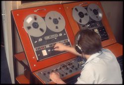
Audible Archives
Audible Archives
Actions:
Description:
Audible Archives presents samples of digitized recordings alongside silent artefacts from the CCA Collection, highlighting sound as a significant medium for research while drawing attention to the challenges of preservation and stewardship.
Audible Archives presents samples of digitized recordings alongside silent artefacts from the CCA Collection, highlighting sound as a significant medium for research while drawing attention to the challenges of preservation and stewardship.
Title:
Audible Archives
Actions:
Description:
Audible Archives presents samples of digitized recordings alongside silent artefacts from the CCA Collection, highlighting sound as a significant medium for research while drawing attention to the challenges of preservation and stewardship.
Audible Archives
Actions:
Description:
Audible Archives presents samples of digitized recordings alongside silent artefacts from the CCA Collection, highlighting sound as a significant medium for research while drawing attention to the challenges of preservation and stewardship.
Form:
exhibitions
exhibitions
Date:
18 December 2025 to
18 October 2026
18 December 2025 to
18 October 2026
Form:
born digital
born digital
Actions:
Reference number:
ARCH280967
Description:
Labelled "AutoCAD/NthView Digitizer drivers release 2.40 sample Zoomslide"
ARCH280967
Description:
Labelled "AutoCAD/NthView Digitizer drivers release 2.40 sample Zoomslide"
People:
Date:
circa 1988-1989
circa 1988-1989
Title:
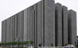
Various drawings of the provincial government building, Thunder Bay, Ontario, 5.25" floppy disk, 360 KB
Actions:
ARCH280967
Description:
Labelled "AutoCAD/NthView Digitizer drivers release 2.40 sample Zoomslide"
Various drawings of the provincial government building, Thunder Bay, Ontario, 5.25" floppy disk, 360 KB
Actions:
ARCH280967
Description:
Labelled "AutoCAD/NthView Digitizer drivers release 2.40 sample Zoomslide"
Form:
born digital
born digital
Date:
circa 1988-1989
circa 1988-1989
People:
Form:
research
research
Actions:
Description:
The CCA Virtual Fellowship Program supports our long-term investment in thinking through how already digitized and accessible CCA Collection material can generate new historical configurations, timely interpretations, and a broader reach within architectural research.
The CCA Virtual Fellowship Program supports our long-term investment in thinking through how already digitized and accessible CCA Collection material can generate new historical configurations, timely interpretations, and a broader reach within architectural research.
Keyword(s):
virtual fellowship program, Nokubekezela Mchunu, Wafa Ali, Papers that Remain, post-custodial archives, Africa
virtual fellowship program, Nokubekezela Mchunu, Wafa Ali, Papers that Remain, post-custodial archives, Africa
Date:
1 March 2022 to 23 December 2022
1 March 2022 to 23 December 2022
Title:
CCA Virtual Fellowship Program 2022
Actions:
Description:
The CCA Virtual Fellowship Program supports our long-term investment in thinking through how already digitized and accessible CCA Collection material can generate new historical configurations, timely interpretations, and a broader reach within architectural research.
Form:
research
research
Date:
1 March 2022 to
23 December 2022
1 March 2022 to
23 December 2022
Form:
articles
articles
Title:
Is a Database a Museum?
Is a Database a Museum?
Actions:
Level of archival description:
Series
Series
Title:
Presentation files
Presentation files
Actions:
Reference number:
AP195.S2
Description:
Series 2: Presentation files, 1999 – 2009, contains CAD files, 3D models, renderings, and photographs used for presentation of the Phaeno Science Centre, especially during the competition and design phases. Formats include chiefly images (EXIF, JPEG, TIFF) and CAD files (AutoCAD, plotter files, EPS). This series contains a wide variety of materials used by ZHA to present Phaeno Science Centre to clients, the press, and other stakeholders. This includes 3D models and CAD files, other drawings and diagrams, and photographs. Notably, this series includes concept animations used by ZHA to develop the shape and structure of Phaeno, as well as concept sketches possibly drawn by Zaha Hadid. Other materials of interest include a digitized copy of digital plans that had been printed and given a hand-painted rendering surface.
People:
Date:
1999 - 2009
1999 - 2009
Title:
Presentation files
Actions:
AP195.S2
Description:
Series 2: Presentation files, 1999 – 2009, contains CAD files, 3D models, renderings, and photographs used for presentation of the Phaeno Science Centre, especially during the competition and design phases. Formats include chiefly images (EXIF, JPEG, TIFF) and CAD files (AutoCAD, plotter files, EPS). This series contains a wide variety of materials used by ZHA to present Phaeno Science Centre to clients, the press, and other stakeholders. This includes 3D models and CAD files, other drawings and diagrams, and photographs. Notably, this series includes concept animations used by ZHA to develop the shape and structure of Phaeno, as well as concept sketches possibly drawn by Zaha Hadid. Other materials of interest include a digitized copy of digital plans that had been printed and given a hand-painted rendering surface.
Level of archival description:
Series
Series
Date:
1999 - 2009
1999 - 2009
People: