


27696 Results
Form:
drawings
drawings
Actions:
Reference number:
DR1990:0058
Description:
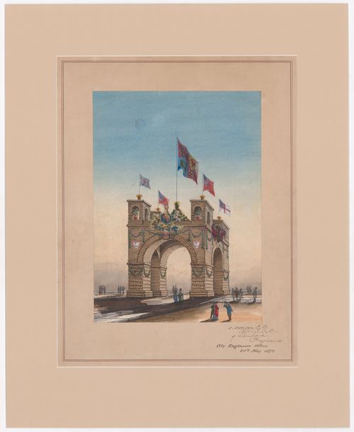
- This watercolour rendering depicts a welcome arch composed of four rounded arches which span the intersection of two streets. Construction materials were either stacked logs or materials simulating stacked logs. The arch is surmounted by log pavilions with arch openings and potted trees at each corner and a pile of agricultural produce in the center. The structure is embellished with shields, including two inscribed with "L", flags, the British royal coat of arms, and sheaves of wheat. Staffage indicates the large scale of the arch.
DR1990:0058
Description:
- This watercolour rendering depicts a welcome arch composed of four rounded arches which span the intersection of two streets. Construction materials were either stacked logs or materials simulating stacked logs. The arch is surmounted by log pavilions with arch openings and potted trees at each corner and a pile of agricultural produce in the center. The structure is embellished with shields, including two inscribed with "L", flags, the British royal coat of arms, and sheaves of wheat. Staffage indicates the large scale of the arch.
People:
Subject:
temporary architecture
temporary architecture
Date:
30 May 1879
30 May 1879
Title:
Perspective for a temporary welcome arch for the visit of the Marquess of Lorne and Princess Louise to Toronto, September 1879
Actions:
DR1990:0058
Description:
- This watercolour rendering depicts a welcome arch composed of four rounded arches which span the intersection of two streets. Construction materials were either stacked logs or materials simulating stacked logs. The arch is surmounted by log pavilions with arch openings and potted trees at each corner and a pile of agricultural produce in the center. The structure is embellished with shields, including two inscribed with "L", flags, the British royal coat of arms, and sheaves of wheat. Staffage indicates the large scale of the arch.
Perspective for a temporary welcome arch for the visit of the Marquess of Lorne and Princess Louise to Toronto, September 1879
Actions:
DR1990:0058
Description:
- This watercolour rendering depicts a welcome arch composed of four rounded arches which span the intersection of two streets. Construction materials were either stacked logs or materials simulating stacked logs. The arch is surmounted by log pavilions with arch openings and potted trees at each corner and a pile of agricultural produce in the center. The structure is embellished with shields, including two inscribed with "L", flags, the British royal coat of arms, and sheaves of wheat. Staffage indicates the large scale of the arch.
Form:
drawings
drawings
Date:
30 May 1879
30 May 1879
People:
Subject:
temporary architecture
temporary architecture
Form:
works of art
works of art
Reference number:
DR1988:0437:047
Description:
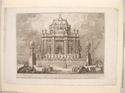
- This etching of a fireworks construction or macchina represents a public celebration of the making of a poison antidote "che si fà nella Città di Venezia" (as it is done in Venice). The macchina consists of a pavilion raised on a base. The pavilion appears to be square, with a central opening a large smoking vat of theriaca. The top storey appears to be octagonal and is crowned by a tent. The relief on the front of the octagon shows a view of the Piazza San Marco and the Doge's Palace from the Molo.
DR1988:0437:047
Description:
- This etching of a fireworks construction or macchina represents a public celebration of the making of a poison antidote "che si fà nella Città di Venezia" (as it is done in Venice). The macchina consists of a pavilion raised on a base. The pavilion appears to be square, with a central opening a large smoking vat of theriaca. The top storey appears to be octagonal and is crowned by a tent. The relief on the front of the octagon shows a view of the Piazza San Marco and the Doge's Palace from the Molo.
People:
Subject:
temporary architecture
temporary architecture
Date:
printed 1773
printed 1773
Title:
Etching of Posi's design for the "seconda macchina" of 1773
Actions:
DR1988:0437:047
Description:
- This etching of a fireworks construction or macchina represents a public celebration of the making of a poison antidote "che si fà nella Città di Venezia" (as it is done in Venice). The macchina consists of a pavilion raised on a base. The pavilion appears to be square, with a central opening a large smoking vat of theriaca. The top storey appears to be octagonal and is crowned by a tent. The relief on the front of the octagon shows a view of the Piazza San Marco and the Doge's Palace from the Molo.
Etching of Posi's design for the "seconda macchina" of 1773
Actions:
DR1988:0437:047
Description:
- This etching of a fireworks construction or macchina represents a public celebration of the making of a poison antidote "che si fà nella Città di Venezia" (as it is done in Venice). The macchina consists of a pavilion raised on a base. The pavilion appears to be square, with a central opening a large smoking vat of theriaca. The top storey appears to be octagonal and is crowned by a tent. The relief on the front of the octagon shows a view of the Piazza San Marco and the Doge's Palace from the Molo.
Form:
works of art
works of art
Date:
printed 1773
printed 1773
People:
Subject:
temporary architecture
temporary architecture
Form:
exhibitions
exhibitions
Actions:
Description:
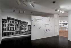
The greystone buildings standing in Montreal today are essential tools for understanding the city. A deep study of their material history from the late 17th century to the early 20th demonstrates how geology, topography, politics, ethnicity, culture, as well as changes in economy and technology, have shaped the city through the centuries. Conceived as a photographic(...)
The greystone buildings standing in Montreal today are essential tools for understanding the city. A deep study of their material history from the late 17th century to the early 20th demonstrates how geology, topography, politics, ethnicity, culture, as well as changes in economy and technology, have shaped the city through the centuries. Conceived as a photographic(...)
Location:
Octagonal gallery Keyword(s):
Greystone, Phyllis Lambert, Montréal, photography, Richard Pare
Octagonal gallery Keyword(s):
Greystone, Phyllis Lambert, Montréal, photography, Richard Pare
Date:
13 October 2017 to 4 March 2018
13 October 2017 to 4 March 2018
Title:
Greystone: Tools for Understanding the City
Actions:
Description:
The greystone buildings standing in Montreal today are essential tools for understanding the city. A deep study of their material history from the late 17th century to the early 20th demonstrates how geology, topography, politics, ethnicity, culture, as well as changes in economy and technology, have shaped the city through the centuries. Conceived as a photographic(...)
Greystone: Tools for Understanding the City
Actions:
Description:
The greystone buildings standing in Montreal today are essential tools for understanding the city. A deep study of their material history from the late 17th century to the early 20th demonstrates how geology, topography, politics, ethnicity, culture, as well as changes in economy and technology, have shaped the city through the centuries. Conceived as a photographic(...)
Form:
exhibitions
exhibitions
Date:
13 October 2017 to
4 March 2018
13 October 2017 to
4 March 2018
Location:
Octagonal gallery Keyword(s):
Greystone, Phyllis Lambert, Montréal, photography, Richard Pare
Octagonal gallery Keyword(s):
Greystone, Phyllis Lambert, Montréal, photography, Richard Pare
Form:
articles
articles

Actions:
Keyword(s):
18th century, 19th century, Antiquité, antiquité, Antiquity, Buffon, Charles de Wailly, Charles-François Viel, Claude-Nicolas Ledoux, dessin, drawing, Etienne-Louis Boullée, Étienne-Louis Boullée, France, French Revolution, Grèce, Greece, hôpital, hospital, Jacques-Germain Soufflot, Jean-Louis Viel de Saint-Maux, Jean-Nicolas-Louis Durand, Lettres d’architecture des anciens et celle des moderns, Panthéon, Paris, Paul Holmquist, Principes de l’ordonnance et de la construction des bâtimens, Renaissance, Révolution française, Rome, Sainte-Geneviève, Vitruve,
18th century, 19th century, Antiquité, antiquité, Antiquity, Buffon, Charles de Wailly, Charles-François Viel, Claude-Nicolas Ledoux, dessin, drawing, Etienne-Louis Boullée, Étienne-Louis Boullée, France, French Revolution, Grèce, Greece, hôpital, hospital, Jacques-Germain Soufflot, Jean-Louis Viel de Saint-Maux, Jean-Nicolas-Louis Durand, Lettres d’architecture des anciens et celle des moderns, Panthéon, Paris, Paul Holmquist, Principes de l’ordonnance et de la construction des bâtimens, Renaissance, Révolution française, Rome, Sainte-Geneviève, Vitruve,
Published:
28 November 2011
28 November 2011
Form:
photographs
photographs
Actions:
Reference number:
PH1987:0990
Description:
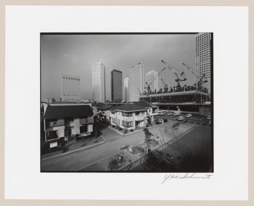
- This photograph shows several notable high-rise buildings, from left to right, the Century Hyatt Tokyo hotel, the Shinjuku Sumitomo Building, the Shinjuku Mitsui Building, the Shinjuku Nomura Building, the Keio Plaza Hotel (also known as the North Building), the Keio Plaza South Building and the KDDI Building, with the Shinjuku NS Building under construction at right. - Westerbeck reproduces a comparable photograph by Yasuhiro Ishimoto, dated "1987", showing a similar view but with the Shinjuku NS Building in a completed state (Westerbeck, p. 131, repr.).
PH1987:0990
Description:
- This photograph shows several notable high-rise buildings, from left to right, the Century Hyatt Tokyo hotel, the Shinjuku Sumitomo Building, the Shinjuku Mitsui Building, the Shinjuku Nomura Building, the Keio Plaza Hotel (also known as the North Building), the Keio Plaza South Building and the KDDI Building, with the Shinjuku NS Building under construction at right. - Westerbeck reproduces a comparable photograph by Yasuhiro Ishimoto, dated "1987", showing a similar view but with the Shinjuku NS Building in a completed state (Westerbeck, p. 131, repr.).
People:
Subject:
architecture
architecture
Date:
between 1979 and 1982
between 1979 and 1982
Title:
View of central Shinjuku-ku, Tokyo, Japan
Actions:
PH1987:0990
Description:
- This photograph shows several notable high-rise buildings, from left to right, the Century Hyatt Tokyo hotel, the Shinjuku Sumitomo Building, the Shinjuku Mitsui Building, the Shinjuku Nomura Building, the Keio Plaza Hotel (also known as the North Building), the Keio Plaza South Building and the KDDI Building, with the Shinjuku NS Building under construction at right. - Westerbeck reproduces a comparable photograph by Yasuhiro Ishimoto, dated "1987", showing a similar view but with the Shinjuku NS Building in a completed state (Westerbeck, p. 131, repr.).
View of central Shinjuku-ku, Tokyo, Japan
Actions:
PH1987:0990
Description:
- This photograph shows several notable high-rise buildings, from left to right, the Century Hyatt Tokyo hotel, the Shinjuku Sumitomo Building, the Shinjuku Mitsui Building, the Shinjuku Nomura Building, the Keio Plaza Hotel (also known as the North Building), the Keio Plaza South Building and the KDDI Building, with the Shinjuku NS Building under construction at right. - Westerbeck reproduces a comparable photograph by Yasuhiro Ishimoto, dated "1987", showing a similar view but with the Shinjuku NS Building in a completed state (Westerbeck, p. 131, repr.).
Form:
photographs
photographs
Date:
between 1979 and 1982
between 1979 and 1982
People:
Subject:
architecture
architecture
Form:
drawings, textual records
drawings, textual records
Reference number:
ARCH267676
Description:
Sketches by Pierre Jeanneret depicting studies for dwelling(s) and other building(s), including plans, facades, details, and building materials, as well as furniture. Some sketches are annotated by the artist and include mathematical calculations. It is likely that sketche(s) depict buildings in Chandigarh, India. Further research is required. Also contains: - A drawing depicting a colossus with a foot in Chandigarh and a foot in Durgapur. - Notes pertaning to the construction and design of unidentified buildings. - Notes pertaining to the use of building materials.
ARCH267676
Description:
Sketches by Pierre Jeanneret depicting studies for dwelling(s) and other building(s), including plans, facades, details, and building materials, as well as furniture. Some sketches are annotated by the artist and include mathematical calculations. It is likely that sketche(s) depict buildings in Chandigarh, India. Further research is required. Also contains: - A drawing depicting a colossus with a foot in Chandigarh and a foot in Durgapur. - Notes pertaning to the construction and design of unidentified buildings. - Notes pertaining to the use of building materials.
People:
Date:
between 1951-1962
between 1951-1962
Title:
Sketches by Pierre Jeanneret depicting studies for dwelling(s) and other building(s)
Actions:
ARCH267676
Description:
Sketches by Pierre Jeanneret depicting studies for dwelling(s) and other building(s), including plans, facades, details, and building materials, as well as furniture. Some sketches are annotated by the artist and include mathematical calculations. It is likely that sketche(s) depict buildings in Chandigarh, India. Further research is required. Also contains: - A drawing depicting a colossus with a foot in Chandigarh and a foot in Durgapur. - Notes pertaning to the construction and design of unidentified buildings. - Notes pertaining to the use of building materials.
Sketches by Pierre Jeanneret depicting studies for dwelling(s) and other building(s)
Actions:
ARCH267676
Description:
Sketches by Pierre Jeanneret depicting studies for dwelling(s) and other building(s), including plans, facades, details, and building materials, as well as furniture. Some sketches are annotated by the artist and include mathematical calculations. It is likely that sketche(s) depict buildings in Chandigarh, India. Further research is required. Also contains: - A drawing depicting a colossus with a foot in Chandigarh and a foot in Durgapur. - Notes pertaning to the construction and design of unidentified buildings. - Notes pertaining to the use of building materials.
Form:
drawings, textual records
drawings, textual records
Date:
between 1951-1962
between 1951-1962
People:
Level of archival description:
Project
Project
Title:
Weavers' Studio
Weavers' Studio
Reference number:
AP182.S1.2013.D2
Description:
File documents a project for a live-work complex in Dehradun, Uttarakhand, India. Commissioned by Chiaki Maki, a Japanese textile weaver who spends a portion of each year in northern India, this complex in the Himalayan foothills provides working space for a studio of twenty-five weavers from all over the country. It is conceived as a cyclical, self-sufficient farm system that integrates all aspects of the weaving process, from cultivating indigo and henna for dye to gathering silk from cocoons and spinning wool. The site had been previously cultivated, and the design works with the landscape's existing pathways, terraces, and mango groves. Nearly all construction materials--including the brick, limestone, and phosphorescent river stones used in the foundation and to treat the brick walls--come from within a two-kilometre radius of the studio. The five-sided building occupying the centre of the site is the workshop itself, which frames a courtyard for gatherings (of weavers, children, etc.). A gallery in the complex displays the weavers' work, while the linear buildings accommodate motorcycle parking, a guest house, and residences for Maki and her partner as well as the site caretaker and his family. File contains artefacts and realia, models, photographs, drawings, site reports, and a video recording.
AP182.S1.2013.D2
Description:
File documents a project for a live-work complex in Dehradun, Uttarakhand, India. Commissioned by Chiaki Maki, a Japanese textile weaver who spends a portion of each year in northern India, this complex in the Himalayan foothills provides working space for a studio of twenty-five weavers from all over the country. It is conceived as a cyclical, self-sufficient farm system that integrates all aspects of the weaving process, from cultivating indigo and henna for dye to gathering silk from cocoons and spinning wool. The site had been previously cultivated, and the design works with the landscape's existing pathways, terraces, and mango groves. Nearly all construction materials--including the brick, limestone, and phosphorescent river stones used in the foundation and to treat the brick walls--come from within a two-kilometre radius of the studio. The five-sided building occupying the centre of the site is the workshop itself, which frames a courtyard for gatherings (of weavers, children, etc.). A gallery in the complex displays the weavers' work, while the linear buildings accommodate motorcycle parking, a guest house, and residences for Maki and her partner as well as the site caretaker and his family. File contains artefacts and realia, models, photographs, drawings, site reports, and a video recording.
People:
Date:
2012-2015
2012-2015
Title:
Weavers' Studio
Actions:
AP182.S1.2013.D2
Description:
File documents a project for a live-work complex in Dehradun, Uttarakhand, India. Commissioned by Chiaki Maki, a Japanese textile weaver who spends a portion of each year in northern India, this complex in the Himalayan foothills provides working space for a studio of twenty-five weavers from all over the country. It is conceived as a cyclical, self-sufficient farm system that integrates all aspects of the weaving process, from cultivating indigo and henna for dye to gathering silk from cocoons and spinning wool. The site had been previously cultivated, and the design works with the landscape's existing pathways, terraces, and mango groves. Nearly all construction materials--including the brick, limestone, and phosphorescent river stones used in the foundation and to treat the brick walls--come from within a two-kilometre radius of the studio. The five-sided building occupying the centre of the site is the workshop itself, which frames a courtyard for gatherings (of weavers, children, etc.). A gallery in the complex displays the weavers' work, while the linear buildings accommodate motorcycle parking, a guest house, and residences for Maki and her partner as well as the site caretaker and his family. File contains artefacts and realia, models, photographs, drawings, site reports, and a video recording.
Weavers' Studio
Actions:
AP182.S1.2013.D2
Description:
File documents a project for a live-work complex in Dehradun, Uttarakhand, India. Commissioned by Chiaki Maki, a Japanese textile weaver who spends a portion of each year in northern India, this complex in the Himalayan foothills provides working space for a studio of twenty-five weavers from all over the country. It is conceived as a cyclical, self-sufficient farm system that integrates all aspects of the weaving process, from cultivating indigo and henna for dye to gathering silk from cocoons and spinning wool. The site had been previously cultivated, and the design works with the landscape's existing pathways, terraces, and mango groves. Nearly all construction materials--including the brick, limestone, and phosphorescent river stones used in the foundation and to treat the brick walls--come from within a two-kilometre radius of the studio. The five-sided building occupying the centre of the site is the workshop itself, which frames a courtyard for gatherings (of weavers, children, etc.). A gallery in the complex displays the weavers' work, while the linear buildings accommodate motorcycle parking, a guest house, and residences for Maki and her partner as well as the site caretaker and his family. File contains artefacts and realia, models, photographs, drawings, site reports, and a video recording.
Level of archival description:
Project
Project
Date:
2012-2015
2012-2015
People:
Level of archival description:
Project
Project
Reference number:
AP075.S1.1986.PR08
Description:
Project series documents Cornelia Hahn Oberlander's landscape project for the Russell Residence in Lake Bay, near in Tacoma, Washington, United States. Oberlander worked on this project in 1986-1989 with architect Arthur Erickson. The project consisted in building a new house and garden on the 300 acres family farm, located on a promotery overlooking Puget Sound. The landscape design included the planting of rhododendrons nestled into the woodland along one side of the looped drive leading to a parking area, and an herbs and vegetables garden next to the house, near the dining room. Oberlander created a meadow area at the centre of the loop entrance drive with spring bulbs and summer wildflowers providing interest at all seasons. The project was completed in 1989. The project series contains sketches, design development drawings, including plans of the herbs and vegetables gardens, planting plans and schematic landscape plans, and working drawings, including planting plans, site plans and grading plans. The project is also documented through Oberlander's concept notes, research material, landscape specifications, correspondence with client and architects, and financial documents. The project series also comprises photographs of Cornelia Hahn Oberlander and other visiting the site, and photographs of the construction of the residence and landspace work.
AP075.S1.1986.PR08
Description:
Project series documents Cornelia Hahn Oberlander's landscape project for the Russell Residence in Lake Bay, near in Tacoma, Washington, United States. Oberlander worked on this project in 1986-1989 with architect Arthur Erickson. The project consisted in building a new house and garden on the 300 acres family farm, located on a promotery overlooking Puget Sound. The landscape design included the planting of rhododendrons nestled into the woodland along one side of the looped drive leading to a parking area, and an herbs and vegetables garden next to the house, near the dining room. Oberlander created a meadow area at the centre of the loop entrance drive with spring bulbs and summer wildflowers providing interest at all seasons. The project was completed in 1989. The project series contains sketches, design development drawings, including plans of the herbs and vegetables gardens, planting plans and schematic landscape plans, and working drawings, including planting plans, site plans and grading plans. The project is also documented through Oberlander's concept notes, research material, landscape specifications, correspondence with client and architects, and financial documents. The project series also comprises photographs of Cornelia Hahn Oberlander and other visiting the site, and photographs of the construction of the residence and landspace work.
People:
Date:
1985-1998
1985-1998
Title:
Russell Residence, Tacoma, Washington (1986)
Actions:
AP075.S1.1986.PR08
Description:
Project series documents Cornelia Hahn Oberlander's landscape project for the Russell Residence in Lake Bay, near in Tacoma, Washington, United States. Oberlander worked on this project in 1986-1989 with architect Arthur Erickson. The project consisted in building a new house and garden on the 300 acres family farm, located on a promotery overlooking Puget Sound. The landscape design included the planting of rhododendrons nestled into the woodland along one side of the looped drive leading to a parking area, and an herbs and vegetables garden next to the house, near the dining room. Oberlander created a meadow area at the centre of the loop entrance drive with spring bulbs and summer wildflowers providing interest at all seasons. The project was completed in 1989. The project series contains sketches, design development drawings, including plans of the herbs and vegetables gardens, planting plans and schematic landscape plans, and working drawings, including planting plans, site plans and grading plans. The project is also documented through Oberlander's concept notes, research material, landscape specifications, correspondence with client and architects, and financial documents. The project series also comprises photographs of Cornelia Hahn Oberlander and other visiting the site, and photographs of the construction of the residence and landspace work.
Russell Residence, Tacoma, Washington (1986)
Actions:
AP075.S1.1986.PR08
Description:
Project series documents Cornelia Hahn Oberlander's landscape project for the Russell Residence in Lake Bay, near in Tacoma, Washington, United States. Oberlander worked on this project in 1986-1989 with architect Arthur Erickson. The project consisted in building a new house and garden on the 300 acres family farm, located on a promotery overlooking Puget Sound. The landscape design included the planting of rhododendrons nestled into the woodland along one side of the looped drive leading to a parking area, and an herbs and vegetables garden next to the house, near the dining room. Oberlander created a meadow area at the centre of the loop entrance drive with spring bulbs and summer wildflowers providing interest at all seasons. The project was completed in 1989. The project series contains sketches, design development drawings, including plans of the herbs and vegetables gardens, planting plans and schematic landscape plans, and working drawings, including planting plans, site plans and grading plans. The project is also documented through Oberlander's concept notes, research material, landscape specifications, correspondence with client and architects, and financial documents. The project series also comprises photographs of Cornelia Hahn Oberlander and other visiting the site, and photographs of the construction of the residence and landspace work.
Level of archival description:
Project
Project
Date:
1985-1998
1985-1998
People:
Level of archival description:
Project
Project
Title:
Leal, Porto
Leal, Porto
Actions:
Reference number:
CD034.S1.1974.PR02
Description:
This project series contains eight reproductions of drawings displayed in the exhibit to document the Leal neighbourhood, in Porto, Portugal. The exhibit text explained that the project: ... pioneered the concept of community association, with the first resident activities dating back to the early 1970s. In 1974, immediately after the revolution, the residents opposed the building of a car park that would have involved their relocation and resettlement. The project of the architect Sérgio Fernandez, which originated in a pre-revolutionary resident organization, was conceived through the dynamics of the resident process, and had a project-oriented clarity that came from an economic sense of design, adapting to the needs and political character of the intervention. (The SAAL Process, Housing in Portugal 1974–76) Sérgio Fernandez worked for SAAL/North with António Corte Real, Carlos Delfim, Emídio Fonseca, José Manuel Soares, Vítor Sinde and the residents' association Bairro do Leal, that was founded on April 30th, 1975. The first phase of the project included 16 dwellings and the second, 33 dwellings. The operation began in October 1974, with a construction date in April 1976. This project series contains reproductions of design development drawings, cadastral and implementation plans, and an axonometric view. The original drawings were produced in 1975 and were reproduced in 2015 for the exhibit.
CD034.S1.1974.PR02
Description:
This project series contains eight reproductions of drawings displayed in the exhibit to document the Leal neighbourhood, in Porto, Portugal. The exhibit text explained that the project: ... pioneered the concept of community association, with the first resident activities dating back to the early 1970s. In 1974, immediately after the revolution, the residents opposed the building of a car park that would have involved their relocation and resettlement. The project of the architect Sérgio Fernandez, which originated in a pre-revolutionary resident organization, was conceived through the dynamics of the resident process, and had a project-oriented clarity that came from an economic sense of design, adapting to the needs and political character of the intervention. (The SAAL Process, Housing in Portugal 1974–76) Sérgio Fernandez worked for SAAL/North with António Corte Real, Carlos Delfim, Emídio Fonseca, José Manuel Soares, Vítor Sinde and the residents' association Bairro do Leal, that was founded on April 30th, 1975. The first phase of the project included 16 dwellings and the second, 33 dwellings. The operation began in October 1974, with a construction date in April 1976. This project series contains reproductions of design development drawings, cadastral and implementation plans, and an axonometric view. The original drawings were produced in 1975 and were reproduced in 2015 for the exhibit.
People:
Date:
1975
1975
Title:
Leal, Porto
Actions:
CD034.S1.1974.PR02
Description:
This project series contains eight reproductions of drawings displayed in the exhibit to document the Leal neighbourhood, in Porto, Portugal. The exhibit text explained that the project: ... pioneered the concept of community association, with the first resident activities dating back to the early 1970s. In 1974, immediately after the revolution, the residents opposed the building of a car park that would have involved their relocation and resettlement. The project of the architect Sérgio Fernandez, which originated in a pre-revolutionary resident organization, was conceived through the dynamics of the resident process, and had a project-oriented clarity that came from an economic sense of design, adapting to the needs and political character of the intervention. (The SAAL Process, Housing in Portugal 1974–76) Sérgio Fernandez worked for SAAL/North with António Corte Real, Carlos Delfim, Emídio Fonseca, José Manuel Soares, Vítor Sinde and the residents' association Bairro do Leal, that was founded on April 30th, 1975. The first phase of the project included 16 dwellings and the second, 33 dwellings. The operation began in October 1974, with a construction date in April 1976. This project series contains reproductions of design development drawings, cadastral and implementation plans, and an axonometric view. The original drawings were produced in 1975 and were reproduced in 2015 for the exhibit.
Leal, Porto
Actions:
CD034.S1.1974.PR02
Description:
This project series contains eight reproductions of drawings displayed in the exhibit to document the Leal neighbourhood, in Porto, Portugal. The exhibit text explained that the project: ... pioneered the concept of community association, with the first resident activities dating back to the early 1970s. In 1974, immediately after the revolution, the residents opposed the building of a car park that would have involved their relocation and resettlement. The project of the architect Sérgio Fernandez, which originated in a pre-revolutionary resident organization, was conceived through the dynamics of the resident process, and had a project-oriented clarity that came from an economic sense of design, adapting to the needs and political character of the intervention. (The SAAL Process, Housing in Portugal 1974–76) Sérgio Fernandez worked for SAAL/North with António Corte Real, Carlos Delfim, Emídio Fonseca, José Manuel Soares, Vítor Sinde and the residents' association Bairro do Leal, that was founded on April 30th, 1975. The first phase of the project included 16 dwellings and the second, 33 dwellings. The operation began in October 1974, with a construction date in April 1976. This project series contains reproductions of design development drawings, cadastral and implementation plans, and an axonometric view. The original drawings were produced in 1975 and were reproduced in 2015 for the exhibit.
Level of archival description:
Project
Project
Date:
1975
1975
People:
Form:
drawings
Quantity:
4 drawing(s)
drawings
Quantity:
4 drawing(s)
Reference number:
DR1995:0172:001-004
Description:
This project for two designs for the Architectural Association's dining room includes a display table (DR1995:0172:001 - DR1995:0172:002) and a service table (DR1995:0172:003 - DR1995:0172:004). All drawings show fully developed construction details along with plan, elevation, and section views. The display table design indicates an additional shelf, possibly an additional display surface. The service table design was apparently to be used for food service since an upper "bar shelf" and "hot-plate" are indicated.
DR1995:0172:001-004
Description:
This project for two designs for the Architectural Association's dining room includes a display table (DR1995:0172:001 - DR1995:0172:002) and a service table (DR1995:0172:003 - DR1995:0172:004). All drawings show fully developed construction details along with plan, elevation, and section views. The display table design indicates an additional shelf, possibly an additional display surface. The service table design was apparently to be used for food service since an upper "bar shelf" and "hot-plate" are indicated.
People:
Date:
1957
1957
Title:
Display and service table for the Architectural Association dining room, London: Furniture design drawings
Actions:
DR1995:0172:001-004
Description:
This project for two designs for the Architectural Association's dining room includes a display table (DR1995:0172:001 - DR1995:0172:002) and a service table (DR1995:0172:003 - DR1995:0172:004). All drawings show fully developed construction details along with plan, elevation, and section views. The display table design indicates an additional shelf, possibly an additional display surface. The service table design was apparently to be used for food service since an upper "bar shelf" and "hot-plate" are indicated.
Display and service table for the Architectural Association dining room, London: Furniture design drawings
Actions:
DR1995:0172:001-004
Description:
This project for two designs for the Architectural Association's dining room includes a display table (DR1995:0172:001 - DR1995:0172:002) and a service table (DR1995:0172:003 - DR1995:0172:004). All drawings show fully developed construction details along with plan, elevation, and section views. The display table design indicates an additional shelf, possibly an additional display surface. The service table design was apparently to be used for food service since an upper "bar shelf" and "hot-plate" are indicated.
Form:
drawings
Quantity:
4 drawing(s)
drawings
Quantity:
4 drawing(s)
Date:
1957
1957
People:


