


36938 Results
Level of archival description:
Series
Series
Title:
Project records from Mr. Koz
Project records from Mr. Koz
Actions:
Reference number:
AP168.S2
Description:
The Project records from Mr. Koz series, 1996, consists of records produced by Seiichi Kozu of Studio KOZ, a local architect who managed the physical construction and installation of Denari’s show “Interrupted Projections” at Gallery MA in Tokyo, Japan. The series consists of 20 drawings and/or reprographic copies, 19 layouts, 16 slides, and a small amount of promotional material including three posters and one promotional pamphlet. Records date from 1996. For Interrupted Projections, in collaboration with Tokyo-based architect Seiichi Kozu (Mr. Koz) of Studio KOZ, Denari used traditional construction techniques to build a structure inside the gallery space that blended floor, wall and ceiling into a continuous curved surface. This surface displayed printed logos for fictional corporations, designed specifically for the exhibition. The majority of drawings and reprographic copies in the series relate to the construction of the principal architectural installation built on the third floor of Gallery MA. This includes plans and sections for the third floor, as well as working drawings that detail specifications such as dimensions, materials, layouts, and assembly techniques. The series also contains a set of five drawings that include first and second floor plans and sections of Gallery MA. The majority of writing on the drawings is Japanese, aside from one reprographic copy with third floor plans and sections that contains notes in English about elements of the installation such as lighting and the placement and size of fictional company logos. Photographic materials in the series comprise 16 slides that contain images of the built installation, as well as images of the exhibition open to the public, including slides of visitors interacting with the NaviCam. The series also includes printed layouts of the 3D digital renderings for the Interrupted Projections model alongside a pantone sheet, which were used as a reference during the construction process. Promotional material in the series includes three small posters for the exhibition, as well as a brochure that highlights selected works from the show.
AP168.S2
Description:
The Project records from Mr. Koz series, 1996, consists of records produced by Seiichi Kozu of Studio KOZ, a local architect who managed the physical construction and installation of Denari’s show “Interrupted Projections” at Gallery MA in Tokyo, Japan. The series consists of 20 drawings and/or reprographic copies, 19 layouts, 16 slides, and a small amount of promotional material including three posters and one promotional pamphlet. Records date from 1996. For Interrupted Projections, in collaboration with Tokyo-based architect Seiichi Kozu (Mr. Koz) of Studio KOZ, Denari used traditional construction techniques to build a structure inside the gallery space that blended floor, wall and ceiling into a continuous curved surface. This surface displayed printed logos for fictional corporations, designed specifically for the exhibition. The majority of drawings and reprographic copies in the series relate to the construction of the principal architectural installation built on the third floor of Gallery MA. This includes plans and sections for the third floor, as well as working drawings that detail specifications such as dimensions, materials, layouts, and assembly techniques. The series also contains a set of five drawings that include first and second floor plans and sections of Gallery MA. The majority of writing on the drawings is Japanese, aside from one reprographic copy with third floor plans and sections that contains notes in English about elements of the installation such as lighting and the placement and size of fictional company logos. Photographic materials in the series comprise 16 slides that contain images of the built installation, as well as images of the exhibition open to the public, including slides of visitors interacting with the NaviCam. The series also includes printed layouts of the 3D digital renderings for the Interrupted Projections model alongside a pantone sheet, which were used as a reference during the construction process. Promotional material in the series includes three small posters for the exhibition, as well as a brochure that highlights selected works from the show.
People:
Date:
1996
1996
Title:
Project records from Mr. Koz
Actions:
AP168.S2
Description:
The Project records from Mr. Koz series, 1996, consists of records produced by Seiichi Kozu of Studio KOZ, a local architect who managed the physical construction and installation of Denari’s show “Interrupted Projections” at Gallery MA in Tokyo, Japan. The series consists of 20 drawings and/or reprographic copies, 19 layouts, 16 slides, and a small amount of promotional material including three posters and one promotional pamphlet. Records date from 1996. For Interrupted Projections, in collaboration with Tokyo-based architect Seiichi Kozu (Mr. Koz) of Studio KOZ, Denari used traditional construction techniques to build a structure inside the gallery space that blended floor, wall and ceiling into a continuous curved surface. This surface displayed printed logos for fictional corporations, designed specifically for the exhibition. The majority of drawings and reprographic copies in the series relate to the construction of the principal architectural installation built on the third floor of Gallery MA. This includes plans and sections for the third floor, as well as working drawings that detail specifications such as dimensions, materials, layouts, and assembly techniques. The series also contains a set of five drawings that include first and second floor plans and sections of Gallery MA. The majority of writing on the drawings is Japanese, aside from one reprographic copy with third floor plans and sections that contains notes in English about elements of the installation such as lighting and the placement and size of fictional company logos. Photographic materials in the series comprise 16 slides that contain images of the built installation, as well as images of the exhibition open to the public, including slides of visitors interacting with the NaviCam. The series also includes printed layouts of the 3D digital renderings for the Interrupted Projections model alongside a pantone sheet, which were used as a reference during the construction process. Promotional material in the series includes three small posters for the exhibition, as well as a brochure that highlights selected works from the show.
Project records from Mr. Koz
Actions:
AP168.S2
Description:
The Project records from Mr. Koz series, 1996, consists of records produced by Seiichi Kozu of Studio KOZ, a local architect who managed the physical construction and installation of Denari’s show “Interrupted Projections” at Gallery MA in Tokyo, Japan. The series consists of 20 drawings and/or reprographic copies, 19 layouts, 16 slides, and a small amount of promotional material including three posters and one promotional pamphlet. Records date from 1996. For Interrupted Projections, in collaboration with Tokyo-based architect Seiichi Kozu (Mr. Koz) of Studio KOZ, Denari used traditional construction techniques to build a structure inside the gallery space that blended floor, wall and ceiling into a continuous curved surface. This surface displayed printed logos for fictional corporations, designed specifically for the exhibition. The majority of drawings and reprographic copies in the series relate to the construction of the principal architectural installation built on the third floor of Gallery MA. This includes plans and sections for the third floor, as well as working drawings that detail specifications such as dimensions, materials, layouts, and assembly techniques. The series also contains a set of five drawings that include first and second floor plans and sections of Gallery MA. The majority of writing on the drawings is Japanese, aside from one reprographic copy with third floor plans and sections that contains notes in English about elements of the installation such as lighting and the placement and size of fictional company logos. Photographic materials in the series comprise 16 slides that contain images of the built installation, as well as images of the exhibition open to the public, including slides of visitors interacting with the NaviCam. The series also includes printed layouts of the 3D digital renderings for the Interrupted Projections model alongside a pantone sheet, which were used as a reference during the construction process. Promotional material in the series includes three small posters for the exhibition, as well as a brochure that highlights selected works from the show.
Level of archival description:
Series
Series
Date:
1996
1996
People:
Form:
photographs
photographs
Actions:
Reference number:
PH1979:0162.03:001-032
Description:
This unbound album comprises 32 photographs (incomplete, missing .33, .34, .35 according to List of plates), title pages and a list of plates (as follows): Le Nouvel Opéra de Paris. Statues décoratives Le Nouvel Opéra de Paris. Statues décoratives. Groupes et bas-reliefs par Charles Garnier, architecte, membre de l'Institut D et Cie, Paris, Librairie Générale de l'Architecture et des Travaux Publics, Ducher et Cie Éditeurs, 51, rue des Écoles, 51, 1875 Table des Planches Groupes de la façade principale 1. - La danse - Carpeaux 2. - La Poésie - Jouffroy 3. - Le Drame - Perraud 4. - La Musique - Guillaume 5. - Apollon - Millet 6. - Pégase - Lequesne 7. - Pégase - Lequesne Statues dans le Grand Foyer 8. - L'Imagination - Bourgeois 9. - La Beauté - Soitoux 10. - La Grâce - Loison 11. - La Pensée - Franceschi 12. - La Dignité - Sanzel 13. - L'Indépendance - Varnier 14. - La Fantaisie - Chambard 15. - La Passion - Debut 16. - La Foi - Olliva 17. - L'Élégance - Iselin 18. - La Philosophie - Tournois 19. - La Modération - Gauthier 20. - L'Espérance - Bruyer 21. - La Force - Eude 22. - La Sagesse - Talluet 23. - La Volonté - Janson 24. - La Prudence - Frison 25. - La Tradition - Cambos 26. - La Science - Marcelin 27. - La Modestie - Vilain Dessus de portes de l'avant-foyer 28. - Pavage et Gaz - Cugnot 29. - Plomberie et Taille de pierre - Guitton 30. - Peinture et Fumisterie - Chevalier 31. - Terrasse et Charpente - Delaplanche 32. - Tapisserie et Menuiserie - Vital-Dubray 33. - Maçonnerie et Serrurerie - Barrias 34. - Mosaïque et Mécanique - Mathieu-Meunier 35. - Arc doubleau de la scène - Chabaud
PH1979:0162.03:001-032
Description:
This unbound album comprises 32 photographs (incomplete, missing .33, .34, .35 according to List of plates), title pages and a list of plates (as follows): Le Nouvel Opéra de Paris. Statues décoratives Le Nouvel Opéra de Paris. Statues décoratives. Groupes et bas-reliefs par Charles Garnier, architecte, membre de l'Institut D et Cie, Paris, Librairie Générale de l'Architecture et des Travaux Publics, Ducher et Cie Éditeurs, 51, rue des Écoles, 51, 1875 Table des Planches Groupes de la façade principale 1. - La danse - Carpeaux 2. - La Poésie - Jouffroy 3. - Le Drame - Perraud 4. - La Musique - Guillaume 5. - Apollon - Millet 6. - Pégase - Lequesne 7. - Pégase - Lequesne Statues dans le Grand Foyer 8. - L'Imagination - Bourgeois 9. - La Beauté - Soitoux 10. - La Grâce - Loison 11. - La Pensée - Franceschi 12. - La Dignité - Sanzel 13. - L'Indépendance - Varnier 14. - La Fantaisie - Chambard 15. - La Passion - Debut 16. - La Foi - Olliva 17. - L'Élégance - Iselin 18. - La Philosophie - Tournois 19. - La Modération - Gauthier 20. - L'Espérance - Bruyer 21. - La Force - Eude 22. - La Sagesse - Talluet 23. - La Volonté - Janson 24. - La Prudence - Frison 25. - La Tradition - Cambos 26. - La Science - Marcelin 27. - La Modestie - Vilain Dessus de portes de l'avant-foyer 28. - Pavage et Gaz - Cugnot 29. - Plomberie et Taille de pierre - Guitton 30. - Peinture et Fumisterie - Chevalier 31. - Terrasse et Charpente - Delaplanche 32. - Tapisserie et Menuiserie - Vital-Dubray 33. - Maçonnerie et Serrurerie - Barrias 34. - Mosaïque et Mécanique - Mathieu-Meunier 35. - Arc doubleau de la scène - Chabaud
People:
Date:
published 1875
published 1875
Title:
Le Nouvel Opéra de Paris. Statues Décoratives. Groupes et Bas-reliefs par Charles Garnier
Actions:
PH1979:0162.03:001-032
Description:
This unbound album comprises 32 photographs (incomplete, missing .33, .34, .35 according to List of plates), title pages and a list of plates (as follows): Le Nouvel Opéra de Paris. Statues décoratives Le Nouvel Opéra de Paris. Statues décoratives. Groupes et bas-reliefs par Charles Garnier, architecte, membre de l'Institut D et Cie, Paris, Librairie Générale de l'Architecture et des Travaux Publics, Ducher et Cie Éditeurs, 51, rue des Écoles, 51, 1875 Table des Planches Groupes de la façade principale 1. - La danse - Carpeaux 2. - La Poésie - Jouffroy 3. - Le Drame - Perraud 4. - La Musique - Guillaume 5. - Apollon - Millet 6. - Pégase - Lequesne 7. - Pégase - Lequesne Statues dans le Grand Foyer 8. - L'Imagination - Bourgeois 9. - La Beauté - Soitoux 10. - La Grâce - Loison 11. - La Pensée - Franceschi 12. - La Dignité - Sanzel 13. - L'Indépendance - Varnier 14. - La Fantaisie - Chambard 15. - La Passion - Debut 16. - La Foi - Olliva 17. - L'Élégance - Iselin 18. - La Philosophie - Tournois 19. - La Modération - Gauthier 20. - L'Espérance - Bruyer 21. - La Force - Eude 22. - La Sagesse - Talluet 23. - La Volonté - Janson 24. - La Prudence - Frison 25. - La Tradition - Cambos 26. - La Science - Marcelin 27. - La Modestie - Vilain Dessus de portes de l'avant-foyer 28. - Pavage et Gaz - Cugnot 29. - Plomberie et Taille de pierre - Guitton 30. - Peinture et Fumisterie - Chevalier 31. - Terrasse et Charpente - Delaplanche 32. - Tapisserie et Menuiserie - Vital-Dubray 33. - Maçonnerie et Serrurerie - Barrias 34. - Mosaïque et Mécanique - Mathieu-Meunier 35. - Arc doubleau de la scène - Chabaud
Le Nouvel Opéra de Paris. Statues Décoratives. Groupes et Bas-reliefs par Charles Garnier
Actions:
PH1979:0162.03:001-032
Description:
This unbound album comprises 32 photographs (incomplete, missing .33, .34, .35 according to List of plates), title pages and a list of plates (as follows): Le Nouvel Opéra de Paris. Statues décoratives Le Nouvel Opéra de Paris. Statues décoratives. Groupes et bas-reliefs par Charles Garnier, architecte, membre de l'Institut D et Cie, Paris, Librairie Générale de l'Architecture et des Travaux Publics, Ducher et Cie Éditeurs, 51, rue des Écoles, 51, 1875 Table des Planches Groupes de la façade principale 1. - La danse - Carpeaux 2. - La Poésie - Jouffroy 3. - Le Drame - Perraud 4. - La Musique - Guillaume 5. - Apollon - Millet 6. - Pégase - Lequesne 7. - Pégase - Lequesne Statues dans le Grand Foyer 8. - L'Imagination - Bourgeois 9. - La Beauté - Soitoux 10. - La Grâce - Loison 11. - La Pensée - Franceschi 12. - La Dignité - Sanzel 13. - L'Indépendance - Varnier 14. - La Fantaisie - Chambard 15. - La Passion - Debut 16. - La Foi - Olliva 17. - L'Élégance - Iselin 18. - La Philosophie - Tournois 19. - La Modération - Gauthier 20. - L'Espérance - Bruyer 21. - La Force - Eude 22. - La Sagesse - Talluet 23. - La Volonté - Janson 24. - La Prudence - Frison 25. - La Tradition - Cambos 26. - La Science - Marcelin 27. - La Modestie - Vilain Dessus de portes de l'avant-foyer 28. - Pavage et Gaz - Cugnot 29. - Plomberie et Taille de pierre - Guitton 30. - Peinture et Fumisterie - Chevalier 31. - Terrasse et Charpente - Delaplanche 32. - Tapisserie et Menuiserie - Vital-Dubray 33. - Maçonnerie et Serrurerie - Barrias 34. - Mosaïque et Mécanique - Mathieu-Meunier 35. - Arc doubleau de la scène - Chabaud
Form:
photographs
photographs
Date:
published 1875
published 1875
People:
Level of archival description:
Project
Project
Reference number:
CD034.S1.1974.PR01
Description:
This project series contains four reproductions of drawings displayed in the exhibit to document the neighbourhood Quinta do Bacalhau-Monte Coxo, in Lisbon, Portugal. The exhibit text explained the following: The project architect Manuel Vicente was already working on a design for the intervention in the Quintas de Bacalhau and Monte Coxo when he was co-opted by SAAL. The proposed typology referred to another ambitious urban project of 615 housing units, Quinta das Fonsecas - Quinta da Calçada neighbourhood by the architect Raúl Hestnes Ferreira. The intention was to bring the city to the outlying shanty town areas. None of these projects was carried out in full, and they are now fragmented and besieged by the traffic system without having produced any of the essential community and socialising facilities. In Bacalhau-Monte Coxo the structure of the internal patios reveals the ways in which the public space and community was organised. The architecture assigned importance to the facades, although access to the community courtyards was also a central design concept. In a 1976 interview, the architect himself argued that the release of bourgeois guilt allowed for spatial beauty, adopting the slogan 'Facades First' in defence of architectural design. In a way, this proposal anticipated the post-modern, although in a form that did not deny architecture's social engagement. The design emphasizes a strong idea of architectural autonomy, unfortunately only a part of the project was actually built. (The SAAL Process, Housing in Portugal 1974–76) Manuel Vicente worked for SAAL/Lisbon and Central South with the following collaborators: Afonso José Baptista, Agostinho Xavier de Andrade, António Albano Leitão, Cristina Catela Martins Pereira, Eduardo Serrano de Sousa, Gentil Noras, José Manuel Diniz Cabral Caldeira, Manuel Augusto Lopes de Sousa, Nuno Matos Silva, Rita Cabral and the resident association Cooperativa de Habitação Económica Portugal Novo, that was founded on September 6th, 1974. The team built 384 dwellings. The operation began in September 1974, with a construction date in January 1977. This project series contains reproductions of design development drawings and a cadastral plan. The original drawings were produced in 1974 or after and were reproduced in 2015 for the exhibit.
CD034.S1.1974.PR01
Description:
This project series contains four reproductions of drawings displayed in the exhibit to document the neighbourhood Quinta do Bacalhau-Monte Coxo, in Lisbon, Portugal. The exhibit text explained the following: The project architect Manuel Vicente was already working on a design for the intervention in the Quintas de Bacalhau and Monte Coxo when he was co-opted by SAAL. The proposed typology referred to another ambitious urban project of 615 housing units, Quinta das Fonsecas - Quinta da Calçada neighbourhood by the architect Raúl Hestnes Ferreira. The intention was to bring the city to the outlying shanty town areas. None of these projects was carried out in full, and they are now fragmented and besieged by the traffic system without having produced any of the essential community and socialising facilities. In Bacalhau-Monte Coxo the structure of the internal patios reveals the ways in which the public space and community was organised. The architecture assigned importance to the facades, although access to the community courtyards was also a central design concept. In a 1976 interview, the architect himself argued that the release of bourgeois guilt allowed for spatial beauty, adopting the slogan 'Facades First' in defence of architectural design. In a way, this proposal anticipated the post-modern, although in a form that did not deny architecture's social engagement. The design emphasizes a strong idea of architectural autonomy, unfortunately only a part of the project was actually built. (The SAAL Process, Housing in Portugal 1974–76) Manuel Vicente worked for SAAL/Lisbon and Central South with the following collaborators: Afonso José Baptista, Agostinho Xavier de Andrade, António Albano Leitão, Cristina Catela Martins Pereira, Eduardo Serrano de Sousa, Gentil Noras, José Manuel Diniz Cabral Caldeira, Manuel Augusto Lopes de Sousa, Nuno Matos Silva, Rita Cabral and the resident association Cooperativa de Habitação Económica Portugal Novo, that was founded on September 6th, 1974. The team built 384 dwellings. The operation began in September 1974, with a construction date in January 1977. This project series contains reproductions of design development drawings and a cadastral plan. The original drawings were produced in 1974 or after and were reproduced in 2015 for the exhibit.
People:
Date:
circa 1974
circa 1974
Title:
Bairro Quinta do Bacalhau–Monte Coxo, Lisbon
Actions:
CD034.S1.1974.PR01
Description:
This project series contains four reproductions of drawings displayed in the exhibit to document the neighbourhood Quinta do Bacalhau-Monte Coxo, in Lisbon, Portugal. The exhibit text explained the following: The project architect Manuel Vicente was already working on a design for the intervention in the Quintas de Bacalhau and Monte Coxo when he was co-opted by SAAL. The proposed typology referred to another ambitious urban project of 615 housing units, Quinta das Fonsecas - Quinta da Calçada neighbourhood by the architect Raúl Hestnes Ferreira. The intention was to bring the city to the outlying shanty town areas. None of these projects was carried out in full, and they are now fragmented and besieged by the traffic system without having produced any of the essential community and socialising facilities. In Bacalhau-Monte Coxo the structure of the internal patios reveals the ways in which the public space and community was organised. The architecture assigned importance to the facades, although access to the community courtyards was also a central design concept. In a 1976 interview, the architect himself argued that the release of bourgeois guilt allowed for spatial beauty, adopting the slogan 'Facades First' in defence of architectural design. In a way, this proposal anticipated the post-modern, although in a form that did not deny architecture's social engagement. The design emphasizes a strong idea of architectural autonomy, unfortunately only a part of the project was actually built. (The SAAL Process, Housing in Portugal 1974–76) Manuel Vicente worked for SAAL/Lisbon and Central South with the following collaborators: Afonso José Baptista, Agostinho Xavier de Andrade, António Albano Leitão, Cristina Catela Martins Pereira, Eduardo Serrano de Sousa, Gentil Noras, José Manuel Diniz Cabral Caldeira, Manuel Augusto Lopes de Sousa, Nuno Matos Silva, Rita Cabral and the resident association Cooperativa de Habitação Económica Portugal Novo, that was founded on September 6th, 1974. The team built 384 dwellings. The operation began in September 1974, with a construction date in January 1977. This project series contains reproductions of design development drawings and a cadastral plan. The original drawings were produced in 1974 or after and were reproduced in 2015 for the exhibit.
Bairro Quinta do Bacalhau–Monte Coxo, Lisbon
Actions:
CD034.S1.1974.PR01
Description:
This project series contains four reproductions of drawings displayed in the exhibit to document the neighbourhood Quinta do Bacalhau-Monte Coxo, in Lisbon, Portugal. The exhibit text explained the following: The project architect Manuel Vicente was already working on a design for the intervention in the Quintas de Bacalhau and Monte Coxo when he was co-opted by SAAL. The proposed typology referred to another ambitious urban project of 615 housing units, Quinta das Fonsecas - Quinta da Calçada neighbourhood by the architect Raúl Hestnes Ferreira. The intention was to bring the city to the outlying shanty town areas. None of these projects was carried out in full, and they are now fragmented and besieged by the traffic system without having produced any of the essential community and socialising facilities. In Bacalhau-Monte Coxo the structure of the internal patios reveals the ways in which the public space and community was organised. The architecture assigned importance to the facades, although access to the community courtyards was also a central design concept. In a 1976 interview, the architect himself argued that the release of bourgeois guilt allowed for spatial beauty, adopting the slogan 'Facades First' in defence of architectural design. In a way, this proposal anticipated the post-modern, although in a form that did not deny architecture's social engagement. The design emphasizes a strong idea of architectural autonomy, unfortunately only a part of the project was actually built. (The SAAL Process, Housing in Portugal 1974–76) Manuel Vicente worked for SAAL/Lisbon and Central South with the following collaborators: Afonso José Baptista, Agostinho Xavier de Andrade, António Albano Leitão, Cristina Catela Martins Pereira, Eduardo Serrano de Sousa, Gentil Noras, José Manuel Diniz Cabral Caldeira, Manuel Augusto Lopes de Sousa, Nuno Matos Silva, Rita Cabral and the resident association Cooperativa de Habitação Económica Portugal Novo, that was founded on September 6th, 1974. The team built 384 dwellings. The operation began in September 1974, with a construction date in January 1977. This project series contains reproductions of design development drawings and a cadastral plan. The original drawings were produced in 1974 or after and were reproduced in 2015 for the exhibit.
Level of archival description:
Project
Project
Date:
circa 1974
circa 1974
People:
Level of archival description:
Project
Project
Actions:
Reference number:
AP018.S1.1972.PR18
Description:
This project series documents the design and construction of a library and an addition to city hall in Fredericton, New Brunswick from 1972-1975. The office identified the project number as 7226. This project consisted of two distinct parts; a public library constructed at the corners of Campbell and Carleton Streets, and an addition to city hall whose original building was constructed at the corners of Queen and York Streets around 1875. These two buildings were located two blocks from one another, but a master plan for the project shows that the separating streets would be removed in favour of a pedestrian friendly landscape. Both buildings were located next to the St. John River. For this project, Parkin Architects Planners partnered with architectural firm Graham Napier Associates to form the joint venture referred to as Graham Parkin Architects Engineers Planners. The brick-clad addition to city hall nearly doubled the square footage of the ground and first floors. The original city hall was four levels and the addition was two, with a mechanical penthouse on top. The new areas included departmental offices such as planning, engineering and sewage, a drafting room, conference room, and reception, among others. The library consisted of a two-storey, brick-clad building that was approximately 24,000 square feet in size with a 16 car parking lot. The ground floor included reception and exhibit areas, stacks, administration offices, bookmobiles, and staff lockers, while the second level had stacks and reading areas, audiovisual areas and a staff work room and break room. The library also had a mechanical penthouse on top. The project is recorded through drawings, including mounted presentation boards, photographic materials and textual records dating from 1972-1978. The drawings consist of original sketches, plans, sections, elevations and details of both city hall and the library, and some drawings used for construction. There are also drawings of the original city hall, first drafted around 1875. The photographs show existing buildings and the construction progress of the project. The textual records consist of correspondence, conference reports, interoffice letters, specifications, consultancy documentation, a soil investigation, research and drawing transmittal records. File AP018.S1.1972.PR18.020 contains an index to the textual materials, which was created by the office.
AP018.S1.1972.PR18
Description:
This project series documents the design and construction of a library and an addition to city hall in Fredericton, New Brunswick from 1972-1975. The office identified the project number as 7226. This project consisted of two distinct parts; a public library constructed at the corners of Campbell and Carleton Streets, and an addition to city hall whose original building was constructed at the corners of Queen and York Streets around 1875. These two buildings were located two blocks from one another, but a master plan for the project shows that the separating streets would be removed in favour of a pedestrian friendly landscape. Both buildings were located next to the St. John River. For this project, Parkin Architects Planners partnered with architectural firm Graham Napier Associates to form the joint venture referred to as Graham Parkin Architects Engineers Planners. The brick-clad addition to city hall nearly doubled the square footage of the ground and first floors. The original city hall was four levels and the addition was two, with a mechanical penthouse on top. The new areas included departmental offices such as planning, engineering and sewage, a drafting room, conference room, and reception, among others. The library consisted of a two-storey, brick-clad building that was approximately 24,000 square feet in size with a 16 car parking lot. The ground floor included reception and exhibit areas, stacks, administration offices, bookmobiles, and staff lockers, while the second level had stacks and reading areas, audiovisual areas and a staff work room and break room. The library also had a mechanical penthouse on top. The project is recorded through drawings, including mounted presentation boards, photographic materials and textual records dating from 1972-1978. The drawings consist of original sketches, plans, sections, elevations and details of both city hall and the library, and some drawings used for construction. There are also drawings of the original city hall, first drafted around 1875. The photographs show existing buildings and the construction progress of the project. The textual records consist of correspondence, conference reports, interoffice letters, specifications, consultancy documentation, a soil investigation, research and drawing transmittal records. File AP018.S1.1972.PR18.020 contains an index to the textual materials, which was created by the office.
People:
Date:
circa 1972-1978
circa 1972-1978
Title:
City Hall and Library Facilities, Fredericton, New Brunswick (1972-1975)
Actions:
AP018.S1.1972.PR18
Description:
This project series documents the design and construction of a library and an addition to city hall in Fredericton, New Brunswick from 1972-1975. The office identified the project number as 7226. This project consisted of two distinct parts; a public library constructed at the corners of Campbell and Carleton Streets, and an addition to city hall whose original building was constructed at the corners of Queen and York Streets around 1875. These two buildings were located two blocks from one another, but a master plan for the project shows that the separating streets would be removed in favour of a pedestrian friendly landscape. Both buildings were located next to the St. John River. For this project, Parkin Architects Planners partnered with architectural firm Graham Napier Associates to form the joint venture referred to as Graham Parkin Architects Engineers Planners. The brick-clad addition to city hall nearly doubled the square footage of the ground and first floors. The original city hall was four levels and the addition was two, with a mechanical penthouse on top. The new areas included departmental offices such as planning, engineering and sewage, a drafting room, conference room, and reception, among others. The library consisted of a two-storey, brick-clad building that was approximately 24,000 square feet in size with a 16 car parking lot. The ground floor included reception and exhibit areas, stacks, administration offices, bookmobiles, and staff lockers, while the second level had stacks and reading areas, audiovisual areas and a staff work room and break room. The library also had a mechanical penthouse on top. The project is recorded through drawings, including mounted presentation boards, photographic materials and textual records dating from 1972-1978. The drawings consist of original sketches, plans, sections, elevations and details of both city hall and the library, and some drawings used for construction. There are also drawings of the original city hall, first drafted around 1875. The photographs show existing buildings and the construction progress of the project. The textual records consist of correspondence, conference reports, interoffice letters, specifications, consultancy documentation, a soil investigation, research and drawing transmittal records. File AP018.S1.1972.PR18.020 contains an index to the textual materials, which was created by the office.
City Hall and Library Facilities, Fredericton, New Brunswick (1972-1975)
Actions:
AP018.S1.1972.PR18
Description:
This project series documents the design and construction of a library and an addition to city hall in Fredericton, New Brunswick from 1972-1975. The office identified the project number as 7226. This project consisted of two distinct parts; a public library constructed at the corners of Campbell and Carleton Streets, and an addition to city hall whose original building was constructed at the corners of Queen and York Streets around 1875. These two buildings were located two blocks from one another, but a master plan for the project shows that the separating streets would be removed in favour of a pedestrian friendly landscape. Both buildings were located next to the St. John River. For this project, Parkin Architects Planners partnered with architectural firm Graham Napier Associates to form the joint venture referred to as Graham Parkin Architects Engineers Planners. The brick-clad addition to city hall nearly doubled the square footage of the ground and first floors. The original city hall was four levels and the addition was two, with a mechanical penthouse on top. The new areas included departmental offices such as planning, engineering and sewage, a drafting room, conference room, and reception, among others. The library consisted of a two-storey, brick-clad building that was approximately 24,000 square feet in size with a 16 car parking lot. The ground floor included reception and exhibit areas, stacks, administration offices, bookmobiles, and staff lockers, while the second level had stacks and reading areas, audiovisual areas and a staff work room and break room. The library also had a mechanical penthouse on top. The project is recorded through drawings, including mounted presentation boards, photographic materials and textual records dating from 1972-1978. The drawings consist of original sketches, plans, sections, elevations and details of both city hall and the library, and some drawings used for construction. There are also drawings of the original city hall, first drafted around 1875. The photographs show existing buildings and the construction progress of the project. The textual records consist of correspondence, conference reports, interoffice letters, specifications, consultancy documentation, a soil investigation, research and drawing transmittal records. File AP018.S1.1972.PR18.020 contains an index to the textual materials, which was created by the office.
Level of archival description:
Project
Project
Date:
circa 1972-1978
circa 1972-1978
People:
Level of archival description:
Series
Series
Title:
OCEAN North reference files
OCEAN North reference files
Actions:
Reference number:
AP198.S2
Description:
Series consists of reference documentation in the form of portfolios of selected materials from various OCEAN North projects. It is likely that Kivi Sotamaa did not contribute to all of the included projects. For the most part, records are images of work done with CAD software: preliminary drawings; fully developed plans and renderings of buildings; landscapes; and installations. Images also include digitized photographs of models and installations. Content from AP198.S2.001 – OCEAN North Portfolio 1999 consists primarily of this type of visual material and is organized per project. Additionally, a few textual records describe some of the projects. There are two versions of a general presentation document in Pagemaker. Content from AP198.S2.002 – OCEAN North Press CD 2000 is organized into three sections: “about'OCEANnorth”, “OCEANnorth_Essays”, and “OCEANnorth_Projects”. This last directory is further organized by year and by project, each project having a text and an image sub-directory. Overall, there are 48 textual records describing the network, its vision and its projects, alongside more than 200 raster images. The Jyväskylä Music and Arts Centre competition entry was not included in this project selection. The following projects are documented in this series: - Töölö Football Stadium, an international architectural competition entry. See also Series 1 for more records on this project. - Jyväskylä Music and Arts Centre, an international architectural competition entry. See also Series 1 for more records on this project. - Extraterrains, a furniture design project. - Finnish Embassy in Canberra, an international architectural competition entry. - Habitare Pavilion (1996 and 1997), exhibitions installations. - Chamberworks, an architectural installation for an exhibition. - a-drift NYT Time Capsule, a competition entry for a time capsule for the New York Times. - Synthetic Landscape Pavilion and Phases 1, 2 and 3, a landscape design. - Sandefjord Hotel, preliminary design. - Landscraper, design study for an exhibition. - IntenCities, multidisciplinary installation project. - Barbican’s Valo exhibition design. - Constantini (sic) Museum, a building design for a competition. - Kyoto, a study of urban design. - Jeil’s Hospital, a building design. - Urban Surfaces exhibition. Source: Ateljié Sotamaa. “Portfolio.” Accessed February 2018, http://portfolio.sotamaa.net/ FRAC, “Catalog, OCEAN.” Accessed February 2018, http://www.archilab.org/public/2000/catalog/ocean/oceanen.htm OCEAN CN Consultancy Network, “Projects.” Accessed February 2018, http://ocean-cn.org/projects/
AP198.S2
Description:
Series consists of reference documentation in the form of portfolios of selected materials from various OCEAN North projects. It is likely that Kivi Sotamaa did not contribute to all of the included projects. For the most part, records are images of work done with CAD software: preliminary drawings; fully developed plans and renderings of buildings; landscapes; and installations. Images also include digitized photographs of models and installations. Content from AP198.S2.001 – OCEAN North Portfolio 1999 consists primarily of this type of visual material and is organized per project. Additionally, a few textual records describe some of the projects. There are two versions of a general presentation document in Pagemaker. Content from AP198.S2.002 – OCEAN North Press CD 2000 is organized into three sections: “about'OCEANnorth”, “OCEANnorth_Essays”, and “OCEANnorth_Projects”. This last directory is further organized by year and by project, each project having a text and an image sub-directory. Overall, there are 48 textual records describing the network, its vision and its projects, alongside more than 200 raster images. The Jyväskylä Music and Arts Centre competition entry was not included in this project selection. The following projects are documented in this series: - Töölö Football Stadium, an international architectural competition entry. See also Series 1 for more records on this project. - Jyväskylä Music and Arts Centre, an international architectural competition entry. See also Series 1 for more records on this project. - Extraterrains, a furniture design project. - Finnish Embassy in Canberra, an international architectural competition entry. - Habitare Pavilion (1996 and 1997), exhibitions installations. - Chamberworks, an architectural installation for an exhibition. - a-drift NYT Time Capsule, a competition entry for a time capsule for the New York Times. - Synthetic Landscape Pavilion and Phases 1, 2 and 3, a landscape design. - Sandefjord Hotel, preliminary design. - Landscraper, design study for an exhibition. - IntenCities, multidisciplinary installation project. - Barbican’s Valo exhibition design. - Constantini (sic) Museum, a building design for a competition. - Kyoto, a study of urban design. - Jeil’s Hospital, a building design. - Urban Surfaces exhibition. Source: Ateljié Sotamaa. “Portfolio.” Accessed February 2018, http://portfolio.sotamaa.net/ FRAC, “Catalog, OCEAN.” Accessed February 2018, http://www.archilab.org/public/2000/catalog/ocean/oceanen.htm OCEAN CN Consultancy Network, “Projects.” Accessed February 2018, http://ocean-cn.org/projects/
People:
Date:
1997-2000
1997-2000
Title:
OCEAN North reference files
Actions:
AP198.S2
Description:
Series consists of reference documentation in the form of portfolios of selected materials from various OCEAN North projects. It is likely that Kivi Sotamaa did not contribute to all of the included projects. For the most part, records are images of work done with CAD software: preliminary drawings; fully developed plans and renderings of buildings; landscapes; and installations. Images also include digitized photographs of models and installations. Content from AP198.S2.001 – OCEAN North Portfolio 1999 consists primarily of this type of visual material and is organized per project. Additionally, a few textual records describe some of the projects. There are two versions of a general presentation document in Pagemaker. Content from AP198.S2.002 – OCEAN North Press CD 2000 is organized into three sections: “about'OCEANnorth”, “OCEANnorth_Essays”, and “OCEANnorth_Projects”. This last directory is further organized by year and by project, each project having a text and an image sub-directory. Overall, there are 48 textual records describing the network, its vision and its projects, alongside more than 200 raster images. The Jyväskylä Music and Arts Centre competition entry was not included in this project selection. The following projects are documented in this series: - Töölö Football Stadium, an international architectural competition entry. See also Series 1 for more records on this project. - Jyväskylä Music and Arts Centre, an international architectural competition entry. See also Series 1 for more records on this project. - Extraterrains, a furniture design project. - Finnish Embassy in Canberra, an international architectural competition entry. - Habitare Pavilion (1996 and 1997), exhibitions installations. - Chamberworks, an architectural installation for an exhibition. - a-drift NYT Time Capsule, a competition entry for a time capsule for the New York Times. - Synthetic Landscape Pavilion and Phases 1, 2 and 3, a landscape design. - Sandefjord Hotel, preliminary design. - Landscraper, design study for an exhibition. - IntenCities, multidisciplinary installation project. - Barbican’s Valo exhibition design. - Constantini (sic) Museum, a building design for a competition. - Kyoto, a study of urban design. - Jeil’s Hospital, a building design. - Urban Surfaces exhibition. Source: Ateljié Sotamaa. “Portfolio.” Accessed February 2018, http://portfolio.sotamaa.net/ FRAC, “Catalog, OCEAN.” Accessed February 2018, http://www.archilab.org/public/2000/catalog/ocean/oceanen.htm OCEAN CN Consultancy Network, “Projects.” Accessed February 2018, http://ocean-cn.org/projects/
OCEAN North reference files
Actions:
AP198.S2
Description:
Series consists of reference documentation in the form of portfolios of selected materials from various OCEAN North projects. It is likely that Kivi Sotamaa did not contribute to all of the included projects. For the most part, records are images of work done with CAD software: preliminary drawings; fully developed plans and renderings of buildings; landscapes; and installations. Images also include digitized photographs of models and installations. Content from AP198.S2.001 – OCEAN North Portfolio 1999 consists primarily of this type of visual material and is organized per project. Additionally, a few textual records describe some of the projects. There are two versions of a general presentation document in Pagemaker. Content from AP198.S2.002 – OCEAN North Press CD 2000 is organized into three sections: “about'OCEANnorth”, “OCEANnorth_Essays”, and “OCEANnorth_Projects”. This last directory is further organized by year and by project, each project having a text and an image sub-directory. Overall, there are 48 textual records describing the network, its vision and its projects, alongside more than 200 raster images. The Jyväskylä Music and Arts Centre competition entry was not included in this project selection. The following projects are documented in this series: - Töölö Football Stadium, an international architectural competition entry. See also Series 1 for more records on this project. - Jyväskylä Music and Arts Centre, an international architectural competition entry. See also Series 1 for more records on this project. - Extraterrains, a furniture design project. - Finnish Embassy in Canberra, an international architectural competition entry. - Habitare Pavilion (1996 and 1997), exhibitions installations. - Chamberworks, an architectural installation for an exhibition. - a-drift NYT Time Capsule, a competition entry for a time capsule for the New York Times. - Synthetic Landscape Pavilion and Phases 1, 2 and 3, a landscape design. - Sandefjord Hotel, preliminary design. - Landscraper, design study for an exhibition. - IntenCities, multidisciplinary installation project. - Barbican’s Valo exhibition design. - Constantini (sic) Museum, a building design for a competition. - Kyoto, a study of urban design. - Jeil’s Hospital, a building design. - Urban Surfaces exhibition. Source: Ateljié Sotamaa. “Portfolio.” Accessed February 2018, http://portfolio.sotamaa.net/ FRAC, “Catalog, OCEAN.” Accessed February 2018, http://www.archilab.org/public/2000/catalog/ocean/oceanen.htm OCEAN CN Consultancy Network, “Projects.” Accessed February 2018, http://ocean-cn.org/projects/
Level of archival description:
Series
Series
Date:
1997-2000
1997-2000
People:
Form:
photographs
photographs
Reference number:
PH1978:0040.01
Description:
First of a series of five illustrated volumes, this album contains mounted plates, engravings and maps, and depicts bridges, viaducts, railways and roads mainly in France (one in Corsica), and two in Constantine, Algeria. Album (Tome I) is titled as follows: Les Travaux Publics de la France. Route et Ponts - Chemins de fer - Rivières et canaux/ Ports de mer - Phares et balises/ par/ MM. F. Lucas et V. Fournié - Ed. Collignon - H. de Lagrené/ Voisin Bey - E. Allard/ ouvrage publié sous les auspices/ du Ministère des Travaux Publics et sous la direction de/ M. Léonce Reynaud/ Inspecteur général des Ponts et Chaussées/ Tome Premier: Routes et Ponts/ par/ Félix Lucas et Victor Fournié/ Ingénieurs en Chef des Ponts et Chaussées/ avec 50 planches phototypées, 100 gravures et une carte en chromolithographie/ Paris/ J. Rothschild, Éditeur 13 rue des Saints-Pères, 13 M DCCC LXXXIII and the album is divided as follows: Préface, dated 'novembre 1879' - Léonce Reynaud (biographical note on Léonce Reynaud) with lithograph glued and signed by Jules Lefebre and Léon Gaucherel - Routes et Ponts. Introduction - Chapitre Premier. Époque Gallo-Romaine - Chapitre II. Le Moyen Age et les Temps Modernes - Chapitre III. Époque contemporaine - Chapitre IV. Statistique - Explications des planches - Table des matières - Table alphabétique des matières, des figures et des 50 planches. The 50 plates are listed as follows: I Défilé de la CLue de Saint-André, près de Nice (Alpes-Maritimes) II Gorges de La Loue (Doubs) III Route Nationale no 20, dans les Pyrénées (Ariège) IV Souterrain de Duranus (Alpes-Maritimes) V Défil de Lantosque (Alpes-Maritimes) VI Grotte du Mas-d'Azil ou de l'Arize (Ariège) VII Chemin de la Corniche à Marseille VIII Route de la Grande Chartreuse (Isère) IX Détroit du Cieix (Savoie) XI Route dans la Vallée du Tech (Pyrénées-Orientales) XII Pont de Valentré, sur le Lot, à Cahors XIII Pont-neuf, sur la Seine, à Paris XIV Pont de Bétharram (Basses-Pyrénées) XV Pont du Gouedic (Côtes-du-Nord) XVI Ponte Nuovo (Corse) XVII Pont de Lavaur (Tarn) XVIII Pont Saint-Louis XIX Pont de Bordeaux XX Pont de Vieille-Brioude (Haute-Loire) XXI Viaduc de Dinan (Côtes-du-Nord) XXII Pont des Invalides, sur la Seine, à Paris XXIII Pont de l'Alma, sur la Seine, à Paris XXIV Viaduc sur le Torrent de Saint-Ferréol (Alpes-Maritimes) XXV Pont de Mascas, sur la Vésubie (Alpes-Maritimes) XXVI Pont de Saint-Sauveur (Hautes-Pyrénées) XXVII Pont-Viaduc du Point-du-Jour, à Paris XXVIII Pont-neuf à Albi (Tarn) XXIX Pont de Chaabet-El-Akhra (Constantine) XXX Viaduc du Duzon (Ardèche) XXXI Pont de Pau (Pont de Jurançon) XXXII Ponts de Claix (Isère) XXXIII Pont de la Trinité XXXIV Pont des Saints-Pères, à Paris XXXV Pont d'Arcole, à Paris XXXVI Pont Saint-Esprit, sur le Rhone (Gard) XXXVII Pont de Solferino, à Paris XXXVIII Pont de la Grande-Jatte (Seine) XXXIX Pont Saint-Louis, à Paris XL Pont du Var, près de Nice (Alpes-Maritimes) XLI Pont d'El Kantara, à Constantine XLII Pont de Vichy, sur l'Allier (Allier) XLIII Pont Garibaldi, sur le Paillon, à Nice XLIV Pont de Clichy-La-Garenne (Seine) XLV Pont de Grenelle, sur la Seine, à Paris XLVI Pont Sully, sur la Seine, à Paris XLVII Pont de La Roche-Bernard (Morbihan) XLVIII Pont de Saint-Christophe sur le Scorff (Morbihan) XLIX Pont de La Mescla, sur le Var (Alpes-Maritimes) L Pont tournant des bassins de Radoub de Marseille
PH1978:0040.01
Description:
First of a series of five illustrated volumes, this album contains mounted plates, engravings and maps, and depicts bridges, viaducts, railways and roads mainly in France (one in Corsica), and two in Constantine, Algeria. Album (Tome I) is titled as follows: Les Travaux Publics de la France. Route et Ponts - Chemins de fer - Rivières et canaux/ Ports de mer - Phares et balises/ par/ MM. F. Lucas et V. Fournié - Ed. Collignon - H. de Lagrené/ Voisin Bey - E. Allard/ ouvrage publié sous les auspices/ du Ministère des Travaux Publics et sous la direction de/ M. Léonce Reynaud/ Inspecteur général des Ponts et Chaussées/ Tome Premier: Routes et Ponts/ par/ Félix Lucas et Victor Fournié/ Ingénieurs en Chef des Ponts et Chaussées/ avec 50 planches phototypées, 100 gravures et une carte en chromolithographie/ Paris/ J. Rothschild, Éditeur 13 rue des Saints-Pères, 13 M DCCC LXXXIII and the album is divided as follows: Préface, dated 'novembre 1879' - Léonce Reynaud (biographical note on Léonce Reynaud) with lithograph glued and signed by Jules Lefebre and Léon Gaucherel - Routes et Ponts. Introduction - Chapitre Premier. Époque Gallo-Romaine - Chapitre II. Le Moyen Age et les Temps Modernes - Chapitre III. Époque contemporaine - Chapitre IV. Statistique - Explications des planches - Table des matières - Table alphabétique des matières, des figures et des 50 planches. The 50 plates are listed as follows: I Défilé de la CLue de Saint-André, près de Nice (Alpes-Maritimes) II Gorges de La Loue (Doubs) III Route Nationale no 20, dans les Pyrénées (Ariège) IV Souterrain de Duranus (Alpes-Maritimes) V Défil de Lantosque (Alpes-Maritimes) VI Grotte du Mas-d'Azil ou de l'Arize (Ariège) VII Chemin de la Corniche à Marseille VIII Route de la Grande Chartreuse (Isère) IX Détroit du Cieix (Savoie) XI Route dans la Vallée du Tech (Pyrénées-Orientales) XII Pont de Valentré, sur le Lot, à Cahors XIII Pont-neuf, sur la Seine, à Paris XIV Pont de Bétharram (Basses-Pyrénées) XV Pont du Gouedic (Côtes-du-Nord) XVI Ponte Nuovo (Corse) XVII Pont de Lavaur (Tarn) XVIII Pont Saint-Louis XIX Pont de Bordeaux XX Pont de Vieille-Brioude (Haute-Loire) XXI Viaduc de Dinan (Côtes-du-Nord) XXII Pont des Invalides, sur la Seine, à Paris XXIII Pont de l'Alma, sur la Seine, à Paris XXIV Viaduc sur le Torrent de Saint-Ferréol (Alpes-Maritimes) XXV Pont de Mascas, sur la Vésubie (Alpes-Maritimes) XXVI Pont de Saint-Sauveur (Hautes-Pyrénées) XXVII Pont-Viaduc du Point-du-Jour, à Paris XXVIII Pont-neuf à Albi (Tarn) XXIX Pont de Chaabet-El-Akhra (Constantine) XXX Viaduc du Duzon (Ardèche) XXXI Pont de Pau (Pont de Jurançon) XXXII Ponts de Claix (Isère) XXXIII Pont de la Trinité XXXIV Pont des Saints-Pères, à Paris XXXV Pont d'Arcole, à Paris XXXVI Pont Saint-Esprit, sur le Rhone (Gard) XXXVII Pont de Solferino, à Paris XXXVIII Pont de la Grande-Jatte (Seine) XXXIX Pont Saint-Louis, à Paris XL Pont du Var, près de Nice (Alpes-Maritimes) XLI Pont d'El Kantara, à Constantine XLII Pont de Vichy, sur l'Allier (Allier) XLIII Pont Garibaldi, sur le Paillon, à Nice XLIV Pont de Clichy-La-Garenne (Seine) XLV Pont de Grenelle, sur la Seine, à Paris XLVI Pont Sully, sur la Seine, à Paris XLVII Pont de La Roche-Bernard (Morbihan) XLVIII Pont de Saint-Christophe sur le Scorff (Morbihan) XLIX Pont de La Mescla, sur le Var (Alpes-Maritimes) L Pont tournant des bassins de Radoub de Marseille
People:
Subject:
engineering, topographic
engineering, topographic
Date:
between 1876-1883
between 1876-1883
Title:
Les Travaux Publics de la France. Tome 1. Routes et Ponts
Actions:
PH1978:0040.01
Description:
First of a series of five illustrated volumes, this album contains mounted plates, engravings and maps, and depicts bridges, viaducts, railways and roads mainly in France (one in Corsica), and two in Constantine, Algeria. Album (Tome I) is titled as follows: Les Travaux Publics de la France. Route et Ponts - Chemins de fer - Rivières et canaux/ Ports de mer - Phares et balises/ par/ MM. F. Lucas et V. Fournié - Ed. Collignon - H. de Lagrené/ Voisin Bey - E. Allard/ ouvrage publié sous les auspices/ du Ministère des Travaux Publics et sous la direction de/ M. Léonce Reynaud/ Inspecteur général des Ponts et Chaussées/ Tome Premier: Routes et Ponts/ par/ Félix Lucas et Victor Fournié/ Ingénieurs en Chef des Ponts et Chaussées/ avec 50 planches phototypées, 100 gravures et une carte en chromolithographie/ Paris/ J. Rothschild, Éditeur 13 rue des Saints-Pères, 13 M DCCC LXXXIII and the album is divided as follows: Préface, dated 'novembre 1879' - Léonce Reynaud (biographical note on Léonce Reynaud) with lithograph glued and signed by Jules Lefebre and Léon Gaucherel - Routes et Ponts. Introduction - Chapitre Premier. Époque Gallo-Romaine - Chapitre II. Le Moyen Age et les Temps Modernes - Chapitre III. Époque contemporaine - Chapitre IV. Statistique - Explications des planches - Table des matières - Table alphabétique des matières, des figures et des 50 planches. The 50 plates are listed as follows: I Défilé de la CLue de Saint-André, près de Nice (Alpes-Maritimes) II Gorges de La Loue (Doubs) III Route Nationale no 20, dans les Pyrénées (Ariège) IV Souterrain de Duranus (Alpes-Maritimes) V Défil de Lantosque (Alpes-Maritimes) VI Grotte du Mas-d'Azil ou de l'Arize (Ariège) VII Chemin de la Corniche à Marseille VIII Route de la Grande Chartreuse (Isère) IX Détroit du Cieix (Savoie) XI Route dans la Vallée du Tech (Pyrénées-Orientales) XII Pont de Valentré, sur le Lot, à Cahors XIII Pont-neuf, sur la Seine, à Paris XIV Pont de Bétharram (Basses-Pyrénées) XV Pont du Gouedic (Côtes-du-Nord) XVI Ponte Nuovo (Corse) XVII Pont de Lavaur (Tarn) XVIII Pont Saint-Louis XIX Pont de Bordeaux XX Pont de Vieille-Brioude (Haute-Loire) XXI Viaduc de Dinan (Côtes-du-Nord) XXII Pont des Invalides, sur la Seine, à Paris XXIII Pont de l'Alma, sur la Seine, à Paris XXIV Viaduc sur le Torrent de Saint-Ferréol (Alpes-Maritimes) XXV Pont de Mascas, sur la Vésubie (Alpes-Maritimes) XXVI Pont de Saint-Sauveur (Hautes-Pyrénées) XXVII Pont-Viaduc du Point-du-Jour, à Paris XXVIII Pont-neuf à Albi (Tarn) XXIX Pont de Chaabet-El-Akhra (Constantine) XXX Viaduc du Duzon (Ardèche) XXXI Pont de Pau (Pont de Jurançon) XXXII Ponts de Claix (Isère) XXXIII Pont de la Trinité XXXIV Pont des Saints-Pères, à Paris XXXV Pont d'Arcole, à Paris XXXVI Pont Saint-Esprit, sur le Rhone (Gard) XXXVII Pont de Solferino, à Paris XXXVIII Pont de la Grande-Jatte (Seine) XXXIX Pont Saint-Louis, à Paris XL Pont du Var, près de Nice (Alpes-Maritimes) XLI Pont d'El Kantara, à Constantine XLII Pont de Vichy, sur l'Allier (Allier) XLIII Pont Garibaldi, sur le Paillon, à Nice XLIV Pont de Clichy-La-Garenne (Seine) XLV Pont de Grenelle, sur la Seine, à Paris XLVI Pont Sully, sur la Seine, à Paris XLVII Pont de La Roche-Bernard (Morbihan) XLVIII Pont de Saint-Christophe sur le Scorff (Morbihan) XLIX Pont de La Mescla, sur le Var (Alpes-Maritimes) L Pont tournant des bassins de Radoub de Marseille
Les Travaux Publics de la France. Tome 1. Routes et Ponts
Actions:
PH1978:0040.01
Description:
First of a series of five illustrated volumes, this album contains mounted plates, engravings and maps, and depicts bridges, viaducts, railways and roads mainly in France (one in Corsica), and two in Constantine, Algeria. Album (Tome I) is titled as follows: Les Travaux Publics de la France. Route et Ponts - Chemins de fer - Rivières et canaux/ Ports de mer - Phares et balises/ par/ MM. F. Lucas et V. Fournié - Ed. Collignon - H. de Lagrené/ Voisin Bey - E. Allard/ ouvrage publié sous les auspices/ du Ministère des Travaux Publics et sous la direction de/ M. Léonce Reynaud/ Inspecteur général des Ponts et Chaussées/ Tome Premier: Routes et Ponts/ par/ Félix Lucas et Victor Fournié/ Ingénieurs en Chef des Ponts et Chaussées/ avec 50 planches phototypées, 100 gravures et une carte en chromolithographie/ Paris/ J. Rothschild, Éditeur 13 rue des Saints-Pères, 13 M DCCC LXXXIII and the album is divided as follows: Préface, dated 'novembre 1879' - Léonce Reynaud (biographical note on Léonce Reynaud) with lithograph glued and signed by Jules Lefebre and Léon Gaucherel - Routes et Ponts. Introduction - Chapitre Premier. Époque Gallo-Romaine - Chapitre II. Le Moyen Age et les Temps Modernes - Chapitre III. Époque contemporaine - Chapitre IV. Statistique - Explications des planches - Table des matières - Table alphabétique des matières, des figures et des 50 planches. The 50 plates are listed as follows: I Défilé de la CLue de Saint-André, près de Nice (Alpes-Maritimes) II Gorges de La Loue (Doubs) III Route Nationale no 20, dans les Pyrénées (Ariège) IV Souterrain de Duranus (Alpes-Maritimes) V Défil de Lantosque (Alpes-Maritimes) VI Grotte du Mas-d'Azil ou de l'Arize (Ariège) VII Chemin de la Corniche à Marseille VIII Route de la Grande Chartreuse (Isère) IX Détroit du Cieix (Savoie) XI Route dans la Vallée du Tech (Pyrénées-Orientales) XII Pont de Valentré, sur le Lot, à Cahors XIII Pont-neuf, sur la Seine, à Paris XIV Pont de Bétharram (Basses-Pyrénées) XV Pont du Gouedic (Côtes-du-Nord) XVI Ponte Nuovo (Corse) XVII Pont de Lavaur (Tarn) XVIII Pont Saint-Louis XIX Pont de Bordeaux XX Pont de Vieille-Brioude (Haute-Loire) XXI Viaduc de Dinan (Côtes-du-Nord) XXII Pont des Invalides, sur la Seine, à Paris XXIII Pont de l'Alma, sur la Seine, à Paris XXIV Viaduc sur le Torrent de Saint-Ferréol (Alpes-Maritimes) XXV Pont de Mascas, sur la Vésubie (Alpes-Maritimes) XXVI Pont de Saint-Sauveur (Hautes-Pyrénées) XXVII Pont-Viaduc du Point-du-Jour, à Paris XXVIII Pont-neuf à Albi (Tarn) XXIX Pont de Chaabet-El-Akhra (Constantine) XXX Viaduc du Duzon (Ardèche) XXXI Pont de Pau (Pont de Jurançon) XXXII Ponts de Claix (Isère) XXXIII Pont de la Trinité XXXIV Pont des Saints-Pères, à Paris XXXV Pont d'Arcole, à Paris XXXVI Pont Saint-Esprit, sur le Rhone (Gard) XXXVII Pont de Solferino, à Paris XXXVIII Pont de la Grande-Jatte (Seine) XXXIX Pont Saint-Louis, à Paris XL Pont du Var, près de Nice (Alpes-Maritimes) XLI Pont d'El Kantara, à Constantine XLII Pont de Vichy, sur l'Allier (Allier) XLIII Pont Garibaldi, sur le Paillon, à Nice XLIV Pont de Clichy-La-Garenne (Seine) XLV Pont de Grenelle, sur la Seine, à Paris XLVI Pont Sully, sur la Seine, à Paris XLVII Pont de La Roche-Bernard (Morbihan) XLVIII Pont de Saint-Christophe sur le Scorff (Morbihan) XLIX Pont de La Mescla, sur le Var (Alpes-Maritimes) L Pont tournant des bassins de Radoub de Marseille
Form:
photographs
photographs
Date:
between 1876-1883
between 1876-1883
People:
Subject:
engineering, topographic
engineering, topographic
Reference number:
PH1978:0040.02
Description:
Second of a series of five illustrated volumes, this album contains mounted plates, engravings and maps, and depicts viaducts, bridges, tunnels, train stations and railways in France. Album (Tome 2) is titled as follows: Les Travaux Publics de la France. Route et ponts - chemins de fer - rivières et canaux/ ports de mer - phares et balises/ par/ MM. F. Lucas et V. Fournié - Ed. Collignon - H. de Lagrené/ Voisin Bey - E. Allard/ ouvrage publié sous les auspices/ du Ministère des Travaux Publics et sous la direction de/ M. Léonce Reynaud/ Inspecteur général des Ponts et Chaussées/ Tome Deuxième: Chemins de fer/ par/ Édouard Collignon/ Ingénieur en Chef des Ponts et Chaussées/ avec 50 planches phototypées, 57 gravures et une carte en chromolithographie/ Paris/ J. Rothschild, Éditeur 13 rue des Saints-Pères, 13 M DCCC LXXXIII and the album is divided as follows: - Chapitre Premier. De La Voie - Chapitre II. De la locomotive - Chapitre III. Des wagons - Chapitre IV. Des stations - Chapitre V. De l'exploitation - Chapitre VI. Les chemins de fer au point de vue législatif et au point de vue financier - Chapitre VII. Des chemins de fer dans certaines circonstances exceptionnelles - Chapitre VIII. Statistique - Explication des planches - Table des matières et des 50 planches The 50 plates are listed as follows: I Viaduc de Morlaix (Réseau de l'Ouest) II Gare du chemin de fer du nord III Viaduc de Poix (Chemin de fer du nord) IV Viaduc de Chaumont (Réseau de l'Est, ligne de Paris à Mulhouse) V Viaduc de Pompadour VI Viaduc de Veyrière (Réseau d'Orléans) VII Viaduc de Vignols (Réseau d'Orléans) VIII Viaduc de Port-Launay ou de Guily-Glass (Réseau d'Orléans) IX et X Viaduc de Meil-ar-Guidy ou Pont de Buis (Réseau d'Orléans) XI Viaduc de Lapeyrière (Réseau d'Orléans) XII et XIII Viaduc de la Sioulle (Réseau d'Orléans) XIV et XV Viaduc du Bellon (Réseau d'Orléans) XVI Viaduc de La Bouble (Réseau d'Orléans) XVII Viaduc de Busseau d'Ahun (Réseau d'Orléans) XVIII Pont sur la Vézère (Réseau d'Orléans) XIX et XX Pont du Scorff (Réseau d'Orléans) XXI Pont de Chalonnes (Réseau d'Orléans) XXII Pont de Luzech (Réseau d'Orléans) XXIII Viaduc de L'Aiguille (Réseau d'Orléans) XXIV Tunnel de Saint-Solve (Réseau d'Orléans) XXV Tunnel de Fraisse-Haut (Réseau d'Orléans) XXVI et XVII Gare du chemin de fer d'Orléans à Paris (Réseau d'Orléans) XXVIII Gare de Murat (Réseau d'Orléans) XXIX Gare de Sainte-Anne-D'Auray (Réseau d'Orléans) XXX Gare de Lorient (Réseau d'Orléans) XXXI Vue de Castelfranc (Lot) (Réseau d'Orléans) XXXII Pont sur la Chiffa (Ligne d'Alger à Oran) XXXIII Viaduc de la Selle (Chemin de fer de Lyon) XXXIV Viaduc sur le Drac (Chemin de fer de Lyon) XXXV Viaduc de Saint-Michel-les-Portes (Chemin de fer de Lyon) XXXVI Viaduc de Lyon sur le Rhone (Chemin de fer de Lyon à la Méditerranée) XXXVII Viaduc de Tarascon (Chemin de fer de Lyon) XXXVIII Tunnel de la Nerthe (Chemin de fer de Lyon) XXXIX Pont de Culoz (Chemin de fer de Lyon) XL Pont sur la Garonne (Réseau du Midi) XLI Pont de l'Orb (Chemin de fer du Midi) XLII Pont de Langon (Chemin de fer du Midi) XLIII Viaduc de Lanespède (Chemin de fer du Midi) XLIV Pont de Berdoulet XLV Viaduc de Bédarieux (Chemin de fer du Midi) XLVI Pont de l'Aude (Chemin de fer du Midi) XLVII Viaduc de l'Osse (Chemin de fer du Midi) XLVIII Viaduc de l'Usclade (Chemin de fer du Midi) XLIX Pont sur la Bidassoa (Chemin de fer du Midi) L Vallée du Gave de Pau (Réseau du Midi)
PH1978:0040.02
Description:
Second of a series of five illustrated volumes, this album contains mounted plates, engravings and maps, and depicts viaducts, bridges, tunnels, train stations and railways in France. Album (Tome 2) is titled as follows: Les Travaux Publics de la France. Route et ponts - chemins de fer - rivières et canaux/ ports de mer - phares et balises/ par/ MM. F. Lucas et V. Fournié - Ed. Collignon - H. de Lagrené/ Voisin Bey - E. Allard/ ouvrage publié sous les auspices/ du Ministère des Travaux Publics et sous la direction de/ M. Léonce Reynaud/ Inspecteur général des Ponts et Chaussées/ Tome Deuxième: Chemins de fer/ par/ Édouard Collignon/ Ingénieur en Chef des Ponts et Chaussées/ avec 50 planches phototypées, 57 gravures et une carte en chromolithographie/ Paris/ J. Rothschild, Éditeur 13 rue des Saints-Pères, 13 M DCCC LXXXIII and the album is divided as follows: - Chapitre Premier. De La Voie - Chapitre II. De la locomotive - Chapitre III. Des wagons - Chapitre IV. Des stations - Chapitre V. De l'exploitation - Chapitre VI. Les chemins de fer au point de vue législatif et au point de vue financier - Chapitre VII. Des chemins de fer dans certaines circonstances exceptionnelles - Chapitre VIII. Statistique - Explication des planches - Table des matières et des 50 planches The 50 plates are listed as follows: I Viaduc de Morlaix (Réseau de l'Ouest) II Gare du chemin de fer du nord III Viaduc de Poix (Chemin de fer du nord) IV Viaduc de Chaumont (Réseau de l'Est, ligne de Paris à Mulhouse) V Viaduc de Pompadour VI Viaduc de Veyrière (Réseau d'Orléans) VII Viaduc de Vignols (Réseau d'Orléans) VIII Viaduc de Port-Launay ou de Guily-Glass (Réseau d'Orléans) IX et X Viaduc de Meil-ar-Guidy ou Pont de Buis (Réseau d'Orléans) XI Viaduc de Lapeyrière (Réseau d'Orléans) XII et XIII Viaduc de la Sioulle (Réseau d'Orléans) XIV et XV Viaduc du Bellon (Réseau d'Orléans) XVI Viaduc de La Bouble (Réseau d'Orléans) XVII Viaduc de Busseau d'Ahun (Réseau d'Orléans) XVIII Pont sur la Vézère (Réseau d'Orléans) XIX et XX Pont du Scorff (Réseau d'Orléans) XXI Pont de Chalonnes (Réseau d'Orléans) XXII Pont de Luzech (Réseau d'Orléans) XXIII Viaduc de L'Aiguille (Réseau d'Orléans) XXIV Tunnel de Saint-Solve (Réseau d'Orléans) XXV Tunnel de Fraisse-Haut (Réseau d'Orléans) XXVI et XVII Gare du chemin de fer d'Orléans à Paris (Réseau d'Orléans) XXVIII Gare de Murat (Réseau d'Orléans) XXIX Gare de Sainte-Anne-D'Auray (Réseau d'Orléans) XXX Gare de Lorient (Réseau d'Orléans) XXXI Vue de Castelfranc (Lot) (Réseau d'Orléans) XXXII Pont sur la Chiffa (Ligne d'Alger à Oran) XXXIII Viaduc de la Selle (Chemin de fer de Lyon) XXXIV Viaduc sur le Drac (Chemin de fer de Lyon) XXXV Viaduc de Saint-Michel-les-Portes (Chemin de fer de Lyon) XXXVI Viaduc de Lyon sur le Rhone (Chemin de fer de Lyon à la Méditerranée) XXXVII Viaduc de Tarascon (Chemin de fer de Lyon) XXXVIII Tunnel de la Nerthe (Chemin de fer de Lyon) XXXIX Pont de Culoz (Chemin de fer de Lyon) XL Pont sur la Garonne (Réseau du Midi) XLI Pont de l'Orb (Chemin de fer du Midi) XLII Pont de Langon (Chemin de fer du Midi) XLIII Viaduc de Lanespède (Chemin de fer du Midi) XLIV Pont de Berdoulet XLV Viaduc de Bédarieux (Chemin de fer du Midi) XLVI Pont de l'Aude (Chemin de fer du Midi) XLVII Viaduc de l'Osse (Chemin de fer du Midi) XLVIII Viaduc de l'Usclade (Chemin de fer du Midi) XLIX Pont sur la Bidassoa (Chemin de fer du Midi) L Vallée du Gave de Pau (Réseau du Midi)
People:
Subject:
engineering
engineering
Date:
between 1876-1883
between 1876-1883
Title:
Les Travaux Publics de la France. Tome 2. Chemins de fer
Actions:
PH1978:0040.02
Description:
Second of a series of five illustrated volumes, this album contains mounted plates, engravings and maps, and depicts viaducts, bridges, tunnels, train stations and railways in France. Album (Tome 2) is titled as follows: Les Travaux Publics de la France. Route et ponts - chemins de fer - rivières et canaux/ ports de mer - phares et balises/ par/ MM. F. Lucas et V. Fournié - Ed. Collignon - H. de Lagrené/ Voisin Bey - E. Allard/ ouvrage publié sous les auspices/ du Ministère des Travaux Publics et sous la direction de/ M. Léonce Reynaud/ Inspecteur général des Ponts et Chaussées/ Tome Deuxième: Chemins de fer/ par/ Édouard Collignon/ Ingénieur en Chef des Ponts et Chaussées/ avec 50 planches phototypées, 57 gravures et une carte en chromolithographie/ Paris/ J. Rothschild, Éditeur 13 rue des Saints-Pères, 13 M DCCC LXXXIII and the album is divided as follows: - Chapitre Premier. De La Voie - Chapitre II. De la locomotive - Chapitre III. Des wagons - Chapitre IV. Des stations - Chapitre V. De l'exploitation - Chapitre VI. Les chemins de fer au point de vue législatif et au point de vue financier - Chapitre VII. Des chemins de fer dans certaines circonstances exceptionnelles - Chapitre VIII. Statistique - Explication des planches - Table des matières et des 50 planches The 50 plates are listed as follows: I Viaduc de Morlaix (Réseau de l'Ouest) II Gare du chemin de fer du nord III Viaduc de Poix (Chemin de fer du nord) IV Viaduc de Chaumont (Réseau de l'Est, ligne de Paris à Mulhouse) V Viaduc de Pompadour VI Viaduc de Veyrière (Réseau d'Orléans) VII Viaduc de Vignols (Réseau d'Orléans) VIII Viaduc de Port-Launay ou de Guily-Glass (Réseau d'Orléans) IX et X Viaduc de Meil-ar-Guidy ou Pont de Buis (Réseau d'Orléans) XI Viaduc de Lapeyrière (Réseau d'Orléans) XII et XIII Viaduc de la Sioulle (Réseau d'Orléans) XIV et XV Viaduc du Bellon (Réseau d'Orléans) XVI Viaduc de La Bouble (Réseau d'Orléans) XVII Viaduc de Busseau d'Ahun (Réseau d'Orléans) XVIII Pont sur la Vézère (Réseau d'Orléans) XIX et XX Pont du Scorff (Réseau d'Orléans) XXI Pont de Chalonnes (Réseau d'Orléans) XXII Pont de Luzech (Réseau d'Orléans) XXIII Viaduc de L'Aiguille (Réseau d'Orléans) XXIV Tunnel de Saint-Solve (Réseau d'Orléans) XXV Tunnel de Fraisse-Haut (Réseau d'Orléans) XXVI et XVII Gare du chemin de fer d'Orléans à Paris (Réseau d'Orléans) XXVIII Gare de Murat (Réseau d'Orléans) XXIX Gare de Sainte-Anne-D'Auray (Réseau d'Orléans) XXX Gare de Lorient (Réseau d'Orléans) XXXI Vue de Castelfranc (Lot) (Réseau d'Orléans) XXXII Pont sur la Chiffa (Ligne d'Alger à Oran) XXXIII Viaduc de la Selle (Chemin de fer de Lyon) XXXIV Viaduc sur le Drac (Chemin de fer de Lyon) XXXV Viaduc de Saint-Michel-les-Portes (Chemin de fer de Lyon) XXXVI Viaduc de Lyon sur le Rhone (Chemin de fer de Lyon à la Méditerranée) XXXVII Viaduc de Tarascon (Chemin de fer de Lyon) XXXVIII Tunnel de la Nerthe (Chemin de fer de Lyon) XXXIX Pont de Culoz (Chemin de fer de Lyon) XL Pont sur la Garonne (Réseau du Midi) XLI Pont de l'Orb (Chemin de fer du Midi) XLII Pont de Langon (Chemin de fer du Midi) XLIII Viaduc de Lanespède (Chemin de fer du Midi) XLIV Pont de Berdoulet XLV Viaduc de Bédarieux (Chemin de fer du Midi) XLVI Pont de l'Aude (Chemin de fer du Midi) XLVII Viaduc de l'Osse (Chemin de fer du Midi) XLVIII Viaduc de l'Usclade (Chemin de fer du Midi) XLIX Pont sur la Bidassoa (Chemin de fer du Midi) L Vallée du Gave de Pau (Réseau du Midi)
Les Travaux Publics de la France. Tome 2. Chemins de fer
Actions:
PH1978:0040.02
Description:
Second of a series of five illustrated volumes, this album contains mounted plates, engravings and maps, and depicts viaducts, bridges, tunnels, train stations and railways in France. Album (Tome 2) is titled as follows: Les Travaux Publics de la France. Route et ponts - chemins de fer - rivières et canaux/ ports de mer - phares et balises/ par/ MM. F. Lucas et V. Fournié - Ed. Collignon - H. de Lagrené/ Voisin Bey - E. Allard/ ouvrage publié sous les auspices/ du Ministère des Travaux Publics et sous la direction de/ M. Léonce Reynaud/ Inspecteur général des Ponts et Chaussées/ Tome Deuxième: Chemins de fer/ par/ Édouard Collignon/ Ingénieur en Chef des Ponts et Chaussées/ avec 50 planches phototypées, 57 gravures et une carte en chromolithographie/ Paris/ J. Rothschild, Éditeur 13 rue des Saints-Pères, 13 M DCCC LXXXIII and the album is divided as follows: - Chapitre Premier. De La Voie - Chapitre II. De la locomotive - Chapitre III. Des wagons - Chapitre IV. Des stations - Chapitre V. De l'exploitation - Chapitre VI. Les chemins de fer au point de vue législatif et au point de vue financier - Chapitre VII. Des chemins de fer dans certaines circonstances exceptionnelles - Chapitre VIII. Statistique - Explication des planches - Table des matières et des 50 planches The 50 plates are listed as follows: I Viaduc de Morlaix (Réseau de l'Ouest) II Gare du chemin de fer du nord III Viaduc de Poix (Chemin de fer du nord) IV Viaduc de Chaumont (Réseau de l'Est, ligne de Paris à Mulhouse) V Viaduc de Pompadour VI Viaduc de Veyrière (Réseau d'Orléans) VII Viaduc de Vignols (Réseau d'Orléans) VIII Viaduc de Port-Launay ou de Guily-Glass (Réseau d'Orléans) IX et X Viaduc de Meil-ar-Guidy ou Pont de Buis (Réseau d'Orléans) XI Viaduc de Lapeyrière (Réseau d'Orléans) XII et XIII Viaduc de la Sioulle (Réseau d'Orléans) XIV et XV Viaduc du Bellon (Réseau d'Orléans) XVI Viaduc de La Bouble (Réseau d'Orléans) XVII Viaduc de Busseau d'Ahun (Réseau d'Orléans) XVIII Pont sur la Vézère (Réseau d'Orléans) XIX et XX Pont du Scorff (Réseau d'Orléans) XXI Pont de Chalonnes (Réseau d'Orléans) XXII Pont de Luzech (Réseau d'Orléans) XXIII Viaduc de L'Aiguille (Réseau d'Orléans) XXIV Tunnel de Saint-Solve (Réseau d'Orléans) XXV Tunnel de Fraisse-Haut (Réseau d'Orléans) XXVI et XVII Gare du chemin de fer d'Orléans à Paris (Réseau d'Orléans) XXVIII Gare de Murat (Réseau d'Orléans) XXIX Gare de Sainte-Anne-D'Auray (Réseau d'Orléans) XXX Gare de Lorient (Réseau d'Orléans) XXXI Vue de Castelfranc (Lot) (Réseau d'Orléans) XXXII Pont sur la Chiffa (Ligne d'Alger à Oran) XXXIII Viaduc de la Selle (Chemin de fer de Lyon) XXXIV Viaduc sur le Drac (Chemin de fer de Lyon) XXXV Viaduc de Saint-Michel-les-Portes (Chemin de fer de Lyon) XXXVI Viaduc de Lyon sur le Rhone (Chemin de fer de Lyon à la Méditerranée) XXXVII Viaduc de Tarascon (Chemin de fer de Lyon) XXXVIII Tunnel de la Nerthe (Chemin de fer de Lyon) XXXIX Pont de Culoz (Chemin de fer de Lyon) XL Pont sur la Garonne (Réseau du Midi) XLI Pont de l'Orb (Chemin de fer du Midi) XLII Pont de Langon (Chemin de fer du Midi) XLIII Viaduc de Lanespède (Chemin de fer du Midi) XLIV Pont de Berdoulet XLV Viaduc de Bédarieux (Chemin de fer du Midi) XLVI Pont de l'Aude (Chemin de fer du Midi) XLVII Viaduc de l'Osse (Chemin de fer du Midi) XLVIII Viaduc de l'Usclade (Chemin de fer du Midi) XLIX Pont sur la Bidassoa (Chemin de fer du Midi) L Vallée du Gave de Pau (Réseau du Midi)
Date:
between 1876-1883
between 1876-1883
People:
Subject:
engineering
engineering
Reference number:
PH1978:0040.03
Description:
Third of a series of five illustrated volumes, this album contains mounted plates, engravings and maps (one map on two-pages), and depicts lock gates, dams, bridges, channels, subterraneans, aqueducs, canal-bridges, water towers and reservoirs in France. Album (Tome 3) is titled as follows: Les Travaux Publics de la France. Route et ponts - chemins de fer - rivières et canaux/ ports de mer - phares et balises/ par/ MM. F. Lucas et V. Fournié - Ed. Collignon - H. de Lagrené/ Voisin Bey - E. Allard/ ouvrage publié sous les auspices/ du Ministère des Travaux Publics et sous la direction de/ M. Léonce Reynaud/ Inspecteur général des Ponts et Chaussées/ Tome Troisième: Rivières et canaux/ Eaux des villes - Irrigations et assainissement des terres/ par/H. De Lagrené/ Ingénieur en Chef des Ponts et Chaussées/ avec 50 planches phototypées, 109 gravures et une carte en chromolithographie/ Paris/ J. Rothschild, Éditeur 13 rue des Saints-Pères, 13 M DCCC LXXXIII and the album is divided as follows: Rivières et Canaux - Introduction - Chapitre Premier. Historique de la navigation intérieure en France - Chapitre II. Considérations sur les voies navigables en particulier - Chapitre III. Navigation sur les rivières non canalisées - Chapitre IV. Canalisation en lit de rivière - Chapitre V. Canaux de navigation Deuxième Partie Alimentation en eau des villes - Chapitre Premier. Indications générales - Chapitre II. Travaux relatifs à l'alimentation en eau des villes - Chapitre III. Travaux relatifs à la distribution des eaux des villes - Chapitre IV. Travaux d'égout et de drainage des villes - Chapitre V. Utilisation des eaux d'égout - Chapitre VI. Alimentation en eau et assainissement de Paris Troisième Partie Emploi des eaux pour fertiliser les terres - Chapitre Premier. Considérations générales - Chapitre II. Approvisionnement des eaux d'irrigation - Chapitre III. Travaux relatifs à la conduite des eaux d'irrigation - Chapitre IV. Pratique des irrigations - Chapitre V. Colmatages Quatrième Partie Desséchement, drainage, travaux de défense contre les inondations - Chapitre Premier. Desséchements - Chapitre II. Drainage - Chapitre III. Des inondations - Explication des planches - Table des matières Plates are listed as follows: I Barrage de Seine-Port II Barrage duPort-à-l'Anglais III, IV et V Barrage de Port-Villez VI Portes de l'écluse de Bougival VII Écluse de la Boutonne VIII Port de Javel IX Pont de Ranville X Vue du canal latéral à la Garonne XI Prise d'eau du canal latéral à Toulouse XII Jonction du canal du Midi et du canal latéral à la Garonne XIII Écluses de Castets (Canal latéral à la Garonne) XIV Souterrain de Malpas (Canal du Midi) XV Écluse octuple de Fonserannes XVI Pont canal de Béziers XVII et XIII Réservoir de Lampy (Canal du Midi) XIX Réservoir de Saint-Ferréol (Canal du Midi) XX Écluse de Saint-Julien (Canal du centre) XXI Les sept écluses (Canal du centre) XXII Pont canal de la Bourbince (sur la rigole navigable de l'Arroux, canal du centre) XXIII Tranchée aux abords du souterrain de Pouilly (Canal de Bourgogne) XXIV Réservoir de Gros-Bois (Canal de Bourgogne) XXV Pont canal de Saint-Florentin (Canal de Bourgogne) XXVI Pont aqueduc de Montreillon (Canal du Nivernais) XXVII Pont canal du Guétin (Canal latéral à la Loire) XXVIII Pont canal de Barberey (Canal de la haute Seine) XXIX Traversée de la ville de Troyes par le Canal de la haute Seine XXX, XXXI, XXXII, XXXIII, XXXIV, XXXV, XXXVI et XXXVII Canal de Nantes à Brest XXXVIII Aqueduc de Roquefavour XXXIX Chateau-d'eau de Marseille XL, XLI, XLII, XLIII, XLIV et XLV Dérivation de la Vanne XLVI et XVII Distribution d'eau de Nice XLVIII Réservoir du Furens XLIX Réservoir de Ternay L Canal du Verdon
PH1978:0040.03
Description:
Third of a series of five illustrated volumes, this album contains mounted plates, engravings and maps (one map on two-pages), and depicts lock gates, dams, bridges, channels, subterraneans, aqueducs, canal-bridges, water towers and reservoirs in France. Album (Tome 3) is titled as follows: Les Travaux Publics de la France. Route et ponts - chemins de fer - rivières et canaux/ ports de mer - phares et balises/ par/ MM. F. Lucas et V. Fournié - Ed. Collignon - H. de Lagrené/ Voisin Bey - E. Allard/ ouvrage publié sous les auspices/ du Ministère des Travaux Publics et sous la direction de/ M. Léonce Reynaud/ Inspecteur général des Ponts et Chaussées/ Tome Troisième: Rivières et canaux/ Eaux des villes - Irrigations et assainissement des terres/ par/H. De Lagrené/ Ingénieur en Chef des Ponts et Chaussées/ avec 50 planches phototypées, 109 gravures et une carte en chromolithographie/ Paris/ J. Rothschild, Éditeur 13 rue des Saints-Pères, 13 M DCCC LXXXIII and the album is divided as follows: Rivières et Canaux - Introduction - Chapitre Premier. Historique de la navigation intérieure en France - Chapitre II. Considérations sur les voies navigables en particulier - Chapitre III. Navigation sur les rivières non canalisées - Chapitre IV. Canalisation en lit de rivière - Chapitre V. Canaux de navigation Deuxième Partie Alimentation en eau des villes - Chapitre Premier. Indications générales - Chapitre II. Travaux relatifs à l'alimentation en eau des villes - Chapitre III. Travaux relatifs à la distribution des eaux des villes - Chapitre IV. Travaux d'égout et de drainage des villes - Chapitre V. Utilisation des eaux d'égout - Chapitre VI. Alimentation en eau et assainissement de Paris Troisième Partie Emploi des eaux pour fertiliser les terres - Chapitre Premier. Considérations générales - Chapitre II. Approvisionnement des eaux d'irrigation - Chapitre III. Travaux relatifs à la conduite des eaux d'irrigation - Chapitre IV. Pratique des irrigations - Chapitre V. Colmatages Quatrième Partie Desséchement, drainage, travaux de défense contre les inondations - Chapitre Premier. Desséchements - Chapitre II. Drainage - Chapitre III. Des inondations - Explication des planches - Table des matières Plates are listed as follows: I Barrage de Seine-Port II Barrage duPort-à-l'Anglais III, IV et V Barrage de Port-Villez VI Portes de l'écluse de Bougival VII Écluse de la Boutonne VIII Port de Javel IX Pont de Ranville X Vue du canal latéral à la Garonne XI Prise d'eau du canal latéral à Toulouse XII Jonction du canal du Midi et du canal latéral à la Garonne XIII Écluses de Castets (Canal latéral à la Garonne) XIV Souterrain de Malpas (Canal du Midi) XV Écluse octuple de Fonserannes XVI Pont canal de Béziers XVII et XIII Réservoir de Lampy (Canal du Midi) XIX Réservoir de Saint-Ferréol (Canal du Midi) XX Écluse de Saint-Julien (Canal du centre) XXI Les sept écluses (Canal du centre) XXII Pont canal de la Bourbince (sur la rigole navigable de l'Arroux, canal du centre) XXIII Tranchée aux abords du souterrain de Pouilly (Canal de Bourgogne) XXIV Réservoir de Gros-Bois (Canal de Bourgogne) XXV Pont canal de Saint-Florentin (Canal de Bourgogne) XXVI Pont aqueduc de Montreillon (Canal du Nivernais) XXVII Pont canal du Guétin (Canal latéral à la Loire) XXVIII Pont canal de Barberey (Canal de la haute Seine) XXIX Traversée de la ville de Troyes par le Canal de la haute Seine XXX, XXXI, XXXII, XXXIII, XXXIV, XXXV, XXXVI et XXXVII Canal de Nantes à Brest XXXVIII Aqueduc de Roquefavour XXXIX Chateau-d'eau de Marseille XL, XLI, XLII, XLIII, XLIV et XLV Dérivation de la Vanne XLVI et XVII Distribution d'eau de Nice XLVIII Réservoir du Furens XLIX Réservoir de Ternay L Canal du Verdon
People:
Subject:
engineering
engineering
Date:
between 1876-1883
between 1876-1883
Title:
Les Travaux Publics de la France. Tome 3. Rivières et Canaux
Actions:
PH1978:0040.03
Description:
Third of a series of five illustrated volumes, this album contains mounted plates, engravings and maps (one map on two-pages), and depicts lock gates, dams, bridges, channels, subterraneans, aqueducs, canal-bridges, water towers and reservoirs in France. Album (Tome 3) is titled as follows: Les Travaux Publics de la France. Route et ponts - chemins de fer - rivières et canaux/ ports de mer - phares et balises/ par/ MM. F. Lucas et V. Fournié - Ed. Collignon - H. de Lagrené/ Voisin Bey - E. Allard/ ouvrage publié sous les auspices/ du Ministère des Travaux Publics et sous la direction de/ M. Léonce Reynaud/ Inspecteur général des Ponts et Chaussées/ Tome Troisième: Rivières et canaux/ Eaux des villes - Irrigations et assainissement des terres/ par/H. De Lagrené/ Ingénieur en Chef des Ponts et Chaussées/ avec 50 planches phototypées, 109 gravures et une carte en chromolithographie/ Paris/ J. Rothschild, Éditeur 13 rue des Saints-Pères, 13 M DCCC LXXXIII and the album is divided as follows: Rivières et Canaux - Introduction - Chapitre Premier. Historique de la navigation intérieure en France - Chapitre II. Considérations sur les voies navigables en particulier - Chapitre III. Navigation sur les rivières non canalisées - Chapitre IV. Canalisation en lit de rivière - Chapitre V. Canaux de navigation Deuxième Partie Alimentation en eau des villes - Chapitre Premier. Indications générales - Chapitre II. Travaux relatifs à l'alimentation en eau des villes - Chapitre III. Travaux relatifs à la distribution des eaux des villes - Chapitre IV. Travaux d'égout et de drainage des villes - Chapitre V. Utilisation des eaux d'égout - Chapitre VI. Alimentation en eau et assainissement de Paris Troisième Partie Emploi des eaux pour fertiliser les terres - Chapitre Premier. Considérations générales - Chapitre II. Approvisionnement des eaux d'irrigation - Chapitre III. Travaux relatifs à la conduite des eaux d'irrigation - Chapitre IV. Pratique des irrigations - Chapitre V. Colmatages Quatrième Partie Desséchement, drainage, travaux de défense contre les inondations - Chapitre Premier. Desséchements - Chapitre II. Drainage - Chapitre III. Des inondations - Explication des planches - Table des matières Plates are listed as follows: I Barrage de Seine-Port II Barrage duPort-à-l'Anglais III, IV et V Barrage de Port-Villez VI Portes de l'écluse de Bougival VII Écluse de la Boutonne VIII Port de Javel IX Pont de Ranville X Vue du canal latéral à la Garonne XI Prise d'eau du canal latéral à Toulouse XII Jonction du canal du Midi et du canal latéral à la Garonne XIII Écluses de Castets (Canal latéral à la Garonne) XIV Souterrain de Malpas (Canal du Midi) XV Écluse octuple de Fonserannes XVI Pont canal de Béziers XVII et XIII Réservoir de Lampy (Canal du Midi) XIX Réservoir de Saint-Ferréol (Canal du Midi) XX Écluse de Saint-Julien (Canal du centre) XXI Les sept écluses (Canal du centre) XXII Pont canal de la Bourbince (sur la rigole navigable de l'Arroux, canal du centre) XXIII Tranchée aux abords du souterrain de Pouilly (Canal de Bourgogne) XXIV Réservoir de Gros-Bois (Canal de Bourgogne) XXV Pont canal de Saint-Florentin (Canal de Bourgogne) XXVI Pont aqueduc de Montreillon (Canal du Nivernais) XXVII Pont canal du Guétin (Canal latéral à la Loire) XXVIII Pont canal de Barberey (Canal de la haute Seine) XXIX Traversée de la ville de Troyes par le Canal de la haute Seine XXX, XXXI, XXXII, XXXIII, XXXIV, XXXV, XXXVI et XXXVII Canal de Nantes à Brest XXXVIII Aqueduc de Roquefavour XXXIX Chateau-d'eau de Marseille XL, XLI, XLII, XLIII, XLIV et XLV Dérivation de la Vanne XLVI et XVII Distribution d'eau de Nice XLVIII Réservoir du Furens XLIX Réservoir de Ternay L Canal du Verdon
Les Travaux Publics de la France. Tome 3. Rivières et Canaux
Actions:
PH1978:0040.03
Description:
Third of a series of five illustrated volumes, this album contains mounted plates, engravings and maps (one map on two-pages), and depicts lock gates, dams, bridges, channels, subterraneans, aqueducs, canal-bridges, water towers and reservoirs in France. Album (Tome 3) is titled as follows: Les Travaux Publics de la France. Route et ponts - chemins de fer - rivières et canaux/ ports de mer - phares et balises/ par/ MM. F. Lucas et V. Fournié - Ed. Collignon - H. de Lagrené/ Voisin Bey - E. Allard/ ouvrage publié sous les auspices/ du Ministère des Travaux Publics et sous la direction de/ M. Léonce Reynaud/ Inspecteur général des Ponts et Chaussées/ Tome Troisième: Rivières et canaux/ Eaux des villes - Irrigations et assainissement des terres/ par/H. De Lagrené/ Ingénieur en Chef des Ponts et Chaussées/ avec 50 planches phototypées, 109 gravures et une carte en chromolithographie/ Paris/ J. Rothschild, Éditeur 13 rue des Saints-Pères, 13 M DCCC LXXXIII and the album is divided as follows: Rivières et Canaux - Introduction - Chapitre Premier. Historique de la navigation intérieure en France - Chapitre II. Considérations sur les voies navigables en particulier - Chapitre III. Navigation sur les rivières non canalisées - Chapitre IV. Canalisation en lit de rivière - Chapitre V. Canaux de navigation Deuxième Partie Alimentation en eau des villes - Chapitre Premier. Indications générales - Chapitre II. Travaux relatifs à l'alimentation en eau des villes - Chapitre III. Travaux relatifs à la distribution des eaux des villes - Chapitre IV. Travaux d'égout et de drainage des villes - Chapitre V. Utilisation des eaux d'égout - Chapitre VI. Alimentation en eau et assainissement de Paris Troisième Partie Emploi des eaux pour fertiliser les terres - Chapitre Premier. Considérations générales - Chapitre II. Approvisionnement des eaux d'irrigation - Chapitre III. Travaux relatifs à la conduite des eaux d'irrigation - Chapitre IV. Pratique des irrigations - Chapitre V. Colmatages Quatrième Partie Desséchement, drainage, travaux de défense contre les inondations - Chapitre Premier. Desséchements - Chapitre II. Drainage - Chapitre III. Des inondations - Explication des planches - Table des matières Plates are listed as follows: I Barrage de Seine-Port II Barrage duPort-à-l'Anglais III, IV et V Barrage de Port-Villez VI Portes de l'écluse de Bougival VII Écluse de la Boutonne VIII Port de Javel IX Pont de Ranville X Vue du canal latéral à la Garonne XI Prise d'eau du canal latéral à Toulouse XII Jonction du canal du Midi et du canal latéral à la Garonne XIII Écluses de Castets (Canal latéral à la Garonne) XIV Souterrain de Malpas (Canal du Midi) XV Écluse octuple de Fonserannes XVI Pont canal de Béziers XVII et XIII Réservoir de Lampy (Canal du Midi) XIX Réservoir de Saint-Ferréol (Canal du Midi) XX Écluse de Saint-Julien (Canal du centre) XXI Les sept écluses (Canal du centre) XXII Pont canal de la Bourbince (sur la rigole navigable de l'Arroux, canal du centre) XXIII Tranchée aux abords du souterrain de Pouilly (Canal de Bourgogne) XXIV Réservoir de Gros-Bois (Canal de Bourgogne) XXV Pont canal de Saint-Florentin (Canal de Bourgogne) XXVI Pont aqueduc de Montreillon (Canal du Nivernais) XXVII Pont canal du Guétin (Canal latéral à la Loire) XXVIII Pont canal de Barberey (Canal de la haute Seine) XXIX Traversée de la ville de Troyes par le Canal de la haute Seine XXX, XXXI, XXXII, XXXIII, XXXIV, XXXV, XXXVI et XXXVII Canal de Nantes à Brest XXXVIII Aqueduc de Roquefavour XXXIX Chateau-d'eau de Marseille XL, XLI, XLII, XLIII, XLIV et XLV Dérivation de la Vanne XLVI et XVII Distribution d'eau de Nice XLVIII Réservoir du Furens XLIX Réservoir de Ternay L Canal du Verdon
Date:
between 1876-1883
between 1876-1883
People:
Subject:
engineering
engineering
Level of archival description:
Project
Project
Reference number:
AP056.S1.2000.PR08
Description:
This project series documents buildings for Concordia University's downtown campus in Montréal from 2000-2009. The office identified the project number as 0004. This project eventually became known as Le Quartier Concordia. This project was the winning submission of an architectural competition by Kuwabara Payne McKenna Blumberg Architects, in joint-venture with Fichten Soiferman et Associés Architectes, to design an integrated, vertical campus to revitalize and reinvent the University. This project consisted of three interconnected high-rise buildings on either side of Montreal's Guy Street, below De Maisonneuve Boulevard, to rehouse three important faculties: Visual Arts, Engineering and Computer Science, and the John Molson School of Business. These three buildings had glazed curtain wall exteriors with copper-coloured metal lines that created visual consistency inside and outside of all three buildings. Large art installations were also included on the façades. Triple-height atriums on the ground floors of the Engineering Building and the John Molson building added welcoming, public areas to the campus, and connected pedestrians to the Guy-Concordia metro station below. The tops of these two buildings featured massive north-south canopies that pointed from Montreal's Mont Royal down to the St. Lawrence River. The shorter Visual Arts building was directly connected to the Engineering building and today they are known together as the EV Building. The building interiors, comprised largely of stone tiles and concrete, featured large, multi-storey spiral staircases in a nod to the famous exterior spiral stairs of Montreal homes.[1] The Engineering and Visual Arts buildings were completed in 2005 and the John Molson building in 2009. Recladding of the exterior of another campus building to match these was completed in 2011.[2] It should be noted that these project materials were donated to the CCA part way through the project's realization. The project is recorded through drawings and textual records dating from 2000-2003. The drawings are mostly originals but reprographic copies and printouts of CAD drawings are also included. The drawings consist of sketches, digital renderings, plans, elevations, sections, perspectives, details and construction drawings. The textual records are arranged within the drawings and consist of research. [1]Contributions from Phyllis Lambert et al., The Architecture of Kuwabara, Payne, McKenna, Blumberg (Boston, MA: Birkhäuser-Publishers for Architecture, 2004), 180. [2]"Le Quartier Concordia." KPMB. Accessed July 11, 2019. http://www.kpmb.com/project/concordia-university-john-molson-school-of-business/
AP056.S1.2000.PR08
Description:
This project series documents buildings for Concordia University's downtown campus in Montréal from 2000-2009. The office identified the project number as 0004. This project eventually became known as Le Quartier Concordia. This project was the winning submission of an architectural competition by Kuwabara Payne McKenna Blumberg Architects, in joint-venture with Fichten Soiferman et Associés Architectes, to design an integrated, vertical campus to revitalize and reinvent the University. This project consisted of three interconnected high-rise buildings on either side of Montreal's Guy Street, below De Maisonneuve Boulevard, to rehouse three important faculties: Visual Arts, Engineering and Computer Science, and the John Molson School of Business. These three buildings had glazed curtain wall exteriors with copper-coloured metal lines that created visual consistency inside and outside of all three buildings. Large art installations were also included on the façades. Triple-height atriums on the ground floors of the Engineering Building and the John Molson building added welcoming, public areas to the campus, and connected pedestrians to the Guy-Concordia metro station below. The tops of these two buildings featured massive north-south canopies that pointed from Montreal's Mont Royal down to the St. Lawrence River. The shorter Visual Arts building was directly connected to the Engineering building and today they are known together as the EV Building. The building interiors, comprised largely of stone tiles and concrete, featured large, multi-storey spiral staircases in a nod to the famous exterior spiral stairs of Montreal homes.[1] The Engineering and Visual Arts buildings were completed in 2005 and the John Molson building in 2009. Recladding of the exterior of another campus building to match these was completed in 2011.[2] It should be noted that these project materials were donated to the CCA part way through the project's realization. The project is recorded through drawings and textual records dating from 2000-2003. The drawings are mostly originals but reprographic copies and printouts of CAD drawings are also included. The drawings consist of sketches, digital renderings, plans, elevations, sections, perspectives, details and construction drawings. The textual records are arranged within the drawings and consist of research. [1]Contributions from Phyllis Lambert et al., The Architecture of Kuwabara, Payne, McKenna, Blumberg (Boston, MA: Birkhäuser-Publishers for Architecture, 2004), 180. [2]"Le Quartier Concordia." KPMB. Accessed July 11, 2019. http://www.kpmb.com/project/concordia-university-john-molson-school-of-business/
People:
Date:
2000-2003
2000-2003
Title:
Concordia University, Montréal (2000-2009)
Actions:
AP056.S1.2000.PR08
Description:
This project series documents buildings for Concordia University's downtown campus in Montréal from 2000-2009. The office identified the project number as 0004. This project eventually became known as Le Quartier Concordia. This project was the winning submission of an architectural competition by Kuwabara Payne McKenna Blumberg Architects, in joint-venture with Fichten Soiferman et Associés Architectes, to design an integrated, vertical campus to revitalize and reinvent the University. This project consisted of three interconnected high-rise buildings on either side of Montreal's Guy Street, below De Maisonneuve Boulevard, to rehouse three important faculties: Visual Arts, Engineering and Computer Science, and the John Molson School of Business. These three buildings had glazed curtain wall exteriors with copper-coloured metal lines that created visual consistency inside and outside of all three buildings. Large art installations were also included on the façades. Triple-height atriums on the ground floors of the Engineering Building and the John Molson building added welcoming, public areas to the campus, and connected pedestrians to the Guy-Concordia metro station below. The tops of these two buildings featured massive north-south canopies that pointed from Montreal's Mont Royal down to the St. Lawrence River. The shorter Visual Arts building was directly connected to the Engineering building and today they are known together as the EV Building. The building interiors, comprised largely of stone tiles and concrete, featured large, multi-storey spiral staircases in a nod to the famous exterior spiral stairs of Montreal homes.[1] The Engineering and Visual Arts buildings were completed in 2005 and the John Molson building in 2009. Recladding of the exterior of another campus building to match these was completed in 2011.[2] It should be noted that these project materials were donated to the CCA part way through the project's realization. The project is recorded through drawings and textual records dating from 2000-2003. The drawings are mostly originals but reprographic copies and printouts of CAD drawings are also included. The drawings consist of sketches, digital renderings, plans, elevations, sections, perspectives, details and construction drawings. The textual records are arranged within the drawings and consist of research. [1]Contributions from Phyllis Lambert et al., The Architecture of Kuwabara, Payne, McKenna, Blumberg (Boston, MA: Birkhäuser-Publishers for Architecture, 2004), 180. [2]"Le Quartier Concordia." KPMB. Accessed July 11, 2019. http://www.kpmb.com/project/concordia-university-john-molson-school-of-business/
Concordia University, Montréal (2000-2009)
Actions:
AP056.S1.2000.PR08
Description:
This project series documents buildings for Concordia University's downtown campus in Montréal from 2000-2009. The office identified the project number as 0004. This project eventually became known as Le Quartier Concordia. This project was the winning submission of an architectural competition by Kuwabara Payne McKenna Blumberg Architects, in joint-venture with Fichten Soiferman et Associés Architectes, to design an integrated, vertical campus to revitalize and reinvent the University. This project consisted of three interconnected high-rise buildings on either side of Montreal's Guy Street, below De Maisonneuve Boulevard, to rehouse three important faculties: Visual Arts, Engineering and Computer Science, and the John Molson School of Business. These three buildings had glazed curtain wall exteriors with copper-coloured metal lines that created visual consistency inside and outside of all three buildings. Large art installations were also included on the façades. Triple-height atriums on the ground floors of the Engineering Building and the John Molson building added welcoming, public areas to the campus, and connected pedestrians to the Guy-Concordia metro station below. The tops of these two buildings featured massive north-south canopies that pointed from Montreal's Mont Royal down to the St. Lawrence River. The shorter Visual Arts building was directly connected to the Engineering building and today they are known together as the EV Building. The building interiors, comprised largely of stone tiles and concrete, featured large, multi-storey spiral staircases in a nod to the famous exterior spiral stairs of Montreal homes.[1] The Engineering and Visual Arts buildings were completed in 2005 and the John Molson building in 2009. Recladding of the exterior of another campus building to match these was completed in 2011.[2] It should be noted that these project materials were donated to the CCA part way through the project's realization. The project is recorded through drawings and textual records dating from 2000-2003. The drawings are mostly originals but reprographic copies and printouts of CAD drawings are also included. The drawings consist of sketches, digital renderings, plans, elevations, sections, perspectives, details and construction drawings. The textual records are arranged within the drawings and consist of research. [1]Contributions from Phyllis Lambert et al., The Architecture of Kuwabara, Payne, McKenna, Blumberg (Boston, MA: Birkhäuser-Publishers for Architecture, 2004), 180. [2]"Le Quartier Concordia." KPMB. Accessed July 11, 2019. http://www.kpmb.com/project/concordia-university-john-molson-school-of-business/
Level of archival description:
Project
Project
Date:
2000-2003
2000-2003
People:
Form:
photographs
photographs
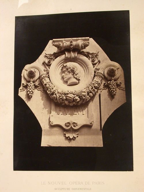
Actions:
Reference number:
PH1979:0162.04:001
Description:
This unbound album comprises 42 plates and title pages and a list of plates (as follows): Le Nouvel Opéra de Paris. Sculpture ornementale Le Nouvel Opéra de Paris. Sculpture ornementale. Chapiteaux, tympans, panneaux, médaillons, masques, cartouches, pilastres, couronnements, clefs, frises, consoles, motifs divers d'ornementation par Charles Garnier, architecte, membre de l'Institut D et Cie, Paris, Librairie Générale de l'Architecture et des Travaux Publics, Ducher et Cie, Éditeurs, 51, rue des Écoles, 51, 1875. Table des Planches 1. - Médaillons - Tympans des arcades du rez-de-chaussée (façade principale). 2. - Cartouche couronnant les pilastres du grand vestibule. 3. - Cartouche servant d'applique sur les piliers du vestibule circulaire. 4. - Tables saillantes. - Galeries latérales du grand escalier. 5. - Table saillante. Pavillon de la descente à couvert. 6. - Table saillante. Vestibules octogones. 7. - Motifs de décoration sur les piliers du vestibule circulaire. 8. - Couronnement des grandes fenêtres. - Façade principale. 9. - Couronnement des portes du grand foyer. 10. - Couronnement desportes à l'extrémité des galeries latérales. 11. - Clef de la grande fenêtre. - Façade postérieure de la scène. 12. - Clef et tympan de la base du vestibule du contrôle. 13. - Clef des arcs dans la coupole du grand escalier. 14. - Clef de la porte. - Pavillon du chef de l'État. 15. - Consoles de chaque côté des oeils-de-boeuf au-dessus des baies de la loggia. 16. - Bas-relief de la partie supérieure de la voûte - vestibule octogone. 17. - Bas-reliefs de l'Attique. - Façade principale. 18. - Pilastres du grand foyer. - Arabesques et chapiteau. 19. - Colonnes du grand foyer. - Base et fut. (sic) 20. - Colonnes de la salle. - Base et fût. 21. - Colonnes des escaliers secondaires. - Fût et chapiteau. 22. - Chapiteau des pilastres du grand escalier. 23. - Chapiteau des colonnes du vestibule. - Pavillon du chef de l'État. 24. - Chapiteau des colonnes du vestibule circulaire. 25. - Chapiteau des colonnes du grand escalier. 26. - Chapiteau des colonnes supportant la 1re volée du grand escalier. 27. - Chapiteau des colonnes des baies de la loggia. - Façade principale. 28. - Chapiteau des colonnes du grand foyer. 29. - Chapiteau des pilastres intérieurs de la loggia. 30. - Chapiteau des colonnes et des pilastres de la salle. 31. - Amortissement des frontons des pavillons. - Façade principale. 32. - Chéneau de la grande coupole de la salle. 33. - Chéneau des façades latérales. 34. - Chéneau de la lanterne de la salle. 35. - Masques du vestibule circulaire. 36. - Masques du vestibule circulaire. 37. - Masques des consoles. - Baies de la loggia (façade principale). 38. - Masques du vestibule du contrôle. 39. - Masques des cheminées des bâtiments de l'administration. 40. - Frise et corniche de la scène. 41. - Frise de l'entablement. - Façade principale. 42. - Clef de voûte. - Galeries latérales. 43. - Clef de voûte. - Descente à couvert. 44. - Clef de voûte. - Galeries latérales. 45. - Clef de voûte. - Galeries latérales.
PH1979:0162.04:001
Description:
This unbound album comprises 42 plates and title pages and a list of plates (as follows): Le Nouvel Opéra de Paris. Sculpture ornementale Le Nouvel Opéra de Paris. Sculpture ornementale. Chapiteaux, tympans, panneaux, médaillons, masques, cartouches, pilastres, couronnements, clefs, frises, consoles, motifs divers d'ornementation par Charles Garnier, architecte, membre de l'Institut D et Cie, Paris, Librairie Générale de l'Architecture et des Travaux Publics, Ducher et Cie, Éditeurs, 51, rue des Écoles, 51, 1875. Table des Planches 1. - Médaillons - Tympans des arcades du rez-de-chaussée (façade principale). 2. - Cartouche couronnant les pilastres du grand vestibule. 3. - Cartouche servant d'applique sur les piliers du vestibule circulaire. 4. - Tables saillantes. - Galeries latérales du grand escalier. 5. - Table saillante. Pavillon de la descente à couvert. 6. - Table saillante. Vestibules octogones. 7. - Motifs de décoration sur les piliers du vestibule circulaire. 8. - Couronnement des grandes fenêtres. - Façade principale. 9. - Couronnement des portes du grand foyer. 10. - Couronnement desportes à l'extrémité des galeries latérales. 11. - Clef de la grande fenêtre. - Façade postérieure de la scène. 12. - Clef et tympan de la base du vestibule du contrôle. 13. - Clef des arcs dans la coupole du grand escalier. 14. - Clef de la porte. - Pavillon du chef de l'État. 15. - Consoles de chaque côté des oeils-de-boeuf au-dessus des baies de la loggia. 16. - Bas-relief de la partie supérieure de la voûte - vestibule octogone. 17. - Bas-reliefs de l'Attique. - Façade principale. 18. - Pilastres du grand foyer. - Arabesques et chapiteau. 19. - Colonnes du grand foyer. - Base et fut. (sic) 20. - Colonnes de la salle. - Base et fût. 21. - Colonnes des escaliers secondaires. - Fût et chapiteau. 22. - Chapiteau des pilastres du grand escalier. 23. - Chapiteau des colonnes du vestibule. - Pavillon du chef de l'État. 24. - Chapiteau des colonnes du vestibule circulaire. 25. - Chapiteau des colonnes du grand escalier. 26. - Chapiteau des colonnes supportant la 1re volée du grand escalier. 27. - Chapiteau des colonnes des baies de la loggia. - Façade principale. 28. - Chapiteau des colonnes du grand foyer. 29. - Chapiteau des pilastres intérieurs de la loggia. 30. - Chapiteau des colonnes et des pilastres de la salle. 31. - Amortissement des frontons des pavillons. - Façade principale. 32. - Chéneau de la grande coupole de la salle. 33. - Chéneau des façades latérales. 34. - Chéneau de la lanterne de la salle. 35. - Masques du vestibule circulaire. 36. - Masques du vestibule circulaire. 37. - Masques des consoles. - Baies de la loggia (façade principale). 38. - Masques du vestibule du contrôle. 39. - Masques des cheminées des bâtiments de l'administration. 40. - Frise et corniche de la scène. 41. - Frise de l'entablement. - Façade principale. 42. - Clef de voûte. - Galeries latérales. 43. - Clef de voûte. - Descente à couvert. 44. - Clef de voûte. - Galeries latérales. 45. - Clef de voûte. - Galeries latérales.
People:
Subject:
architecture, sculpture
architecture, sculpture
Date:
1875 or before
1875 or before
Title:
Médaillons. - Tympans des arcades du rez-de-chaussée (façade principale)
Actions:
PH1979:0162.04:001
Description:
This unbound album comprises 42 plates and title pages and a list of plates (as follows): Le Nouvel Opéra de Paris. Sculpture ornementale Le Nouvel Opéra de Paris. Sculpture ornementale. Chapiteaux, tympans, panneaux, médaillons, masques, cartouches, pilastres, couronnements, clefs, frises, consoles, motifs divers d'ornementation par Charles Garnier, architecte, membre de l'Institut D et Cie, Paris, Librairie Générale de l'Architecture et des Travaux Publics, Ducher et Cie, Éditeurs, 51, rue des Écoles, 51, 1875. Table des Planches 1. - Médaillons - Tympans des arcades du rez-de-chaussée (façade principale). 2. - Cartouche couronnant les pilastres du grand vestibule. 3. - Cartouche servant d'applique sur les piliers du vestibule circulaire. 4. - Tables saillantes. - Galeries latérales du grand escalier. 5. - Table saillante. Pavillon de la descente à couvert. 6. - Table saillante. Vestibules octogones. 7. - Motifs de décoration sur les piliers du vestibule circulaire. 8. - Couronnement des grandes fenêtres. - Façade principale. 9. - Couronnement des portes du grand foyer. 10. - Couronnement desportes à l'extrémité des galeries latérales. 11. - Clef de la grande fenêtre. - Façade postérieure de la scène. 12. - Clef et tympan de la base du vestibule du contrôle. 13. - Clef des arcs dans la coupole du grand escalier. 14. - Clef de la porte. - Pavillon du chef de l'État. 15. - Consoles de chaque côté des oeils-de-boeuf au-dessus des baies de la loggia. 16. - Bas-relief de la partie supérieure de la voûte - vestibule octogone. 17. - Bas-reliefs de l'Attique. - Façade principale. 18. - Pilastres du grand foyer. - Arabesques et chapiteau. 19. - Colonnes du grand foyer. - Base et fut. (sic) 20. - Colonnes de la salle. - Base et fût. 21. - Colonnes des escaliers secondaires. - Fût et chapiteau. 22. - Chapiteau des pilastres du grand escalier. 23. - Chapiteau des colonnes du vestibule. - Pavillon du chef de l'État. 24. - Chapiteau des colonnes du vestibule circulaire. 25. - Chapiteau des colonnes du grand escalier. 26. - Chapiteau des colonnes supportant la 1re volée du grand escalier. 27. - Chapiteau des colonnes des baies de la loggia. - Façade principale. 28. - Chapiteau des colonnes du grand foyer. 29. - Chapiteau des pilastres intérieurs de la loggia. 30. - Chapiteau des colonnes et des pilastres de la salle. 31. - Amortissement des frontons des pavillons. - Façade principale. 32. - Chéneau de la grande coupole de la salle. 33. - Chéneau des façades latérales. 34. - Chéneau de la lanterne de la salle. 35. - Masques du vestibule circulaire. 36. - Masques du vestibule circulaire. 37. - Masques des consoles. - Baies de la loggia (façade principale). 38. - Masques du vestibule du contrôle. 39. - Masques des cheminées des bâtiments de l'administration. 40. - Frise et corniche de la scène. 41. - Frise de l'entablement. - Façade principale. 42. - Clef de voûte. - Galeries latérales. 43. - Clef de voûte. - Descente à couvert. 44. - Clef de voûte. - Galeries latérales. 45. - Clef de voûte. - Galeries latérales.
Médaillons. - Tympans des arcades du rez-de-chaussée (façade principale)
Actions:
PH1979:0162.04:001
Description:
This unbound album comprises 42 plates and title pages and a list of plates (as follows): Le Nouvel Opéra de Paris. Sculpture ornementale Le Nouvel Opéra de Paris. Sculpture ornementale. Chapiteaux, tympans, panneaux, médaillons, masques, cartouches, pilastres, couronnements, clefs, frises, consoles, motifs divers d'ornementation par Charles Garnier, architecte, membre de l'Institut D et Cie, Paris, Librairie Générale de l'Architecture et des Travaux Publics, Ducher et Cie, Éditeurs, 51, rue des Écoles, 51, 1875. Table des Planches 1. - Médaillons - Tympans des arcades du rez-de-chaussée (façade principale). 2. - Cartouche couronnant les pilastres du grand vestibule. 3. - Cartouche servant d'applique sur les piliers du vestibule circulaire. 4. - Tables saillantes. - Galeries latérales du grand escalier. 5. - Table saillante. Pavillon de la descente à couvert. 6. - Table saillante. Vestibules octogones. 7. - Motifs de décoration sur les piliers du vestibule circulaire. 8. - Couronnement des grandes fenêtres. - Façade principale. 9. - Couronnement des portes du grand foyer. 10. - Couronnement desportes à l'extrémité des galeries latérales. 11. - Clef de la grande fenêtre. - Façade postérieure de la scène. 12. - Clef et tympan de la base du vestibule du contrôle. 13. - Clef des arcs dans la coupole du grand escalier. 14. - Clef de la porte. - Pavillon du chef de l'État. 15. - Consoles de chaque côté des oeils-de-boeuf au-dessus des baies de la loggia. 16. - Bas-relief de la partie supérieure de la voûte - vestibule octogone. 17. - Bas-reliefs de l'Attique. - Façade principale. 18. - Pilastres du grand foyer. - Arabesques et chapiteau. 19. - Colonnes du grand foyer. - Base et fut. (sic) 20. - Colonnes de la salle. - Base et fût. 21. - Colonnes des escaliers secondaires. - Fût et chapiteau. 22. - Chapiteau des pilastres du grand escalier. 23. - Chapiteau des colonnes du vestibule. - Pavillon du chef de l'État. 24. - Chapiteau des colonnes du vestibule circulaire. 25. - Chapiteau des colonnes du grand escalier. 26. - Chapiteau des colonnes supportant la 1re volée du grand escalier. 27. - Chapiteau des colonnes des baies de la loggia. - Façade principale. 28. - Chapiteau des colonnes du grand foyer. 29. - Chapiteau des pilastres intérieurs de la loggia. 30. - Chapiteau des colonnes et des pilastres de la salle. 31. - Amortissement des frontons des pavillons. - Façade principale. 32. - Chéneau de la grande coupole de la salle. 33. - Chéneau des façades latérales. 34. - Chéneau de la lanterne de la salle. 35. - Masques du vestibule circulaire. 36. - Masques du vestibule circulaire. 37. - Masques des consoles. - Baies de la loggia (façade principale). 38. - Masques du vestibule du contrôle. 39. - Masques des cheminées des bâtiments de l'administration. 40. - Frise et corniche de la scène. 41. - Frise de l'entablement. - Façade principale. 42. - Clef de voûte. - Galeries latérales. 43. - Clef de voûte. - Descente à couvert. 44. - Clef de voûte. - Galeries latérales. 45. - Clef de voûte. - Galeries latérales.
Form:
photographs
photographs
Date:
1875 or before
1875 or before
People:
Subject:
architecture, sculpture
architecture, sculpture


