


9835 Results
Level of archival description:
Sub-series
Sub-series
Actions:
Reference number:
AP018.S1.1980.PR09.SS1
Description:
This project series documents the design and construction of an office building for Marathon Realty in Toronto at the corner of York and Front Streets from 1980-1983. The office identified the project number as 8009. The project consisted of two nineteen storey towers with stainless steel and glass exteriors connected by a glass atrium on each floor. Owned and commissioned by Marathon Realty, the majority of the building’s space was designed for rental. Due to this, the design was highly modular with no interior walls on most floors. Each floor was approximately 18,000 square feet. The ground floor consisted of a lobby, a bank and a restaurant. At the beginning of this project, the project was named Marathon Realty Office Building, Front and York Streets. Soon after, the office building became known as University Place, which it is often referred to as in these materials. Eventually, the building would become the headquarters of CitiBank and renamed Citigroup Place. The project is recorded through drawings, photographs, textual records and other materials dating from 1980-1987. The majority of the drawings are located within the textual records and show the design of building details. Other drawings include site surveys, design development drawings, presentation drawings, and construction drawings. The photographs show construction progress, tests, models, and the finished project. The textual records contain the project proposal, contracts, client and contractor correspondence, inter-office memos, meeting minutes, financial records, change orders, supplementary instructions, specifications, detail planning, artist’s portfolios for the building’s art competition, site inspection reports, and schedules. File AP018.S1.1980.PR09.004 contains an index to the textual records, which was created by the office. The CCA also holds materials for a subproject under this project series, which document the installation of signs to the top of the building after the building's construction (AP018.S1.1980.PR09.SS1). Subproject materials are viewed separately from the project due to the different project numbers originally assigned by the office.
AP018.S1.1980.PR09.SS1
Description:
This project series documents the design and construction of an office building for Marathon Realty in Toronto at the corner of York and Front Streets from 1980-1983. The office identified the project number as 8009. The project consisted of two nineteen storey towers with stainless steel and glass exteriors connected by a glass atrium on each floor. Owned and commissioned by Marathon Realty, the majority of the building’s space was designed for rental. Due to this, the design was highly modular with no interior walls on most floors. Each floor was approximately 18,000 square feet. The ground floor consisted of a lobby, a bank and a restaurant. At the beginning of this project, the project was named Marathon Realty Office Building, Front and York Streets. Soon after, the office building became known as University Place, which it is often referred to as in these materials. Eventually, the building would become the headquarters of CitiBank and renamed Citigroup Place. The project is recorded through drawings, photographs, textual records and other materials dating from 1980-1987. The majority of the drawings are located within the textual records and show the design of building details. Other drawings include site surveys, design development drawings, presentation drawings, and construction drawings. The photographs show construction progress, tests, models, and the finished project. The textual records contain the project proposal, contracts, client and contractor correspondence, inter-office memos, meeting minutes, financial records, change orders, supplementary instructions, specifications, detail planning, artist’s portfolios for the building’s art competition, site inspection reports, and schedules. File AP018.S1.1980.PR09.004 contains an index to the textual records, which was created by the office. The CCA also holds materials for a subproject under this project series, which document the installation of signs to the top of the building after the building's construction (AP018.S1.1980.PR09.SS1). Subproject materials are viewed separately from the project due to the different project numbers originally assigned by the office.
People:
Date:
1980-1987
1980-1987
Title:
University Place Building, Front and York Streets, Toronto (1980-1987)
Actions:
AP018.S1.1980.PR09.SS1
Description:
This project series documents the design and construction of an office building for Marathon Realty in Toronto at the corner of York and Front Streets from 1980-1983. The office identified the project number as 8009. The project consisted of two nineteen storey towers with stainless steel and glass exteriors connected by a glass atrium on each floor. Owned and commissioned by Marathon Realty, the majority of the building’s space was designed for rental. Due to this, the design was highly modular with no interior walls on most floors. Each floor was approximately 18,000 square feet. The ground floor consisted of a lobby, a bank and a restaurant. At the beginning of this project, the project was named Marathon Realty Office Building, Front and York Streets. Soon after, the office building became known as University Place, which it is often referred to as in these materials. Eventually, the building would become the headquarters of CitiBank and renamed Citigroup Place. The project is recorded through drawings, photographs, textual records and other materials dating from 1980-1987. The majority of the drawings are located within the textual records and show the design of building details. Other drawings include site surveys, design development drawings, presentation drawings, and construction drawings. The photographs show construction progress, tests, models, and the finished project. The textual records contain the project proposal, contracts, client and contractor correspondence, inter-office memos, meeting minutes, financial records, change orders, supplementary instructions, specifications, detail planning, artist’s portfolios for the building’s art competition, site inspection reports, and schedules. File AP018.S1.1980.PR09.004 contains an index to the textual records, which was created by the office. The CCA also holds materials for a subproject under this project series, which document the installation of signs to the top of the building after the building's construction (AP018.S1.1980.PR09.SS1). Subproject materials are viewed separately from the project due to the different project numbers originally assigned by the office.
University Place Building, Front and York Streets, Toronto (1980-1987)
Actions:
AP018.S1.1980.PR09.SS1
Description:
This project series documents the design and construction of an office building for Marathon Realty in Toronto at the corner of York and Front Streets from 1980-1983. The office identified the project number as 8009. The project consisted of two nineteen storey towers with stainless steel and glass exteriors connected by a glass atrium on each floor. Owned and commissioned by Marathon Realty, the majority of the building’s space was designed for rental. Due to this, the design was highly modular with no interior walls on most floors. Each floor was approximately 18,000 square feet. The ground floor consisted of a lobby, a bank and a restaurant. At the beginning of this project, the project was named Marathon Realty Office Building, Front and York Streets. Soon after, the office building became known as University Place, which it is often referred to as in these materials. Eventually, the building would become the headquarters of CitiBank and renamed Citigroup Place. The project is recorded through drawings, photographs, textual records and other materials dating from 1980-1987. The majority of the drawings are located within the textual records and show the design of building details. Other drawings include site surveys, design development drawings, presentation drawings, and construction drawings. The photographs show construction progress, tests, models, and the finished project. The textual records contain the project proposal, contracts, client and contractor correspondence, inter-office memos, meeting minutes, financial records, change orders, supplementary instructions, specifications, detail planning, artist’s portfolios for the building’s art competition, site inspection reports, and schedules. File AP018.S1.1980.PR09.004 contains an index to the textual records, which was created by the office. The CCA also holds materials for a subproject under this project series, which document the installation of signs to the top of the building after the building's construction (AP018.S1.1980.PR09.SS1). Subproject materials are viewed separately from the project due to the different project numbers originally assigned by the office.
Level of archival description:
Project
Project
Date:
1980-1987
1980-1987
People:
Form:
archives
Level of archival description:
Fonds
archives
Level of archival description:
Fonds
Title:
Shoei Yoh fonds
Shoei Yoh fonds
Reference number:
AP166
Synopsis:
The Shoei Yoh fonds (1976-2014, predominant 1990-1996) documents a selection of works by the Japanese architect and designer Shoei Yoh and the firm Shoei Yoh + Architects. The selection is comprised of two projects that were featured in the CCA exhibition Archaeology of the Digital (May 7-October 27, 2013)—the Galaxy Toyama Gymnasium and the unbuilt Odawara Municipal Sports Complex --and five other projects.The fonds also includes some published material by and about Shoei Yoh.
AP166
Synopsis:
The Shoei Yoh fonds (1976-2014, predominant 1990-1996) documents a selection of works by the Japanese architect and designer Shoei Yoh and the firm Shoei Yoh + Architects. The selection is comprised of two projects that were featured in the CCA exhibition Archaeology of the Digital (May 7-October 27, 2013)—the Galaxy Toyama Gymnasium and the unbuilt Odawara Municipal Sports Complex --and five other projects.The fonds also includes some published material by and about Shoei Yoh.
People:
Date:
1976-2014, predominant 1990-1996
1976-2014, predominant 1990-1996
Title:
Shoei Yoh fonds
Actions:
AP166
Synopsis:
The Shoei Yoh fonds (1976-2014, predominant 1990-1996) documents a selection of works by the Japanese architect and designer Shoei Yoh and the firm Shoei Yoh + Architects. The selection is comprised of two projects that were featured in the CCA exhibition Archaeology of the Digital (May 7-October 27, 2013)—the Galaxy Toyama Gymnasium and the unbuilt Odawara Municipal Sports Complex --and five other projects.The fonds also includes some published material by and about Shoei Yoh.
Shoei Yoh fonds
Actions:
AP166
Synopsis:
The Shoei Yoh fonds (1976-2014, predominant 1990-1996) documents a selection of works by the Japanese architect and designer Shoei Yoh and the firm Shoei Yoh + Architects. The selection is comprised of two projects that were featured in the CCA exhibition Archaeology of the Digital (May 7-October 27, 2013)—the Galaxy Toyama Gymnasium and the unbuilt Odawara Municipal Sports Complex --and five other projects.The fonds also includes some published material by and about Shoei Yoh.
Form:
archives
Level of archival description:
Fonds
archives
Level of archival description:
Fonds
Date:
1976-2014, predominant 1990-1996
1976-2014, predominant 1990-1996
People:
Form:
archives
Level of archival description:
Fonds
archives
Level of archival description:
Fonds
Actions:
Reference number:
AP002
Synopsis:
The Ludger and Paul M. Lemieux fonds, 1897-1966, documents the built projects of Québec architectural firm, Ludger & Paul M. Lemieux. The 500 projects that are represented in this fonds are divided by the architectural works of Macduff & Lemieux (1897-1917), Ludger Lemieux (1910-1950), Ludger & Paul M. Lemieux (1929-1951), and Paul M. Lemieux (1934-1966). Materials in this fonds consist of 4988 drawings (including reprographic prints), 320 photographic materials and 5 l.m. of textual records.
AP002
Synopsis:
The Ludger and Paul M. Lemieux fonds, 1897-1966, documents the built projects of Québec architectural firm, Ludger & Paul M. Lemieux. The 500 projects that are represented in this fonds are divided by the architectural works of Macduff & Lemieux (1897-1917), Ludger Lemieux (1910-1950), Ludger & Paul M. Lemieux (1929-1951), and Paul M. Lemieux (1934-1966). Materials in this fonds consist of 4988 drawings (including reprographic prints), 320 photographic materials and 5 l.m. of textual records.
People:
Date:
1897-1966
1897-1966
Title:
Ludger and Paul M. Lemieux fonds
Actions:
AP002
Synopsis:
The Ludger and Paul M. Lemieux fonds, 1897-1966, documents the built projects of Québec architectural firm, Ludger & Paul M. Lemieux. The 500 projects that are represented in this fonds are divided by the architectural works of Macduff & Lemieux (1897-1917), Ludger Lemieux (1910-1950), Ludger & Paul M. Lemieux (1929-1951), and Paul M. Lemieux (1934-1966). Materials in this fonds consist of 4988 drawings (including reprographic prints), 320 photographic materials and 5 l.m. of textual records.
Ludger and Paul M. Lemieux fonds
Actions:
AP002
Synopsis:
The Ludger and Paul M. Lemieux fonds, 1897-1966, documents the built projects of Québec architectural firm, Ludger & Paul M. Lemieux. The 500 projects that are represented in this fonds are divided by the architectural works of Macduff & Lemieux (1897-1917), Ludger Lemieux (1910-1950), Ludger & Paul M. Lemieux (1929-1951), and Paul M. Lemieux (1934-1966). Materials in this fonds consist of 4988 drawings (including reprographic prints), 320 photographic materials and 5 l.m. of textual records.
Form:
archives
Level of archival description:
Fonds
archives
Level of archival description:
Fonds
Date:
1897-1966
1897-1966
People:
Form:
drawings, works of art
drawings, works of art
Actions:
Reference number:
DR1974:0002:014:001-104
Description:
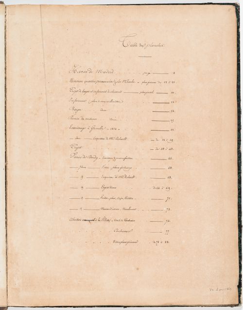
- This album contains drawings by Hubert and Charles Rohault de Fleury for six projects related to horses, with some pertaining to larger issues of urban development. The drawings range from design development drawings to highly finished renderings - mostly plans, elevations and sections. The proposed projects are in a pared-down classical style typical of the Rohault de Fleury's utilitarian structures. The projects include a stud-farm, Haras de Madrid, Bois de Boulogne (1819); a horse auction house (bazaar) and infirmary, Clos St. Charles, nouveau quartier Poissonnière, including studies for the development of the quartier (1823-1825); Clos d'équarrissage, fôret de Bondy (probably 1825-1827); and three projects for horse slaughterhouses: Plaine de Grenelle (1824), an unnamed project (probably between 1825 and 1827), and La Villette (1835-1836). Hubert's project for a stud-farm on the site of the old Château de Madrid consists mostly of highly finished plans, elevations, and sections for the stables (DR1974:0002:014:001 - DR1974:0002:014:013). Hubert's project for a horse auction house (bazaar) and infirmary for the Clos St. Charles area is apparently part of a larger project to develop the nouveau quartier Poissonnière (DR1974:0002:014:014 - DR1974:0002:014:029). The numerous site plans show the horse auction house (bazaar) and infirmary, proposed roads, and properties to be purchased and sold. Included is a property lots plan for the quartier (DR1974:0002:014:014). Hubert's Clos d'équarrissage is the most extensive project in the album. Forty-three finished drawings - including construction drawings and plans showing variant configurations for the disposition of buildings - depict a slaughterhouse, a factory for the preservation of muscles, buildings for the preservation and processing of offal, and workers' housing (DR1974:0002:014:051 - DR1974:0002:014:088, DR1974:0002:014:091 - DR1974:0002:014:093, DR1974:0002:014:095 and DR1974:002:014:096). Hubert's drawings for a horse slaughterhouse, Plaine de Grenelle, range from detailed design development drawings to highly finished site plans (DR1974:0002:014:030 - DR1974:0002:014:048) and a bird's-eye view of the slaughterhouse (DR1974:0002:014:033). The drawings for an unidentified slaughterhouse are possibly for this project (DR1974:0002:014:049 - DR1974:0002:014:051). Charles's project for a slaughterhouse at La Villette consists of variant site plans (DR1974:0002:014:089 - DR1974:00002:014:090, DR1974:0002:014:095, DR1974:0002:014:104).
DR1974:0002:014:001-104
Description:
- This album contains drawings by Hubert and Charles Rohault de Fleury for six projects related to horses, with some pertaining to larger issues of urban development. The drawings range from design development drawings to highly finished renderings - mostly plans, elevations and sections. The proposed projects are in a pared-down classical style typical of the Rohault de Fleury's utilitarian structures. The projects include a stud-farm, Haras de Madrid, Bois de Boulogne (1819); a horse auction house (bazaar) and infirmary, Clos St. Charles, nouveau quartier Poissonnière, including studies for the development of the quartier (1823-1825); Clos d'équarrissage, fôret de Bondy (probably 1825-1827); and three projects for horse slaughterhouses: Plaine de Grenelle (1824), an unnamed project (probably between 1825 and 1827), and La Villette (1835-1836). Hubert's project for a stud-farm on the site of the old Château de Madrid consists mostly of highly finished plans, elevations, and sections for the stables (DR1974:0002:014:001 - DR1974:0002:014:013). Hubert's project for a horse auction house (bazaar) and infirmary for the Clos St. Charles area is apparently part of a larger project to develop the nouveau quartier Poissonnière (DR1974:0002:014:014 - DR1974:0002:014:029). The numerous site plans show the horse auction house (bazaar) and infirmary, proposed roads, and properties to be purchased and sold. Included is a property lots plan for the quartier (DR1974:0002:014:014). Hubert's Clos d'équarrissage is the most extensive project in the album. Forty-three finished drawings - including construction drawings and plans showing variant configurations for the disposition of buildings - depict a slaughterhouse, a factory for the preservation of muscles, buildings for the preservation and processing of offal, and workers' housing (DR1974:0002:014:051 - DR1974:0002:014:088, DR1974:0002:014:091 - DR1974:0002:014:093, DR1974:0002:014:095 and DR1974:002:014:096). Hubert's drawings for a horse slaughterhouse, Plaine de Grenelle, range from detailed design development drawings to highly finished site plans (DR1974:0002:014:030 - DR1974:0002:014:048) and a bird's-eye view of the slaughterhouse (DR1974:0002:014:033). The drawings for an unidentified slaughterhouse are possibly for this project (DR1974:0002:014:049 - DR1974:0002:014:051). Charles's project for a slaughterhouse at La Villette consists of variant site plans (DR1974:0002:014:089 - DR1974:00002:014:090, DR1974:0002:014:095, DR1974:0002:014:104).
People:
Subject:
architecture, urban planning
architecture, urban planning
Date:
1835-1836, printed 1819-1827 ?
1835-1836, printed 1819-1827 ?
Title:
Album of drawings for six projects related to horses: a stud-farm, an auction house and infirmary, and slaughterhouses, France
Actions:
DR1974:0002:014:001-104
Description:
- This album contains drawings by Hubert and Charles Rohault de Fleury for six projects related to horses, with some pertaining to larger issues of urban development. The drawings range from design development drawings to highly finished renderings - mostly plans, elevations and sections. The proposed projects are in a pared-down classical style typical of the Rohault de Fleury's utilitarian structures. The projects include a stud-farm, Haras de Madrid, Bois de Boulogne (1819); a horse auction house (bazaar) and infirmary, Clos St. Charles, nouveau quartier Poissonnière, including studies for the development of the quartier (1823-1825); Clos d'équarrissage, fôret de Bondy (probably 1825-1827); and three projects for horse slaughterhouses: Plaine de Grenelle (1824), an unnamed project (probably between 1825 and 1827), and La Villette (1835-1836). Hubert's project for a stud-farm on the site of the old Château de Madrid consists mostly of highly finished plans, elevations, and sections for the stables (DR1974:0002:014:001 - DR1974:0002:014:013). Hubert's project for a horse auction house (bazaar) and infirmary for the Clos St. Charles area is apparently part of a larger project to develop the nouveau quartier Poissonnière (DR1974:0002:014:014 - DR1974:0002:014:029). The numerous site plans show the horse auction house (bazaar) and infirmary, proposed roads, and properties to be purchased and sold. Included is a property lots plan for the quartier (DR1974:0002:014:014). Hubert's Clos d'équarrissage is the most extensive project in the album. Forty-three finished drawings - including construction drawings and plans showing variant configurations for the disposition of buildings - depict a slaughterhouse, a factory for the preservation of muscles, buildings for the preservation and processing of offal, and workers' housing (DR1974:0002:014:051 - DR1974:0002:014:088, DR1974:0002:014:091 - DR1974:0002:014:093, DR1974:0002:014:095 and DR1974:002:014:096). Hubert's drawings for a horse slaughterhouse, Plaine de Grenelle, range from detailed design development drawings to highly finished site plans (DR1974:0002:014:030 - DR1974:0002:014:048) and a bird's-eye view of the slaughterhouse (DR1974:0002:014:033). The drawings for an unidentified slaughterhouse are possibly for this project (DR1974:0002:014:049 - DR1974:0002:014:051). Charles's project for a slaughterhouse at La Villette consists of variant site plans (DR1974:0002:014:089 - DR1974:00002:014:090, DR1974:0002:014:095, DR1974:0002:014:104).
Album of drawings for six projects related to horses: a stud-farm, an auction house and infirmary, and slaughterhouses, France
Actions:
DR1974:0002:014:001-104
Description:
- This album contains drawings by Hubert and Charles Rohault de Fleury for six projects related to horses, with some pertaining to larger issues of urban development. The drawings range from design development drawings to highly finished renderings - mostly plans, elevations and sections. The proposed projects are in a pared-down classical style typical of the Rohault de Fleury's utilitarian structures. The projects include a stud-farm, Haras de Madrid, Bois de Boulogne (1819); a horse auction house (bazaar) and infirmary, Clos St. Charles, nouveau quartier Poissonnière, including studies for the development of the quartier (1823-1825); Clos d'équarrissage, fôret de Bondy (probably 1825-1827); and three projects for horse slaughterhouses: Plaine de Grenelle (1824), an unnamed project (probably between 1825 and 1827), and La Villette (1835-1836). Hubert's project for a stud-farm on the site of the old Château de Madrid consists mostly of highly finished plans, elevations, and sections for the stables (DR1974:0002:014:001 - DR1974:0002:014:013). Hubert's project for a horse auction house (bazaar) and infirmary for the Clos St. Charles area is apparently part of a larger project to develop the nouveau quartier Poissonnière (DR1974:0002:014:014 - DR1974:0002:014:029). The numerous site plans show the horse auction house (bazaar) and infirmary, proposed roads, and properties to be purchased and sold. Included is a property lots plan for the quartier (DR1974:0002:014:014). Hubert's Clos d'équarrissage is the most extensive project in the album. Forty-three finished drawings - including construction drawings and plans showing variant configurations for the disposition of buildings - depict a slaughterhouse, a factory for the preservation of muscles, buildings for the preservation and processing of offal, and workers' housing (DR1974:0002:014:051 - DR1974:0002:014:088, DR1974:0002:014:091 - DR1974:0002:014:093, DR1974:0002:014:095 and DR1974:002:014:096). Hubert's drawings for a horse slaughterhouse, Plaine de Grenelle, range from detailed design development drawings to highly finished site plans (DR1974:0002:014:030 - DR1974:0002:014:048) and a bird's-eye view of the slaughterhouse (DR1974:0002:014:033). The drawings for an unidentified slaughterhouse are possibly for this project (DR1974:0002:014:049 - DR1974:0002:014:051). Charles's project for a slaughterhouse at La Villette consists of variant site plans (DR1974:0002:014:089 - DR1974:00002:014:090, DR1974:0002:014:095, DR1974:0002:014:104).
Form:
drawings, works of art
drawings, works of art
Date:
1835-1836, printed 1819-1827 ?
1835-1836, printed 1819-1827 ?
People:
Subject:
architecture, urban planning
architecture, urban planning
Form:
drawings, textual records, born digital, photographs
drawings, textual records, born digital, photographs
Actions:
Reference number:
AP181.S1.019
Description:
Original directory name: "25_TRIAS-Aussenbrücke". File content shows the design and construction planning for a pedestrian bridge connecting BMW Welt to the BMW Museum. Records include plans, drawings, research material, presentations, approval planning, building specification, list of plans, final handover of the arch bridge, etc. The bulk of records are CAD drawings and 3D models of the design development and planning. The drawings are organized by type of plan: site plan, sections, axonometric views, etc. As for 3D models, they are organized mostly by file format, and then by date. The "3D" sub-directory also contains more than 1500 screenshots saved as JPEG. Additional records include site photographs, digitized sketches, visual research material, presentations of the concept, bridge structure technical descriptions, 2D and 3D technical drawings (in PDF, CAD, JPG, and Illustrator formats), renderings, project planning charts, and plan lists. Most common file formats: JPEG File Interchange Format, AutoCAD Drawing, 3DM, Exchangeable Image File Format (Compressed), Maya Binary File Format
AP181.S1.019
Description:
Original directory name: "25_TRIAS-Aussenbrücke". File content shows the design and construction planning for a pedestrian bridge connecting BMW Welt to the BMW Museum. Records include plans, drawings, research material, presentations, approval planning, building specification, list of plans, final handover of the arch bridge, etc. The bulk of records are CAD drawings and 3D models of the design development and planning. The drawings are organized by type of plan: site plan, sections, axonometric views, etc. As for 3D models, they are organized mostly by file format, and then by date. The "3D" sub-directory also contains more than 1500 screenshots saved as JPEG. Additional records include site photographs, digitized sketches, visual research material, presentations of the concept, bridge structure technical descriptions, 2D and 3D technical drawings (in PDF, CAD, JPG, and Illustrator formats), renderings, project planning charts, and plan lists. Most common file formats: JPEG File Interchange Format, AutoCAD Drawing, 3DM, Exchangeable Image File Format (Compressed), Maya Binary File Format
People:
Date:
2002-2007
2002-2007
Title:
Design and construction planning of bridge to BMW Museum, BMW Welt, Munich
Actions:
AP181.S1.019
Description:
Original directory name: "25_TRIAS-Aussenbrücke". File content shows the design and construction planning for a pedestrian bridge connecting BMW Welt to the BMW Museum. Records include plans, drawings, research material, presentations, approval planning, building specification, list of plans, final handover of the arch bridge, etc. The bulk of records are CAD drawings and 3D models of the design development and planning. The drawings are organized by type of plan: site plan, sections, axonometric views, etc. As for 3D models, they are organized mostly by file format, and then by date. The "3D" sub-directory also contains more than 1500 screenshots saved as JPEG. Additional records include site photographs, digitized sketches, visual research material, presentations of the concept, bridge structure technical descriptions, 2D and 3D technical drawings (in PDF, CAD, JPG, and Illustrator formats), renderings, project planning charts, and plan lists. Most common file formats: JPEG File Interchange Format, AutoCAD Drawing, 3DM, Exchangeable Image File Format (Compressed), Maya Binary File Format
Design and construction planning of bridge to BMW Museum, BMW Welt, Munich
Actions:
AP181.S1.019
Description:
Original directory name: "25_TRIAS-Aussenbrücke". File content shows the design and construction planning for a pedestrian bridge connecting BMW Welt to the BMW Museum. Records include plans, drawings, research material, presentations, approval planning, building specification, list of plans, final handover of the arch bridge, etc. The bulk of records are CAD drawings and 3D models of the design development and planning. The drawings are organized by type of plan: site plan, sections, axonometric views, etc. As for 3D models, they are organized mostly by file format, and then by date. The "3D" sub-directory also contains more than 1500 screenshots saved as JPEG. Additional records include site photographs, digitized sketches, visual research material, presentations of the concept, bridge structure technical descriptions, 2D and 3D technical drawings (in PDF, CAD, JPG, and Illustrator formats), renderings, project planning charts, and plan lists. Most common file formats: JPEG File Interchange Format, AutoCAD Drawing, 3DM, Exchangeable Image File Format (Compressed), Maya Binary File Format
Form:
drawings, textual records, born digital, photographs
drawings, textual records, born digital, photographs
Date:
2002-2007
2002-2007
People:
Form:
drawings, works of art
drawings, works of art

Actions:
Reference number:
DR1974:0002:027:001-027
Description:
- This album consists of 23 presentation drawings and transfer lithographs for an 1859-1860 project for an opera house for the Théâtre impérial de l'opéra. Three drawings and one engraving for the project which are included in the album, are not listed in the table of contents (DR1974:0002:027:005, DR1974:0002:027:006, DR1974:0002:027:021, DR1974:0002:027:027). Site plans DR1974:0002:027:002 and DR1974:0002:027:003 show the opera house on an irregular polygonal site just off boulevard des Capucines, enclosed by rues Neuve Mogador, Neuve des Mathurins, du Chemin de fer de l'Ouest (proposed), de l'Opéra (proposed), and place de l'Opéra (proposed). The principal façade is two storeys high and five bays wide. Serliana arches are supported and separated by Doric columns below and by Ionic columns above (DR1974:0002:027:004, DR1974:0002:027:006, and DR1974:0002:027:007). Iron roof trusses are visible in cross section DR1974:0002:027:024. The auditorium is a modified horseshoe shape, squarish in plan (DR1974:0002:027:012 - DR1974:0002:027:014). A cross section through the auditorium shows the stage curtain with a trompe-l'oeil view of the opera's proposed principal façade.
DR1974:0002:027:001-027
Description:
- This album consists of 23 presentation drawings and transfer lithographs for an 1859-1860 project for an opera house for the Théâtre impérial de l'opéra. Three drawings and one engraving for the project which are included in the album, are not listed in the table of contents (DR1974:0002:027:005, DR1974:0002:027:006, DR1974:0002:027:021, DR1974:0002:027:027). Site plans DR1974:0002:027:002 and DR1974:0002:027:003 show the opera house on an irregular polygonal site just off boulevard des Capucines, enclosed by rues Neuve Mogador, Neuve des Mathurins, du Chemin de fer de l'Ouest (proposed), de l'Opéra (proposed), and place de l'Opéra (proposed). The principal façade is two storeys high and five bays wide. Serliana arches are supported and separated by Doric columns below and by Ionic columns above (DR1974:0002:027:004, DR1974:0002:027:006, and DR1974:0002:027:007). Iron roof trusses are visible in cross section DR1974:0002:027:024. The auditorium is a modified horseshoe shape, squarish in plan (DR1974:0002:027:012 - DR1974:0002:027:014). A cross section through the auditorium shows the stage curtain with a trompe-l'oeil view of the opera's proposed principal façade.
People:
Subject:
architecture, interior design, urban planning
architecture, interior design, urban planning
Date:
printed 1857-1860
printed 1857-1860
Title:
Album of drawings and prints for an opera house for the Théâtre impérial de l'opéra, Paris
Actions:
DR1974:0002:027:001-027
Description:
- This album consists of 23 presentation drawings and transfer lithographs for an 1859-1860 project for an opera house for the Théâtre impérial de l'opéra. Three drawings and one engraving for the project which are included in the album, are not listed in the table of contents (DR1974:0002:027:005, DR1974:0002:027:006, DR1974:0002:027:021, DR1974:0002:027:027). Site plans DR1974:0002:027:002 and DR1974:0002:027:003 show the opera house on an irregular polygonal site just off boulevard des Capucines, enclosed by rues Neuve Mogador, Neuve des Mathurins, du Chemin de fer de l'Ouest (proposed), de l'Opéra (proposed), and place de l'Opéra (proposed). The principal façade is two storeys high and five bays wide. Serliana arches are supported and separated by Doric columns below and by Ionic columns above (DR1974:0002:027:004, DR1974:0002:027:006, and DR1974:0002:027:007). Iron roof trusses are visible in cross section DR1974:0002:027:024. The auditorium is a modified horseshoe shape, squarish in plan (DR1974:0002:027:012 - DR1974:0002:027:014). A cross section through the auditorium shows the stage curtain with a trompe-l'oeil view of the opera's proposed principal façade.
Album of drawings and prints for an opera house for the Théâtre impérial de l'opéra, Paris
Actions:
DR1974:0002:027:001-027
Description:
- This album consists of 23 presentation drawings and transfer lithographs for an 1859-1860 project for an opera house for the Théâtre impérial de l'opéra. Three drawings and one engraving for the project which are included in the album, are not listed in the table of contents (DR1974:0002:027:005, DR1974:0002:027:006, DR1974:0002:027:021, DR1974:0002:027:027). Site plans DR1974:0002:027:002 and DR1974:0002:027:003 show the opera house on an irregular polygonal site just off boulevard des Capucines, enclosed by rues Neuve Mogador, Neuve des Mathurins, du Chemin de fer de l'Ouest (proposed), de l'Opéra (proposed), and place de l'Opéra (proposed). The principal façade is two storeys high and five bays wide. Serliana arches are supported and separated by Doric columns below and by Ionic columns above (DR1974:0002:027:004, DR1974:0002:027:006, and DR1974:0002:027:007). Iron roof trusses are visible in cross section DR1974:0002:027:024. The auditorium is a modified horseshoe shape, squarish in plan (DR1974:0002:027:012 - DR1974:0002:027:014). A cross section through the auditorium shows the stage curtain with a trompe-l'oeil view of the opera's proposed principal façade.
Form:
drawings, works of art
drawings, works of art
Date:
printed 1857-1860
printed 1857-1860
People:
Subject:
architecture, interior design, urban planning
architecture, interior design, urban planning
Form:
drawings, works of art
drawings, works of art
Actions:
Reference number:
DR1974:0002:019:001-023
Description:
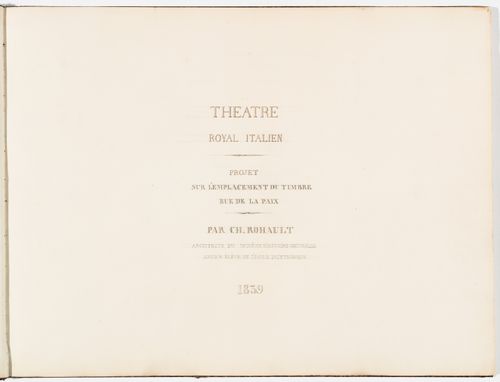
- This album contains elevations, plans, and sections for Rohault de Fleury's unexecuted project to construct a new opera house for the Théâtre Royal Italien on the site of the Hôtel du Timbre and the Ministère des Affaires Étrangères. The finished nature of the drawings, and their cohesive representation, suggests that they are presentation drawings for a prospective client(s). The unbound engraving and transfer lithograph (DR1974:0002:019:001 and DR1974:0002:019:002) relate directly to the subject matter of the album, however, they are probably later additions as they do not appear in the table of contents.
DR1974:0002:019:001-023
Description:
- This album contains elevations, plans, and sections for Rohault de Fleury's unexecuted project to construct a new opera house for the Théâtre Royal Italien on the site of the Hôtel du Timbre and the Ministère des Affaires Étrangères. The finished nature of the drawings, and their cohesive representation, suggests that they are presentation drawings for a prospective client(s). The unbound engraving and transfer lithograph (DR1974:0002:019:001 and DR1974:0002:019:002) relate directly to the subject matter of the album, however, they are probably later additions as they do not appear in the table of contents.
People:
Subject:
architecture
architecture
Date:
drawings executed in 1839, prints executed in 1838
drawings executed in 1839, prints executed in 1838
Title:
Album of plans, elevations and sections for the Théâtre-Italien, rue de la Paix, Paris
Actions:
DR1974:0002:019:001-023
Description:
- This album contains elevations, plans, and sections for Rohault de Fleury's unexecuted project to construct a new opera house for the Théâtre Royal Italien on the site of the Hôtel du Timbre and the Ministère des Affaires Étrangères. The finished nature of the drawings, and their cohesive representation, suggests that they are presentation drawings for a prospective client(s). The unbound engraving and transfer lithograph (DR1974:0002:019:001 and DR1974:0002:019:002) relate directly to the subject matter of the album, however, they are probably later additions as they do not appear in the table of contents.
Album of plans, elevations and sections for the Théâtre-Italien, rue de la Paix, Paris
Actions:
DR1974:0002:019:001-023
Description:
- This album contains elevations, plans, and sections for Rohault de Fleury's unexecuted project to construct a new opera house for the Théâtre Royal Italien on the site of the Hôtel du Timbre and the Ministère des Affaires Étrangères. The finished nature of the drawings, and their cohesive representation, suggests that they are presentation drawings for a prospective client(s). The unbound engraving and transfer lithograph (DR1974:0002:019:001 and DR1974:0002:019:002) relate directly to the subject matter of the album, however, they are probably later additions as they do not appear in the table of contents.
Form:
drawings, works of art
drawings, works of art
Date:
drawings executed in 1839, prints executed in 1838
drawings executed in 1839, prints executed in 1838
People:
Subject:
architecture
architecture
Form:
drawings
drawings
Actions:
Reference number:
DR1984:0009
Description:
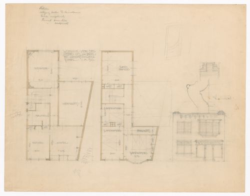
- Drawing DR1984:0009 for a shop and house for G.S. van Bakel (Heemstede) shows a design for an L-shaped plan, which differs from the rectangular plan of later blueprints DR1984:0479 - DR1984:0482. A cornice detail and revision [?] to the elevation appear at the center right of drawing DR1984:0009. Blueprint DR1984:0482 has a key at the lower left which indicates that cross-hatched lines on the site plan indicate existing built areas (bestaande gebouwen), while single hatched lines indicate proposed areas of construction for the house and surroundings (te bouwen huis enz.).
DR1984:0009
Description:
- Drawing DR1984:0009 for a shop and house for G.S. van Bakel (Heemstede) shows a design for an L-shaped plan, which differs from the rectangular plan of later blueprints DR1984:0479 - DR1984:0482. A cornice detail and revision [?] to the elevation appear at the center right of drawing DR1984:0009. Blueprint DR1984:0482 has a key at the lower left which indicates that cross-hatched lines on the site plan indicate existing built areas (bestaande gebouwen), while single hatched lines indicate proposed areas of construction for the house and surroundings (te bouwen huis enz.).
People:
Subject:
architecture
architecture
Date:
1914
1914
Title:
Ground and first floor plans and principal elevation for a house and shop with an L-shaped plan for Mr. G.S. van Bakel, Heemstede, Netherlands
Actions:
DR1984:0009
Description:
- Drawing DR1984:0009 for a shop and house for G.S. van Bakel (Heemstede) shows a design for an L-shaped plan, which differs from the rectangular plan of later blueprints DR1984:0479 - DR1984:0482. A cornice detail and revision [?] to the elevation appear at the center right of drawing DR1984:0009. Blueprint DR1984:0482 has a key at the lower left which indicates that cross-hatched lines on the site plan indicate existing built areas (bestaande gebouwen), while single hatched lines indicate proposed areas of construction for the house and surroundings (te bouwen huis enz.).
Ground and first floor plans and principal elevation for a house and shop with an L-shaped plan for Mr. G.S. van Bakel, Heemstede, Netherlands
Actions:
DR1984:0009
Description:
- Drawing DR1984:0009 for a shop and house for G.S. van Bakel (Heemstede) shows a design for an L-shaped plan, which differs from the rectangular plan of later blueprints DR1984:0479 - DR1984:0482. A cornice detail and revision [?] to the elevation appear at the center right of drawing DR1984:0009. Blueprint DR1984:0482 has a key at the lower left which indicates that cross-hatched lines on the site plan indicate existing built areas (bestaande gebouwen), while single hatched lines indicate proposed areas of construction for the house and surroundings (te bouwen huis enz.).
Form:
drawings
drawings
Date:
1914
1914
People:
Subject:
architecture
architecture
Form:
drawings
drawings
Actions:
Reference number:
DR1984:0479
Description:
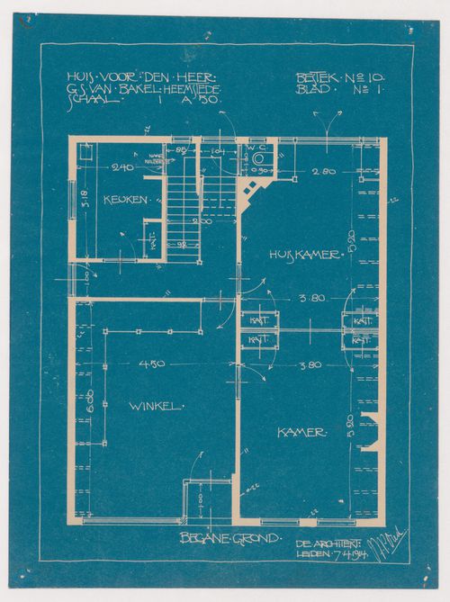
- Drawing DR1984:0009 for a shop and house for G.S. van Bakel (Heemstede) shows a design for an L-shaped plan, which differs from the rectangular plan of later blueprints DR1984:0479 - DR1984:0482. A cornice detail and revisions [?] to the elevation appear at the center right of drawing DR1984:0009. Blueprint DR1984:0482 has a key at the lower left which indicates that cross-hatched lines on the site plan indicate existing built areas (bestaande gebouwen), while single hatched lines indicate proposed areas of construction for the house and surroundings (te bouwen huis enz.).
DR1984:0479
Description:
- Drawing DR1984:0009 for a shop and house for G.S. van Bakel (Heemstede) shows a design for an L-shaped plan, which differs from the rectangular plan of later blueprints DR1984:0479 - DR1984:0482. A cornice detail and revisions [?] to the elevation appear at the center right of drawing DR1984:0009. Blueprint DR1984:0482 has a key at the lower left which indicates that cross-hatched lines on the site plan indicate existing built areas (bestaande gebouwen), while single hatched lines indicate proposed areas of construction for the house and surroundings (te bouwen huis enz.).
People:
Subject:
architecture
architecture
Date:
printed 1914
printed 1914
Title:
Ground floor plan for a house and shop with a rectangular plan for Mr. G.S. van Bakel, Heemstede, Netherlands
Actions:
DR1984:0479
Description:
- Drawing DR1984:0009 for a shop and house for G.S. van Bakel (Heemstede) shows a design for an L-shaped plan, which differs from the rectangular plan of later blueprints DR1984:0479 - DR1984:0482. A cornice detail and revisions [?] to the elevation appear at the center right of drawing DR1984:0009. Blueprint DR1984:0482 has a key at the lower left which indicates that cross-hatched lines on the site plan indicate existing built areas (bestaande gebouwen), while single hatched lines indicate proposed areas of construction for the house and surroundings (te bouwen huis enz.).
Ground floor plan for a house and shop with a rectangular plan for Mr. G.S. van Bakel, Heemstede, Netherlands
Actions:
DR1984:0479
Description:
- Drawing DR1984:0009 for a shop and house for G.S. van Bakel (Heemstede) shows a design for an L-shaped plan, which differs from the rectangular plan of later blueprints DR1984:0479 - DR1984:0482. A cornice detail and revisions [?] to the elevation appear at the center right of drawing DR1984:0009. Blueprint DR1984:0482 has a key at the lower left which indicates that cross-hatched lines on the site plan indicate existing built areas (bestaande gebouwen), while single hatched lines indicate proposed areas of construction for the house and surroundings (te bouwen huis enz.).
Form:
drawings
drawings
Date:
printed 1914
printed 1914
People:
Subject:
architecture
architecture
Form:
drawings
drawings
Actions:
Reference number:
DR1984:0480
Description:
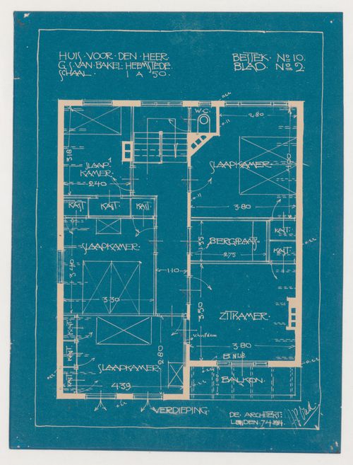
- Drawing DR1984:0009 for a shop and house for G.S. van Bakel (Heemstede) shows a design for an L-shaped plan, which differs from the rectangular plan of later blueprints DR1984:0479 - DR1984:0482. A cornice detail and revisions [?] to the elevation appear at the center right of drawing DR1984:0009. Blueprint DR1984:0482 has a key at the lower left which indicates that cross-hatched lines on the site plan indicate existing built areas (bestaande gebouwen), while single hatched lines indicate proposed areas of construction for the house and surroundings (te bouwen huis enz.).
DR1984:0480
Description:
- Drawing DR1984:0009 for a shop and house for G.S. van Bakel (Heemstede) shows a design for an L-shaped plan, which differs from the rectangular plan of later blueprints DR1984:0479 - DR1984:0482. A cornice detail and revisions [?] to the elevation appear at the center right of drawing DR1984:0009. Blueprint DR1984:0482 has a key at the lower left which indicates that cross-hatched lines on the site plan indicate existing built areas (bestaande gebouwen), while single hatched lines indicate proposed areas of construction for the house and surroundings (te bouwen huis enz.).
People:
Subject:
architecture
architecture
Date:
printed 1914
printed 1914
Title:
First floor plan for a house and shop with a rectangular plan for Mr. G.S. van Bakel, Heemstede, Netherlands
Actions:
DR1984:0480
Description:
- Drawing DR1984:0009 for a shop and house for G.S. van Bakel (Heemstede) shows a design for an L-shaped plan, which differs from the rectangular plan of later blueprints DR1984:0479 - DR1984:0482. A cornice detail and revisions [?] to the elevation appear at the center right of drawing DR1984:0009. Blueprint DR1984:0482 has a key at the lower left which indicates that cross-hatched lines on the site plan indicate existing built areas (bestaande gebouwen), while single hatched lines indicate proposed areas of construction for the house and surroundings (te bouwen huis enz.).
First floor plan for a house and shop with a rectangular plan for Mr. G.S. van Bakel, Heemstede, Netherlands
Actions:
DR1984:0480
Description:
- Drawing DR1984:0009 for a shop and house for G.S. van Bakel (Heemstede) shows a design for an L-shaped plan, which differs from the rectangular plan of later blueprints DR1984:0479 - DR1984:0482. A cornice detail and revisions [?] to the elevation appear at the center right of drawing DR1984:0009. Blueprint DR1984:0482 has a key at the lower left which indicates that cross-hatched lines on the site plan indicate existing built areas (bestaande gebouwen), while single hatched lines indicate proposed areas of construction for the house and surroundings (te bouwen huis enz.).
Form:
drawings
drawings
Date:
printed 1914
printed 1914
People:
Subject:
architecture
architecture


