5179 Results
Form:
photographs
photographs
Title:
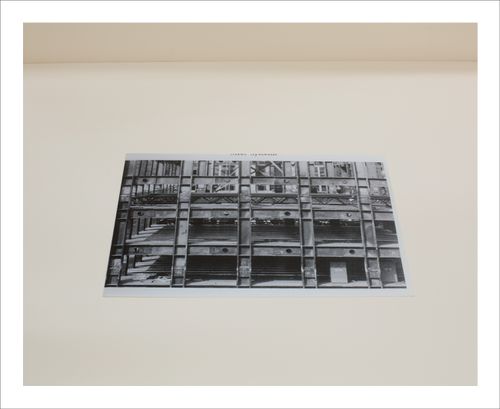
Proofs of Relevance: View of a copy print showing the steel systems of a building under construction
Proofs of Relevance: View of a copy print showing the steel systems of a building under construction
Actions:
Reference number:
PH2015:0002:042
Description:
Commissioned by the Canadian Centre for Architecture, Montréal, for "Proofs of Relevance," 2014
PH2015:0002:042
Description:
Commissioned by the Canadian Centre for Architecture, Montréal, for "Proofs of Relevance," 2014
People:
Date:
2014
2014
Title:
Proofs of Relevance: View of a copy print showing the steel systems of a building under construction
Actions:
PH2015:0002:042
Description:
Commissioned by the Canadian Centre for Architecture, Montréal, for "Proofs of Relevance," 2014
Proofs of Relevance: View of a copy print showing the steel systems of a building under construction
Actions:
PH2015:0002:042
Description:
Commissioned by the Canadian Centre for Architecture, Montréal, for "Proofs of Relevance," 2014
Form:
photographs
photographs
Date:
2014
2014
People:
Form:
photographs
photographs
Actions:
Reference number:
PH2015:0002:043
Description:
Commissioned by the Canadian Centre for Architecture, Montréal, for "Proofs of Relevance," 2014
PH2015:0002:043
Description:
Commissioned by the Canadian Centre for Architecture, Montréal, for "Proofs of Relevance," 2014
People:
Date:
2014
2014
Title:
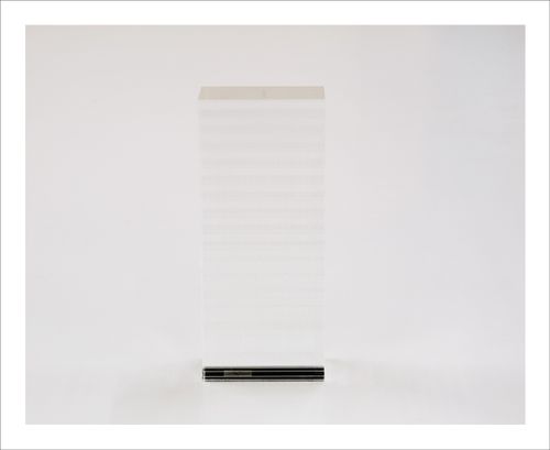
Proofs of Relevance: View of the model of one of the four Bioclimatic Towers, Abalos & Herreros (2001-06), Vitoria-Gasteiz, Spain
Actions:
PH2015:0002:043
Description:
Commissioned by the Canadian Centre for Architecture, Montréal, for "Proofs of Relevance," 2014
Proofs of Relevance: View of the model of one of the four Bioclimatic Towers, Abalos & Herreros (2001-06), Vitoria-Gasteiz, Spain
Actions:
PH2015:0002:043
Description:
Commissioned by the Canadian Centre for Architecture, Montréal, for "Proofs of Relevance," 2014
Form:
photographs
photographs
Date:
2014
2014
People:
Form:
photographs
photographs
Actions:
Reference number:
PH2015:0002:044
Description:
Commissioned by the Canadian Centre for Architecture, Montréal, for "Proofs of Relevance," 2014
PH2015:0002:044
Description:
Commissioned by the Canadian Centre for Architecture, Montréal, for "Proofs of Relevance," 2014
People:
Date:
2014
2014
Title:
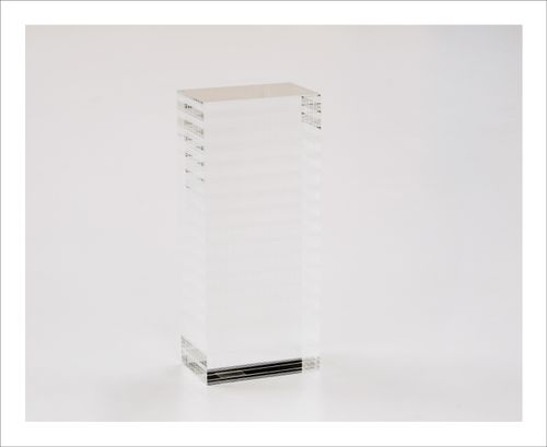
Proofs of Relevance: View of the model of one of the four Bioclimatic Towers, Abalos & Herreros (2001-06), Vitoria-Gasteiz, Spain
Actions:
PH2015:0002:044
Description:
Commissioned by the Canadian Centre for Architecture, Montréal, for "Proofs of Relevance," 2014
Proofs of Relevance: View of the model of one of the four Bioclimatic Towers, Abalos & Herreros (2001-06), Vitoria-Gasteiz, Spain
Actions:
PH2015:0002:044
Description:
Commissioned by the Canadian Centre for Architecture, Montréal, for "Proofs of Relevance," 2014
Form:
photographs
photographs
Date:
2014
2014
People:
Form:
photographs
photographs
Actions:
Reference number:
PH2015:0002:045
Description:
Commissioned by the Canadian Centre for Architecture, Montréal, for "Proofs of Relevance," 2014
PH2015:0002:045
Description:
Commissioned by the Canadian Centre for Architecture, Montréal, for "Proofs of Relevance," 2014
People:
Date:
2014
2014
Title:
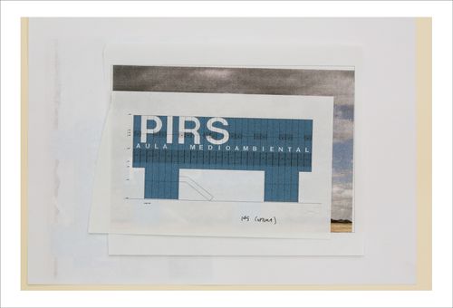
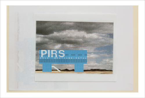
Proofs of Relevance: View of an elevation showing the Environment Education Centre, Abalos & Herreros (1999-2001), Arico, Tenerife, Spain
Actions:
PH2015:0002:045
Description:
Commissioned by the Canadian Centre for Architecture, Montréal, for "Proofs of Relevance," 2014
Proofs of Relevance: View of an elevation showing the Environment Education Centre, Abalos & Herreros (1999-2001), Arico, Tenerife, Spain
Actions:
PH2015:0002:045
Description:
Commissioned by the Canadian Centre for Architecture, Montréal, for "Proofs of Relevance," 2014
Form:
photographs
photographs
Date:
2014
2014
People:
Form:
photographs
photographs
Actions:
Reference number:
PH2015:0002:046
Description:
Commissioned by the Canadian Centre for Architecture, Montréal, for "Proofs of Relevance," 2014
PH2015:0002:046
Description:
Commissioned by the Canadian Centre for Architecture, Montréal, for "Proofs of Relevance," 2014
People:
Date:
2014
2014
Title:
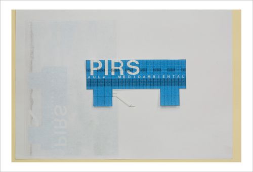
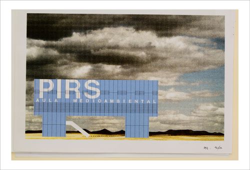
Proofs of Relevance: View of a photomontage showing the Environment Education Centre, Abalos & Herreros (1999-2001), Arico, Tenerife, Spain
Actions:
PH2015:0002:046
Description:
Commissioned by the Canadian Centre for Architecture, Montréal, for "Proofs of Relevance," 2014
Proofs of Relevance: View of a photomontage showing the Environment Education Centre, Abalos & Herreros (1999-2001), Arico, Tenerife, Spain
Actions:
PH2015:0002:046
Description:
Commissioned by the Canadian Centre for Architecture, Montréal, for "Proofs of Relevance," 2014
Form:
photographs
photographs
Date:
2014
2014
People:
Form:
photographs
photographs
Actions:
Reference number:
PH2015:0002:047
Description:
Commissioned by the Canadian Centre for Architecture, Montréal, for "Proofs of Relevance," 2014
PH2015:0002:047
Description:
Commissioned by the Canadian Centre for Architecture, Montréal, for "Proofs of Relevance," 2014
People:
Date:
2014
2014
Title:
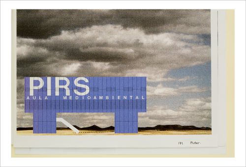
Proofs of Relevance: View of an elevation showing the Environment Education Centre, Abalos & Herreros (1999-2001), Arico, Tenerife, Spain
Actions:
PH2015:0002:047
Description:
Commissioned by the Canadian Centre for Architecture, Montréal, for "Proofs of Relevance," 2014
Proofs of Relevance: View of an elevation showing the Environment Education Centre, Abalos & Herreros (1999-2001), Arico, Tenerife, Spain
Actions:
PH2015:0002:047
Description:
Commissioned by the Canadian Centre for Architecture, Montréal, for "Proofs of Relevance," 2014
Form:
photographs
photographs
Date:
2014
2014
People:
Form:
photographs
photographs
Actions:
Reference number:
PH2015:0002:048
Description:
Commissioned by the Canadian Centre for Architecture, Montréal, for "Proofs of Relevance," 2014
PH2015:0002:048
Description:
Commissioned by the Canadian Centre for Architecture, Montréal, for "Proofs of Relevance," 2014
People:
Date:
2014
2014
Title:
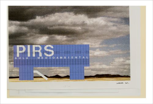
Proofs of Relevance: View of a photomontage showing the Environment Education Centre, Abalos & Herreros (1999-2001), Arico, Tenerife, Spain
Actions:
PH2015:0002:048
Description:
Commissioned by the Canadian Centre for Architecture, Montréal, for "Proofs of Relevance," 2014
Proofs of Relevance: View of a photomontage showing the Environment Education Centre, Abalos & Herreros (1999-2001), Arico, Tenerife, Spain
Actions:
PH2015:0002:048
Description:
Commissioned by the Canadian Centre for Architecture, Montréal, for "Proofs of Relevance," 2014
Form:
photographs
photographs
Date:
2014
2014
People:
Form:
photographs
photographs
Actions:
Reference number:
PH2015:0002:049
Description:
Commissioned by the Canadian Centre for Architecture, Montréal, for "Proofs of Relevance," 2014
PH2015:0002:049
Description:
Commissioned by the Canadian Centre for Architecture, Montréal, for "Proofs of Relevance," 2014
People:
Date:
2014
2014
Title:
Proofs of Relevance: View of a photomontage showing the Environment Education Centre, Abalos & Herreros (1999-2001), Arico, Tenerife, Spain
Actions:
PH2015:0002:049
Description:
Commissioned by the Canadian Centre for Architecture, Montréal, for "Proofs of Relevance," 2014
Proofs of Relevance: View of a photomontage showing the Environment Education Centre, Abalos & Herreros (1999-2001), Arico, Tenerife, Spain
Actions:
PH2015:0002:049
Description:
Commissioned by the Canadian Centre for Architecture, Montréal, for "Proofs of Relevance," 2014
Form:
photographs
photographs
Date:
2014
2014
People:
Form:
photographs
photographs
Actions:
Reference number:
PH2015:0002:050
Description:
Commissioned by the Canadian Centre for Architecture, Montréal, for "Proofs of Relevance," 2014
PH2015:0002:050
Description:
Commissioned by the Canadian Centre for Architecture, Montréal, for "Proofs of Relevance," 2014
People:
Date:
2014
2014
Title:
Proofs of Relevance: View of a photomontage showing the Environment Education Centre, Abalos & Herreros (1999-2001), Arico, Tenerife, Spain
Actions:
PH2015:0002:050
Description:
Commissioned by the Canadian Centre for Architecture, Montréal, for "Proofs of Relevance," 2014
Proofs of Relevance: View of a photomontage showing the Environment Education Centre, Abalos & Herreros (1999-2001), Arico, Tenerife, Spain
Actions:
PH2015:0002:050
Description:
Commissioned by the Canadian Centre for Architecture, Montréal, for "Proofs of Relevance," 2014
Form:
photographs
photographs
Date:
2014
2014
People:
Form:
photographs
photographs
Actions:
Reference number:
PH2015:0002:051
Description:
Commissioned by the Canadian Centre for Architecture, Montréal, for "Proofs of Relevance," 2014
PH2015:0002:051
Description:
Commissioned by the Canadian Centre for Architecture, Montréal, for "Proofs of Relevance," 2014
People:
Date:
2014
2014
Title:
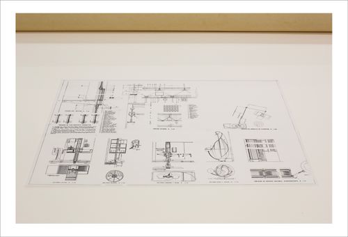
Proofs of Relevance: View of technical drawings showing the residential project and masterplan of Housing and City, Diagonal, Abalos & Herreros (1988-1989), Barcelone, Spain
Actions:
PH2015:0002:051
Description:
Commissioned by the Canadian Centre for Architecture, Montréal, for "Proofs of Relevance," 2014
Form:
photographs
photographs
Date:
2014
2014
People: