


11904 Results
Title:
Orban & Litolff
Orban & Litolff
Actions:
Reference number:
PH1986:0900.14
Description:
Album PH1986:0900.14 comprises 58 photographs of a private mansion located on square Frère-Orban and on Rue de la Science in Brussels, Belgium, designed by Michel Roux-Spitz. Photographs include 5 elevations of the building (PH1986:0900.14:001-PH1986:0900.14:004 are signed and dated by Michel Roux-Spitz), views of the building site, exterior views of the building, the courtyard, details of the windows and the doors. Interior views showing the staircases, living rooms with bookcases and furniture, fireplaces (one with ornamentation in bas-relief signed by A. Jamiot), several details of bas-relief ornamentations, 2 views of a dining room with a painted scene on walls and views of a hallway with a sculpture are included. Further research may confirm that some of these views are from the Litolff apartment referring to an apartment located on rue de Litolff in Paris, France.
PH1986:0900.14
Description:
Album PH1986:0900.14 comprises 58 photographs of a private mansion located on square Frère-Orban and on Rue de la Science in Brussels, Belgium, designed by Michel Roux-Spitz. Photographs include 5 elevations of the building (PH1986:0900.14:001-PH1986:0900.14:004 are signed and dated by Michel Roux-Spitz), views of the building site, exterior views of the building, the courtyard, details of the windows and the doors. Interior views showing the staircases, living rooms with bookcases and furniture, fireplaces (one with ornamentation in bas-relief signed by A. Jamiot), several details of bas-relief ornamentations, 2 views of a dining room with a painted scene on walls and views of a hallway with a sculpture are included. Further research may confirm that some of these views are from the Litolff apartment referring to an apartment located on rue de Litolff in Paris, France.
People:
Subject:
architecture, interior design, ornament, sculpture
architecture, interior design, ornament, sculpture
Date:
1931-1936
1931-1936
Title:
Orban & Litolff
Actions:
PH1986:0900.14
Description:
Album PH1986:0900.14 comprises 58 photographs of a private mansion located on square Frère-Orban and on Rue de la Science in Brussels, Belgium, designed by Michel Roux-Spitz. Photographs include 5 elevations of the building (PH1986:0900.14:001-PH1986:0900.14:004 are signed and dated by Michel Roux-Spitz), views of the building site, exterior views of the building, the courtyard, details of the windows and the doors. Interior views showing the staircases, living rooms with bookcases and furniture, fireplaces (one with ornamentation in bas-relief signed by A. Jamiot), several details of bas-relief ornamentations, 2 views of a dining room with a painted scene on walls and views of a hallway with a sculpture are included. Further research may confirm that some of these views are from the Litolff apartment referring to an apartment located on rue de Litolff in Paris, France.
Orban & Litolff
Actions:
PH1986:0900.14
Description:
Album PH1986:0900.14 comprises 58 photographs of a private mansion located on square Frère-Orban and on Rue de la Science in Brussels, Belgium, designed by Michel Roux-Spitz. Photographs include 5 elevations of the building (PH1986:0900.14:001-PH1986:0900.14:004 are signed and dated by Michel Roux-Spitz), views of the building site, exterior views of the building, the courtyard, details of the windows and the doors. Interior views showing the staircases, living rooms with bookcases and furniture, fireplaces (one with ornamentation in bas-relief signed by A. Jamiot), several details of bas-relief ornamentations, 2 views of a dining room with a painted scene on walls and views of a hallway with a sculpture are included. Further research may confirm that some of these views are from the Litolff apartment referring to an apartment located on rue de Litolff in Paris, France.
Date:
1931-1936
1931-1936
People:
Subject:
architecture, interior design, ornament, sculpture
architecture, interior design, ornament, sculpture
Level of archival description:
Project
Project
Reference number:
AP143.S4.D14
Description:
File documents an executed project for House VI, a weekend/vacation house designed for Richard and Suzanne Frank for a six-acre lot at Great Hollow Road, Cornwall, Connecticut. The file also includes material for renovations to House VI undertaken in 1983, 1986, and 1989-1990. Material in this file was produced between 1971 and 1989. The 1,500 square foot plan of House VI comprises a kitchen, dining room, living room and study on the ground floor, and a bedroom and bathroom on the second floor. The most notable formal and compositional ambiguities of House VI are the two staircases, one green, and the other red and positioned on the ceiling. Documents include drawings by Eisenman concerning the geometric operations at the origin of House VI (DR1994:0134:055-067), conceptual drawings (DR1994:0134:001-068; DR1994:0134:086-130; DR1994:0134:131-160), numerous colour studies of the elevations (DR1994:0134:262-343), a presentation panel (DR1994:0134:521) notes (DR1994:0134:779-782), and a first set of working drawings and "check set," completed on 30 Aug. 1973, (DR1994:0134:667-689). Documents also include drawings for major revisions which occurred from 3 October 1973 through August 1974, photocopies of photographs of the house under construction (DR1994:0134:783-805), and a copy of the site survey (DR1994:0134:806). Planned and executed renovations to House VI began in 1983. Documents relating to unexecuted renovations and additions of 1983 includes drawings (DR1994:0134:604-615), a "bid set" and annotated copies (DR1994:0134:552 and DR1994:0134:554-570; copies: DR1994:0134:646-655), and a photocopy of the site plan indicating Eisenman's initial ideas (DR1994:0134:224). Documents relating to unexecuted renovations and additions of 1986 includes seven drawings (DR1994:0134:553 and DR1994:0134:628-633). House VI was extensively rebuilt between 1988 and 1990. The renovations included the replacement of the exterior plywood walls, the insertion of steel reinforcement, a new roof with skylights, the replacement of the original stucco by a coat of Finestone, the repainting of the interior, and the addition of a plexiglas barrier to the staircase. Documents relating to the renovations of 1988-90 include original and photocopied detail drawings, an interior paint schedule by Eisenman's office, correspondence, original and photocopied technical literature, an incomplete copy of the specifications, and a copy of the original survey map (identical to DR1994:0134:806). There are also numerous photographs of the building before, during and after renovation, one photograph of presentation axonometrics for House VI, and one photograph of Eisenman's office. Documents relating to a publication on House VI include: notes (DR1994:0134:807-853), the book mock-up (DR1994:0134:854-855), and fragments of the original coloured transformation diagrams (DR1994:0134:530-531). File contains conceptual drawings, including plans, axonometrics, and sections - many black felt-tip pen and/or coloured felt-tip pen on tracing paper; and reprographic copies - mostly photocopies on wove paper. Design development drawings include site plans, plans, elevations, sections, and axonometrics - some graphite and/or coloured pencil on tracing paper and some pen and black ink and/or graphite on tracing vellum; and reprographic copies - some photocopies on wove paper and some sepia prints on mylar. Schematic drawings include site plans, plans, elevations, and sections - all pen and black ink on mylar; and reprographic copies - many blackline prints on wove paper. Working drawings include site plans, plans, elevations, sections, electrical drawings, HVAC drawings, structural drawings, and detail drawings - some coloured pencil on blueline prints on wove paper; and reprographic copies - mostly blueline prints on wove paper. Presentation drawings include plans, elevations, and axonometrics - some pen and black ink and/or transparent coloured adhesive film on mylar and some translucent adhesive coloured film on cardboard; and reprographic copies - mostly photocopies on wove paper. Model includes one finished model - grey, white, and silver paint on wood and Fome-Cor with plastic sheets. Notes and documents include manuscripts - mostly black felt-tip pen on wove paper; reprographic copies - mostly photocopies on wove paper; and a land surveyor plan - one blueline print on wove paper. Book project includes layout drawings - some black felt-tip pen on ruled paper; reprographic copies - all photocopies on wove paper; manuscripts - mostly black felt-tip pen on wove or ruled paper; one sample piece of grey cardboard used as backing for some of the presentation drawings; and sets of drawings in the form of book dummies - mostly pen and coloured ink and/or black felt-tip pen on photocopies on wove paper. Detail drawings include elevations, sections, details - mostly graphite on tracing paper. The linear cm of documents includes sets, reprographic copies and manuscripts. Notes and documents include elevations, sections, and details - some graphite on photocopies on wove paper; two sets of drawing copies, some with changes - mostly photocopies on wove paper; reprographic copies - mostly photocopies on wove paper; manuscripts - many graphite on wove paper; ephemera includes trade pamphlets; and photographs include colour images of House X prior to and during one of the renovations.
AP143.S4.D14
Description:
File documents an executed project for House VI, a weekend/vacation house designed for Richard and Suzanne Frank for a six-acre lot at Great Hollow Road, Cornwall, Connecticut. The file also includes material for renovations to House VI undertaken in 1983, 1986, and 1989-1990. Material in this file was produced between 1971 and 1989. The 1,500 square foot plan of House VI comprises a kitchen, dining room, living room and study on the ground floor, and a bedroom and bathroom on the second floor. The most notable formal and compositional ambiguities of House VI are the two staircases, one green, and the other red and positioned on the ceiling. Documents include drawings by Eisenman concerning the geometric operations at the origin of House VI (DR1994:0134:055-067), conceptual drawings (DR1994:0134:001-068; DR1994:0134:086-130; DR1994:0134:131-160), numerous colour studies of the elevations (DR1994:0134:262-343), a presentation panel (DR1994:0134:521) notes (DR1994:0134:779-782), and a first set of working drawings and "check set," completed on 30 Aug. 1973, (DR1994:0134:667-689). Documents also include drawings for major revisions which occurred from 3 October 1973 through August 1974, photocopies of photographs of the house under construction (DR1994:0134:783-805), and a copy of the site survey (DR1994:0134:806). Planned and executed renovations to House VI began in 1983. Documents relating to unexecuted renovations and additions of 1983 includes drawings (DR1994:0134:604-615), a "bid set" and annotated copies (DR1994:0134:552 and DR1994:0134:554-570; copies: DR1994:0134:646-655), and a photocopy of the site plan indicating Eisenman's initial ideas (DR1994:0134:224). Documents relating to unexecuted renovations and additions of 1986 includes seven drawings (DR1994:0134:553 and DR1994:0134:628-633). House VI was extensively rebuilt between 1988 and 1990. The renovations included the replacement of the exterior plywood walls, the insertion of steel reinforcement, a new roof with skylights, the replacement of the original stucco by a coat of Finestone, the repainting of the interior, and the addition of a plexiglas barrier to the staircase. Documents relating to the renovations of 1988-90 include original and photocopied detail drawings, an interior paint schedule by Eisenman's office, correspondence, original and photocopied technical literature, an incomplete copy of the specifications, and a copy of the original survey map (identical to DR1994:0134:806). There are also numerous photographs of the building before, during and after renovation, one photograph of presentation axonometrics for House VI, and one photograph of Eisenman's office. Documents relating to a publication on House VI include: notes (DR1994:0134:807-853), the book mock-up (DR1994:0134:854-855), and fragments of the original coloured transformation diagrams (DR1994:0134:530-531). File contains conceptual drawings, including plans, axonometrics, and sections - many black felt-tip pen and/or coloured felt-tip pen on tracing paper; and reprographic copies - mostly photocopies on wove paper. Design development drawings include site plans, plans, elevations, sections, and axonometrics - some graphite and/or coloured pencil on tracing paper and some pen and black ink and/or graphite on tracing vellum; and reprographic copies - some photocopies on wove paper and some sepia prints on mylar. Schematic drawings include site plans, plans, elevations, and sections - all pen and black ink on mylar; and reprographic copies - many blackline prints on wove paper. Working drawings include site plans, plans, elevations, sections, electrical drawings, HVAC drawings, structural drawings, and detail drawings - some coloured pencil on blueline prints on wove paper; and reprographic copies - mostly blueline prints on wove paper. Presentation drawings include plans, elevations, and axonometrics - some pen and black ink and/or transparent coloured adhesive film on mylar and some translucent adhesive coloured film on cardboard; and reprographic copies - mostly photocopies on wove paper. Model includes one finished model - grey, white, and silver paint on wood and Fome-Cor with plastic sheets. Notes and documents include manuscripts - mostly black felt-tip pen on wove paper; reprographic copies - mostly photocopies on wove paper; and a land surveyor plan - one blueline print on wove paper. Book project includes layout drawings - some black felt-tip pen on ruled paper; reprographic copies - all photocopies on wove paper; manuscripts - mostly black felt-tip pen on wove or ruled paper; one sample piece of grey cardboard used as backing for some of the presentation drawings; and sets of drawings in the form of book dummies - mostly pen and coloured ink and/or black felt-tip pen on photocopies on wove paper. Detail drawings include elevations, sections, details - mostly graphite on tracing paper. The linear cm of documents includes sets, reprographic copies and manuscripts. Notes and documents include elevations, sections, and details - some graphite on photocopies on wove paper; two sets of drawing copies, some with changes - mostly photocopies on wove paper; reprographic copies - mostly photocopies on wove paper; manuscripts - many graphite on wove paper; ephemera includes trade pamphlets; and photographs include colour images of House X prior to and during one of the renovations.
People:
Date:
1971-1989
1971-1989
Title:
House VI, Cornwall, Connecticut
Actions:
AP143.S4.D14
Description:
File documents an executed project for House VI, a weekend/vacation house designed for Richard and Suzanne Frank for a six-acre lot at Great Hollow Road, Cornwall, Connecticut. The file also includes material for renovations to House VI undertaken in 1983, 1986, and 1989-1990. Material in this file was produced between 1971 and 1989. The 1,500 square foot plan of House VI comprises a kitchen, dining room, living room and study on the ground floor, and a bedroom and bathroom on the second floor. The most notable formal and compositional ambiguities of House VI are the two staircases, one green, and the other red and positioned on the ceiling. Documents include drawings by Eisenman concerning the geometric operations at the origin of House VI (DR1994:0134:055-067), conceptual drawings (DR1994:0134:001-068; DR1994:0134:086-130; DR1994:0134:131-160), numerous colour studies of the elevations (DR1994:0134:262-343), a presentation panel (DR1994:0134:521) notes (DR1994:0134:779-782), and a first set of working drawings and "check set," completed on 30 Aug. 1973, (DR1994:0134:667-689). Documents also include drawings for major revisions which occurred from 3 October 1973 through August 1974, photocopies of photographs of the house under construction (DR1994:0134:783-805), and a copy of the site survey (DR1994:0134:806). Planned and executed renovations to House VI began in 1983. Documents relating to unexecuted renovations and additions of 1983 includes drawings (DR1994:0134:604-615), a "bid set" and annotated copies (DR1994:0134:552 and DR1994:0134:554-570; copies: DR1994:0134:646-655), and a photocopy of the site plan indicating Eisenman's initial ideas (DR1994:0134:224). Documents relating to unexecuted renovations and additions of 1986 includes seven drawings (DR1994:0134:553 and DR1994:0134:628-633). House VI was extensively rebuilt between 1988 and 1990. The renovations included the replacement of the exterior plywood walls, the insertion of steel reinforcement, a new roof with skylights, the replacement of the original stucco by a coat of Finestone, the repainting of the interior, and the addition of a plexiglas barrier to the staircase. Documents relating to the renovations of 1988-90 include original and photocopied detail drawings, an interior paint schedule by Eisenman's office, correspondence, original and photocopied technical literature, an incomplete copy of the specifications, and a copy of the original survey map (identical to DR1994:0134:806). There are also numerous photographs of the building before, during and after renovation, one photograph of presentation axonometrics for House VI, and one photograph of Eisenman's office. Documents relating to a publication on House VI include: notes (DR1994:0134:807-853), the book mock-up (DR1994:0134:854-855), and fragments of the original coloured transformation diagrams (DR1994:0134:530-531). File contains conceptual drawings, including plans, axonometrics, and sections - many black felt-tip pen and/or coloured felt-tip pen on tracing paper; and reprographic copies - mostly photocopies on wove paper. Design development drawings include site plans, plans, elevations, sections, and axonometrics - some graphite and/or coloured pencil on tracing paper and some pen and black ink and/or graphite on tracing vellum; and reprographic copies - some photocopies on wove paper and some sepia prints on mylar. Schematic drawings include site plans, plans, elevations, and sections - all pen and black ink on mylar; and reprographic copies - many blackline prints on wove paper. Working drawings include site plans, plans, elevations, sections, electrical drawings, HVAC drawings, structural drawings, and detail drawings - some coloured pencil on blueline prints on wove paper; and reprographic copies - mostly blueline prints on wove paper. Presentation drawings include plans, elevations, and axonometrics - some pen and black ink and/or transparent coloured adhesive film on mylar and some translucent adhesive coloured film on cardboard; and reprographic copies - mostly photocopies on wove paper. Model includes one finished model - grey, white, and silver paint on wood and Fome-Cor with plastic sheets. Notes and documents include manuscripts - mostly black felt-tip pen on wove paper; reprographic copies - mostly photocopies on wove paper; and a land surveyor plan - one blueline print on wove paper. Book project includes layout drawings - some black felt-tip pen on ruled paper; reprographic copies - all photocopies on wove paper; manuscripts - mostly black felt-tip pen on wove or ruled paper; one sample piece of grey cardboard used as backing for some of the presentation drawings; and sets of drawings in the form of book dummies - mostly pen and coloured ink and/or black felt-tip pen on photocopies on wove paper. Detail drawings include elevations, sections, details - mostly graphite on tracing paper. The linear cm of documents includes sets, reprographic copies and manuscripts. Notes and documents include elevations, sections, and details - some graphite on photocopies on wove paper; two sets of drawing copies, some with changes - mostly photocopies on wove paper; reprographic copies - mostly photocopies on wove paper; manuscripts - many graphite on wove paper; ephemera includes trade pamphlets; and photographs include colour images of House X prior to and during one of the renovations.
House VI, Cornwall, Connecticut
Actions:
AP143.S4.D14
Description:
File documents an executed project for House VI, a weekend/vacation house designed for Richard and Suzanne Frank for a six-acre lot at Great Hollow Road, Cornwall, Connecticut. The file also includes material for renovations to House VI undertaken in 1983, 1986, and 1989-1990. Material in this file was produced between 1971 and 1989. The 1,500 square foot plan of House VI comprises a kitchen, dining room, living room and study on the ground floor, and a bedroom and bathroom on the second floor. The most notable formal and compositional ambiguities of House VI are the two staircases, one green, and the other red and positioned on the ceiling. Documents include drawings by Eisenman concerning the geometric operations at the origin of House VI (DR1994:0134:055-067), conceptual drawings (DR1994:0134:001-068; DR1994:0134:086-130; DR1994:0134:131-160), numerous colour studies of the elevations (DR1994:0134:262-343), a presentation panel (DR1994:0134:521) notes (DR1994:0134:779-782), and a first set of working drawings and "check set," completed on 30 Aug. 1973, (DR1994:0134:667-689). Documents also include drawings for major revisions which occurred from 3 October 1973 through August 1974, photocopies of photographs of the house under construction (DR1994:0134:783-805), and a copy of the site survey (DR1994:0134:806). Planned and executed renovations to House VI began in 1983. Documents relating to unexecuted renovations and additions of 1983 includes drawings (DR1994:0134:604-615), a "bid set" and annotated copies (DR1994:0134:552 and DR1994:0134:554-570; copies: DR1994:0134:646-655), and a photocopy of the site plan indicating Eisenman's initial ideas (DR1994:0134:224). Documents relating to unexecuted renovations and additions of 1986 includes seven drawings (DR1994:0134:553 and DR1994:0134:628-633). House VI was extensively rebuilt between 1988 and 1990. The renovations included the replacement of the exterior plywood walls, the insertion of steel reinforcement, a new roof with skylights, the replacement of the original stucco by a coat of Finestone, the repainting of the interior, and the addition of a plexiglas barrier to the staircase. Documents relating to the renovations of 1988-90 include original and photocopied detail drawings, an interior paint schedule by Eisenman's office, correspondence, original and photocopied technical literature, an incomplete copy of the specifications, and a copy of the original survey map (identical to DR1994:0134:806). There are also numerous photographs of the building before, during and after renovation, one photograph of presentation axonometrics for House VI, and one photograph of Eisenman's office. Documents relating to a publication on House VI include: notes (DR1994:0134:807-853), the book mock-up (DR1994:0134:854-855), and fragments of the original coloured transformation diagrams (DR1994:0134:530-531). File contains conceptual drawings, including plans, axonometrics, and sections - many black felt-tip pen and/or coloured felt-tip pen on tracing paper; and reprographic copies - mostly photocopies on wove paper. Design development drawings include site plans, plans, elevations, sections, and axonometrics - some graphite and/or coloured pencil on tracing paper and some pen and black ink and/or graphite on tracing vellum; and reprographic copies - some photocopies on wove paper and some sepia prints on mylar. Schematic drawings include site plans, plans, elevations, and sections - all pen and black ink on mylar; and reprographic copies - many blackline prints on wove paper. Working drawings include site plans, plans, elevations, sections, electrical drawings, HVAC drawings, structural drawings, and detail drawings - some coloured pencil on blueline prints on wove paper; and reprographic copies - mostly blueline prints on wove paper. Presentation drawings include plans, elevations, and axonometrics - some pen and black ink and/or transparent coloured adhesive film on mylar and some translucent adhesive coloured film on cardboard; and reprographic copies - mostly photocopies on wove paper. Model includes one finished model - grey, white, and silver paint on wood and Fome-Cor with plastic sheets. Notes and documents include manuscripts - mostly black felt-tip pen on wove paper; reprographic copies - mostly photocopies on wove paper; and a land surveyor plan - one blueline print on wove paper. Book project includes layout drawings - some black felt-tip pen on ruled paper; reprographic copies - all photocopies on wove paper; manuscripts - mostly black felt-tip pen on wove or ruled paper; one sample piece of grey cardboard used as backing for some of the presentation drawings; and sets of drawings in the form of book dummies - mostly pen and coloured ink and/or black felt-tip pen on photocopies on wove paper. Detail drawings include elevations, sections, details - mostly graphite on tracing paper. The linear cm of documents includes sets, reprographic copies and manuscripts. Notes and documents include elevations, sections, and details - some graphite on photocopies on wove paper; two sets of drawing copies, some with changes - mostly photocopies on wove paper; reprographic copies - mostly photocopies on wove paper; manuscripts - many graphite on wove paper; ephemera includes trade pamphlets; and photographs include colour images of House X prior to and during one of the renovations.
Level of archival description:
File 14
File 14
Date:
1971-1989
1971-1989
People:
Level of archival description:
Project
Project
Reference number:
AP143.S4.D65
Description:
File documents the unexecuted project for the University Art Museum, Long Beach, California. Material in this file was produced between 1986 and 1988. California State University, Long Beach (CSULB), commissioned Eisenman/Robertson Architects to design an art museum adjacent to the main campus entrance. The 67,500-square-foot building was to comprise four galleries, a black-box theater, an auditorium, a cafe, conference rooms, a library, offices, preparation spaces, and storage vaults. The project, sited on a 23-acre arboretum, included landscaping; terraced sculpture courtyards, botanical gardens, and a two-acre pond. Eisenman linked the northern and southern parts of the arboretum by an elevated public walkway through the museum. Sets of drawings were presented on 8 and 30 April, 2 June, and 5 Aug. In the first design phase Eisenman explores the cartographic figures which form the basis of his artificial excavation when superposed: a series of sketches establishes the analogical relationships which fix the relative scales of the plans and produce the superpositions; another series contextualizes the superposed figures by placing them within the museum site (DR1987:0859:087-090). The second phase concerns the building; the working model shows the building carved out of a square pit, from which spring an oil derrick and a reconstruction of a recreational pier (Rainbow Pier, 1920s) used here as circulatory bridge (DR1987:0859:160). In the third phase the architect systematizes his archeological procedure by using five significant cartographic dates - 1849, 1889, 1949, 1989, 2049 - each corresponding to a specific superposition (see DR1987:0859:274-277). In the fourth phase, Eisenman simplifies the superposition of 2049 to a few iconic colour-coded forms: ranch (green), ranch house (blue), campus site (red), and water forms (river and pond) (gold). Material for the fourth phase includes three relief models, four presentation drawings, and a model (property of the CSULB) (relief models: DR1987:0859:001-003; drawings: DR1987:0859:004-008). Eisenman "inhabits" his artifical archeology by detailed planning of interior spaces, and gives substance to the cartographic traces in a series of sketch sections, perspectives, and working models. Working models reveal how the central "canal" area gradually became the museum's access point (DR1987:0859:484-490); the museum, galleries, offices, and preparation areas are on one side of this deep cut, while the cafeteria and black-box theater are on the other. The upper level was to house offices, meeting rooms, and the library. File contains audiovisual material, conceptual drawings, design development drawings, presentation drawings, reference drawings, working drawings, photographic materials, and textual records.
AP143.S4.D65
Description:
File documents the unexecuted project for the University Art Museum, Long Beach, California. Material in this file was produced between 1986 and 1988. California State University, Long Beach (CSULB), commissioned Eisenman/Robertson Architects to design an art museum adjacent to the main campus entrance. The 67,500-square-foot building was to comprise four galleries, a black-box theater, an auditorium, a cafe, conference rooms, a library, offices, preparation spaces, and storage vaults. The project, sited on a 23-acre arboretum, included landscaping; terraced sculpture courtyards, botanical gardens, and a two-acre pond. Eisenman linked the northern and southern parts of the arboretum by an elevated public walkway through the museum. Sets of drawings were presented on 8 and 30 April, 2 June, and 5 Aug. In the first design phase Eisenman explores the cartographic figures which form the basis of his artificial excavation when superposed: a series of sketches establishes the analogical relationships which fix the relative scales of the plans and produce the superpositions; another series contextualizes the superposed figures by placing them within the museum site (DR1987:0859:087-090). The second phase concerns the building; the working model shows the building carved out of a square pit, from which spring an oil derrick and a reconstruction of a recreational pier (Rainbow Pier, 1920s) used here as circulatory bridge (DR1987:0859:160). In the third phase the architect systematizes his archeological procedure by using five significant cartographic dates - 1849, 1889, 1949, 1989, 2049 - each corresponding to a specific superposition (see DR1987:0859:274-277). In the fourth phase, Eisenman simplifies the superposition of 2049 to a few iconic colour-coded forms: ranch (green), ranch house (blue), campus site (red), and water forms (river and pond) (gold). Material for the fourth phase includes three relief models, four presentation drawings, and a model (property of the CSULB) (relief models: DR1987:0859:001-003; drawings: DR1987:0859:004-008). Eisenman "inhabits" his artifical archeology by detailed planning of interior spaces, and gives substance to the cartographic traces in a series of sketch sections, perspectives, and working models. Working models reveal how the central "canal" area gradually became the museum's access point (DR1987:0859:484-490); the museum, galleries, offices, and preparation areas are on one side of this deep cut, while the cafeteria and black-box theater are on the other. The upper level was to house offices, meeting rooms, and the library. File contains audiovisual material, conceptual drawings, design development drawings, presentation drawings, reference drawings, working drawings, photographic materials, and textual records.
People:
Date:
1986-1988
1986-1988
Title:
University Art Museum
Actions:
AP143.S4.D65
Description:
File documents the unexecuted project for the University Art Museum, Long Beach, California. Material in this file was produced between 1986 and 1988. California State University, Long Beach (CSULB), commissioned Eisenman/Robertson Architects to design an art museum adjacent to the main campus entrance. The 67,500-square-foot building was to comprise four galleries, a black-box theater, an auditorium, a cafe, conference rooms, a library, offices, preparation spaces, and storage vaults. The project, sited on a 23-acre arboretum, included landscaping; terraced sculpture courtyards, botanical gardens, and a two-acre pond. Eisenman linked the northern and southern parts of the arboretum by an elevated public walkway through the museum. Sets of drawings were presented on 8 and 30 April, 2 June, and 5 Aug. In the first design phase Eisenman explores the cartographic figures which form the basis of his artificial excavation when superposed: a series of sketches establishes the analogical relationships which fix the relative scales of the plans and produce the superpositions; another series contextualizes the superposed figures by placing them within the museum site (DR1987:0859:087-090). The second phase concerns the building; the working model shows the building carved out of a square pit, from which spring an oil derrick and a reconstruction of a recreational pier (Rainbow Pier, 1920s) used here as circulatory bridge (DR1987:0859:160). In the third phase the architect systematizes his archeological procedure by using five significant cartographic dates - 1849, 1889, 1949, 1989, 2049 - each corresponding to a specific superposition (see DR1987:0859:274-277). In the fourth phase, Eisenman simplifies the superposition of 2049 to a few iconic colour-coded forms: ranch (green), ranch house (blue), campus site (red), and water forms (river and pond) (gold). Material for the fourth phase includes three relief models, four presentation drawings, and a model (property of the CSULB) (relief models: DR1987:0859:001-003; drawings: DR1987:0859:004-008). Eisenman "inhabits" his artifical archeology by detailed planning of interior spaces, and gives substance to the cartographic traces in a series of sketch sections, perspectives, and working models. Working models reveal how the central "canal" area gradually became the museum's access point (DR1987:0859:484-490); the museum, galleries, offices, and preparation areas are on one side of this deep cut, while the cafeteria and black-box theater are on the other. The upper level was to house offices, meeting rooms, and the library. File contains audiovisual material, conceptual drawings, design development drawings, presentation drawings, reference drawings, working drawings, photographic materials, and textual records.
University Art Museum
Actions:
AP143.S4.D65
Description:
File documents the unexecuted project for the University Art Museum, Long Beach, California. Material in this file was produced between 1986 and 1988. California State University, Long Beach (CSULB), commissioned Eisenman/Robertson Architects to design an art museum adjacent to the main campus entrance. The 67,500-square-foot building was to comprise four galleries, a black-box theater, an auditorium, a cafe, conference rooms, a library, offices, preparation spaces, and storage vaults. The project, sited on a 23-acre arboretum, included landscaping; terraced sculpture courtyards, botanical gardens, and a two-acre pond. Eisenman linked the northern and southern parts of the arboretum by an elevated public walkway through the museum. Sets of drawings were presented on 8 and 30 April, 2 June, and 5 Aug. In the first design phase Eisenman explores the cartographic figures which form the basis of his artificial excavation when superposed: a series of sketches establishes the analogical relationships which fix the relative scales of the plans and produce the superpositions; another series contextualizes the superposed figures by placing them within the museum site (DR1987:0859:087-090). The second phase concerns the building; the working model shows the building carved out of a square pit, from which spring an oil derrick and a reconstruction of a recreational pier (Rainbow Pier, 1920s) used here as circulatory bridge (DR1987:0859:160). In the third phase the architect systematizes his archeological procedure by using five significant cartographic dates - 1849, 1889, 1949, 1989, 2049 - each corresponding to a specific superposition (see DR1987:0859:274-277). In the fourth phase, Eisenman simplifies the superposition of 2049 to a few iconic colour-coded forms: ranch (green), ranch house (blue), campus site (red), and water forms (river and pond) (gold). Material for the fourth phase includes three relief models, four presentation drawings, and a model (property of the CSULB) (relief models: DR1987:0859:001-003; drawings: DR1987:0859:004-008). Eisenman "inhabits" his artifical archeology by detailed planning of interior spaces, and gives substance to the cartographic traces in a series of sketch sections, perspectives, and working models. Working models reveal how the central "canal" area gradually became the museum's access point (DR1987:0859:484-490); the museum, galleries, offices, and preparation areas are on one side of this deep cut, while the cafeteria and black-box theater are on the other. The upper level was to house offices, meeting rooms, and the library. File contains audiovisual material, conceptual drawings, design development drawings, presentation drawings, reference drawings, working drawings, photographic materials, and textual records.
Level of archival description:
File 65
File 65
Date:
1986-1988
1986-1988
People:
Form:
works of art
works of art
Reference number:
DR1984:0572
Description:
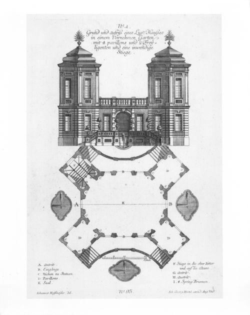
- DR1984:0572 and DR1984:0573 describe a theoretical project for a garden house consisting of a central block and four smaller pavilions. The central block, rectangular in plan and containing a single-storey, oval salon, or hall, is entered by means of curved stair ramps on front and back. The four pavilions, also rectangular in plan but two storeys in height, are joined at a forty-five degree angle to the four corners of the central block. On the main level the interior walls of the central hall and of three pavilions are articulated by statue niches. The fourth pavilion contains a staircase leading to the second floor. Except for the pavilions this upper level is open to the sky. At ground level four fountains are placed axially in the angles created by the pavilions. On the exterior the walls of the main floor are rusticated, while those of the pavilions at second-storey level are framed by an order of Corinthian pilasters.
DR1984:0572
Description:
- DR1984:0572 and DR1984:0573 describe a theoretical project for a garden house consisting of a central block and four smaller pavilions. The central block, rectangular in plan and containing a single-storey, oval salon, or hall, is entered by means of curved stair ramps on front and back. The four pavilions, also rectangular in plan but two storeys in height, are joined at a forty-five degree angle to the four corners of the central block. On the main level the interior walls of the central hall and of three pavilions are articulated by statue niches. The fourth pavilion contains a staircase leading to the second floor. Except for the pavilions this upper level is open to the sky. At ground level four fountains are placed axially in the angles created by the pavilions. On the exterior the walls of the main floor are rusticated, while those of the pavilions at second-storey level are framed by an order of Corinthian pilasters.
People:
Subject:
architecture, landscape architecture
architecture, landscape architecture
Date:
ca. 1735-ca. 1745
ca. 1735-ca. 1745
Title:
Ground floor plan and front elevation of a Garden Pleasure House
Actions:
DR1984:0572
Description:
- DR1984:0572 and DR1984:0573 describe a theoretical project for a garden house consisting of a central block and four smaller pavilions. The central block, rectangular in plan and containing a single-storey, oval salon, or hall, is entered by means of curved stair ramps on front and back. The four pavilions, also rectangular in plan but two storeys in height, are joined at a forty-five degree angle to the four corners of the central block. On the main level the interior walls of the central hall and of three pavilions are articulated by statue niches. The fourth pavilion contains a staircase leading to the second floor. Except for the pavilions this upper level is open to the sky. At ground level four fountains are placed axially in the angles created by the pavilions. On the exterior the walls of the main floor are rusticated, while those of the pavilions at second-storey level are framed by an order of Corinthian pilasters.
Ground floor plan and front elevation of a Garden Pleasure House
Actions:
DR1984:0572
Description:
- DR1984:0572 and DR1984:0573 describe a theoretical project for a garden house consisting of a central block and four smaller pavilions. The central block, rectangular in plan and containing a single-storey, oval salon, or hall, is entered by means of curved stair ramps on front and back. The four pavilions, also rectangular in plan but two storeys in height, are joined at a forty-five degree angle to the four corners of the central block. On the main level the interior walls of the central hall and of three pavilions are articulated by statue niches. The fourth pavilion contains a staircase leading to the second floor. Except for the pavilions this upper level is open to the sky. At ground level four fountains are placed axially in the angles created by the pavilions. On the exterior the walls of the main floor are rusticated, while those of the pavilions at second-storey level are framed by an order of Corinthian pilasters.
Form:
works of art
works of art
Date:
ca. 1735-ca. 1745
ca. 1735-ca. 1745
People:
Subject:
architecture, landscape architecture
architecture, landscape architecture
Form:
textual records
textual records
Actions:
Reference number:
ARCH257199
Description:
newspapers and magazines featuring articles on various projects - Hosptals 1977, Construction Sightlines 1979, Canadian Architect Yearbook 1978, Western Living 1971, Time 1967, Canadian Interiors 1970, SFU Review, UBC Reports Jan. 1973, Journal of Commerce 1978, Wood World 1972, Erickson/Massey and Their Works, Canadian Architect 1957.
ARCH257199
Description:
newspapers and magazines featuring articles on various projects - Hosptals 1977, Construction Sightlines 1979, Canadian Architect Yearbook 1978, Western Living 1971, Time 1967, Canadian Interiors 1970, SFU Review, UBC Reports Jan. 1973, Journal of Commerce 1978, Wood World 1972, Erickson/Massey and Their Works, Canadian Architect 1957.
People:
Title:
Newspapers and magazines featuring articles on various projects
Actions:
ARCH257199
Description:
newspapers and magazines featuring articles on various projects - Hosptals 1977, Construction Sightlines 1979, Canadian Architect Yearbook 1978, Western Living 1971, Time 1967, Canadian Interiors 1970, SFU Review, UBC Reports Jan. 1973, Journal of Commerce 1978, Wood World 1972, Erickson/Massey and Their Works, Canadian Architect 1957.
Newspapers and magazines featuring articles on various projects
Actions:
ARCH257199
Description:
newspapers and magazines featuring articles on various projects - Hosptals 1977, Construction Sightlines 1979, Canadian Architect Yearbook 1978, Western Living 1971, Time 1967, Canadian Interiors 1970, SFU Review, UBC Reports Jan. 1973, Journal of Commerce 1978, Wood World 1972, Erickson/Massey and Their Works, Canadian Architect 1957.
Form:
textual records
textual records
People:
Form:
photographs
photographs
Actions:
Reference number:
ARCH268722
Description:
Contains photographic materials on 7 projects by Abalos & Herreros used at a conference: - Recualificación del espacio público de Ramos, AP164.S1.1997.D7 (15 slides: aerial and landscape views, site plan and collages); - Aula medioambiental y oficinas, Arico, Tenerife, AP164.S1.1998.D1 (53 slides: interior, exterior and aerial views, sketches and plans); - Plaza y torre Woermann, Las Palmas, AP164.S1.2001.D7 (48 slides: plans, presentation documents, exterior views, models, etc.); - El mirador: torre mixta en la bahía de Algeciras, AP164.S1.1999.D10 (21 slides: plans, aerial and landscape views, models and maps); - Delegación de hacienda, Almería, AP164.S1.1997.D8 (42 slides: plans, models, maps, aerial views and collages); - Es Pil•larí, AP164.S1.2000.D5 (32 slides: aerial and landscape views, plans, drawings, site plans, etc.); - Barcelona Forum 2004, AP164.S1.2000.D9 (7 slides: plans and site plans).
ARCH268722
Description:
Contains photographic materials on 7 projects by Abalos & Herreros used at a conference: - Recualificación del espacio público de Ramos, AP164.S1.1997.D7 (15 slides: aerial and landscape views, site plan and collages); - Aula medioambiental y oficinas, Arico, Tenerife, AP164.S1.1998.D1 (53 slides: interior, exterior and aerial views, sketches and plans); - Plaza y torre Woermann, Las Palmas, AP164.S1.2001.D7 (48 slides: plans, presentation documents, exterior views, models, etc.); - El mirador: torre mixta en la bahía de Algeciras, AP164.S1.1999.D10 (21 slides: plans, aerial and landscape views, models and maps); - Delegación de hacienda, Almería, AP164.S1.1997.D8 (42 slides: plans, models, maps, aerial views and collages); - Es Pil•larí, AP164.S1.2000.D5 (32 slides: aerial and landscape views, plans, drawings, site plans, etc.); - Barcelona Forum 2004, AP164.S1.2000.D9 (7 slides: plans and site plans).
People:
Date:
between 1997 and 2005
between 1997 and 2005
Title:
Ring binder with photographic materials related to seven projects by Abalos & Herreros used at a conference
Actions:
ARCH268722
Description:
Contains photographic materials on 7 projects by Abalos & Herreros used at a conference: - Recualificación del espacio público de Ramos, AP164.S1.1997.D7 (15 slides: aerial and landscape views, site plan and collages); - Aula medioambiental y oficinas, Arico, Tenerife, AP164.S1.1998.D1 (53 slides: interior, exterior and aerial views, sketches and plans); - Plaza y torre Woermann, Las Palmas, AP164.S1.2001.D7 (48 slides: plans, presentation documents, exterior views, models, etc.); - El mirador: torre mixta en la bahía de Algeciras, AP164.S1.1999.D10 (21 slides: plans, aerial and landscape views, models and maps); - Delegación de hacienda, Almería, AP164.S1.1997.D8 (42 slides: plans, models, maps, aerial views and collages); - Es Pil•larí, AP164.S1.2000.D5 (32 slides: aerial and landscape views, plans, drawings, site plans, etc.); - Barcelona Forum 2004, AP164.S1.2000.D9 (7 slides: plans and site plans).
Ring binder with photographic materials related to seven projects by Abalos & Herreros used at a conference
Actions:
ARCH268722
Description:
Contains photographic materials on 7 projects by Abalos & Herreros used at a conference: - Recualificación del espacio público de Ramos, AP164.S1.1997.D7 (15 slides: aerial and landscape views, site plan and collages); - Aula medioambiental y oficinas, Arico, Tenerife, AP164.S1.1998.D1 (53 slides: interior, exterior and aerial views, sketches and plans); - Plaza y torre Woermann, Las Palmas, AP164.S1.2001.D7 (48 slides: plans, presentation documents, exterior views, models, etc.); - El mirador: torre mixta en la bahía de Algeciras, AP164.S1.1999.D10 (21 slides: plans, aerial and landscape views, models and maps); - Delegación de hacienda, Almería, AP164.S1.1997.D8 (42 slides: plans, models, maps, aerial views and collages); - Es Pil•larí, AP164.S1.2000.D5 (32 slides: aerial and landscape views, plans, drawings, site plans, etc.); - Barcelona Forum 2004, AP164.S1.2000.D9 (7 slides: plans and site plans).
Form:
photographs
photographs
Date:
between 1997 and 2005
between 1997 and 2005
People:
Form:
exhibitions
exhibitions
Title:
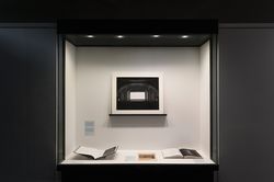
Mirrors / Miroirs
Mirrors / Miroirs
Actions:
Description:
Mirrors/ Miroirs is conceived through an indirect dialogue with the exhibition Besides, History: Go Hasegawa, Kersten Geers, David Van Severen, a project rooted in the shared references and resonances between the work of two contemporary practices in the presence of history. If Besides, History is premised on impressions of one office’s work registered through(...)
Mirrors/ Miroirs is conceived through an indirect dialogue with the exhibition Besides, History: Go Hasegawa, Kersten Geers, David Van Severen, a project rooted in the shared references and resonances between the work of two contemporary practices in the presence of history. If Besides, History is premised on impressions of one office’s work registered through(...)
Location:
Hall cases
Hall cases
Date:
22 June 2017 to 14 January 2018
22 June 2017 to 14 January 2018
Title:
Mirrors / Miroirs
Actions:
Description:
Mirrors/ Miroirs is conceived through an indirect dialogue with the exhibition Besides, History: Go Hasegawa, Kersten Geers, David Van Severen, a project rooted in the shared references and resonances between the work of two contemporary practices in the presence of history. If Besides, History is premised on impressions of one office’s work registered through(...)
Mirrors / Miroirs
Actions:
Description:
Mirrors/ Miroirs is conceived through an indirect dialogue with the exhibition Besides, History: Go Hasegawa, Kersten Geers, David Van Severen, a project rooted in the shared references and resonances between the work of two contemporary practices in the presence of history. If Besides, History is premised on impressions of one office’s work registered through(...)
Form:
exhibitions
exhibitions
Date:
22 June 2017 to
14 January 2018
22 June 2017 to
14 January 2018
Location:
Hall cases
Hall cases
Level of archival description:
Project
Project
Reference number:
AP178.S1.1988.PR07
Description:
This project series documents the Reconstrução do Chiado in Lisbon, Portugal. The office's archives identified this project as 58/80. The office assigned the dates 1988-1998 for this project. Chiado is a historic district in the center of Lisbon, Portugal, and a linchpin between the Baixa Pombalina and the Bairro Alto Hill. After a devastating earthquake in 1755, the city was rebuilt and reorganized by military architects and engineers. The Pombaline style, specific to Lisbon, includes pre-fabricated anti-seismic structure and sober style. On August 25, 1988, a fire started in one of the oldest department stores of Lisbon, the Grandella building, damaging partially or totally seventeen buildings, between the Rua Do Carmo, Rua Nova do Almada and Rua Garret. Álvaro Siza was selected by the mayor of Lisbon, Nuno Krus Abecasis, to reorganize and rebuild the district. After public consultations, it was decided to maintain the historic image of the Chiado by restoring the façades and ornamentations. Adjustments by Siza include introducing residential and cultural functions to the district, with the exception of the Grandes Armazéns building and the Grandella building, which had their own program. As Siza said himself: "It’s not about drawing a new section of the city, but rather just introducing corrections and adjustments, reinforce the whole city." Siza started to work on the layout plan in January 1989 and presented it to the municipal authorities of Lisbon in April 1990. The reconstruction of the Chiado had several goals, but there were two general concepts behind his plan. The aesthetic aspect of the program included restorations of buildings to reinstitute the historical spirit of the district. The spatial reorganization, in a really Siza way, focused on finding architectural solutions that would bring more functionality to the city. The idea was to think of the reconstruction in relation with the urban revitalization of the Baixa Pombalina and to maintain as much as possible the patrimonial value of the district. Siza's intentions were to stimulate the commercial and residential functions of the district, which was on the decline over the last years prior to the fire. Some of the measures taken were: improving the traffic fluidity; creating parking spaces for the future residents and shopkeepers, improving the access to stores and others facilities, creating a staired passageway between Rua do Crucifixo and Rua Nova do Almada, and a pedestrian passageway between the rear of those buildings giving onto Rua Garret and Rua Do Carmo. They also studied the integration of a subway station to the district. Municipal authorities decided to rebuild or restore the original facades, reorganize the interior and improve the safety of the buildings. The biggest challenge was to convert the Grandes Armazéns do Chiado into a hotel and rebuild the Grandella with its original 20th century façade, while rethinking the interior division(s?) in order to add different functions to the building, including offices and leisure and cultural facilities. The reconstruction plan was divided into six distinct blocks: Bloco A, Bloco B, Bloco C, Bloco D, Bloco E, and Bloco F. Each Block includes several buildings and each was individually numbered. The first three blocks (A, B, C) were the most damaged, and required massive work, stonework, technical and mechanical work, replacing doors and windows, as well as repainting, repaving, and restoring decorative elements. Reconstruction for Blocks D, E, and F, which are less documented in the fonds, focused on making changes that complemented the neighboring building. Siza also worked specifically on the Edifício Castro e Melo, Câmara Chaves, Edifício Leonel, Edifício Grandella, and Recuperaçäo do Edifício dos Grandes Armazéns. The rest of the buildings were restored by other architects and firms. "Chiado" is often referring to two different things: the districts between the Baixa Pombalina and the Bairro Alto Hill, as well as a building, also known as the Hotel do Chiado. To avoid confusion, in this finding aid the term "Chiado" is always referring to the district, and the Chiado building will be referred to as the Grandes Armazéns do Chiado building. To fully understand the nature of the project, it is important to comprehend the reconstruction of the Chiado as a whole project, rather than as individual components. Siza himself saw the Chiado as one big building. Bloco A (plots 7,8,9,10,11 and 20) Bloco B (plots 12, 13, 14/15 and 16) Bloco C (plots 2, 3 and 6) Bloco D (plots 4 and 5) Bloco E (plots 1,17,18 and 19) This project series includes eleven subseries : Subseries 1) AP178.S1.1988.PR07.SS1 Master plans and exterior spaces, Reconstruction of Chiado, 2) AP178.S1.1988.PR07.SS2 Bloco A, 3) AP178.S1.1988.PR07.SS3 Edificio Camara Chaves building, 4) AP178.S1.1988.PR07.SS4 Edifício Castro e Melo, 5) AP178.S1.1988.PR07.SS5 Bloco B, 6) AP178.S1.1988.PR07.SS6– Bloco, B Chiado, Edifício Leonel, Lisboa, Portugal (1988-1998), 7) AP178.S1.1988.PR07.SS7 Bloco C, 8) AP178.S1.1988.PR07.SS8 - Bloco C, Chiado, Recuperaçäo do Edifício Grandella, 9) AP178.S1.1988.PR07.SS9 - Bloco C, Chiado, Recuperaçäo do Edifício dos Grandes Armazéns, 10) AP178.S1.1988.PR07.SS10 Ligacao Pedonal do Patio B, 11) AP178.S1.1988.PR07.SS11 Chiado, Estação de Metropolitano Baixa Chiado. It is important to note that the project AP178.S1.1994.PR08 Renovação do Elevador de Santa Justa, Chiado, 1994 is also related to the Reconstruction of the Chiado. All documentation for this project series, including the project subseries, has been kept together to maintain the office's arrangement.
AP178.S1.1988.PR07
Description:
This project series documents the Reconstrução do Chiado in Lisbon, Portugal. The office's archives identified this project as 58/80. The office assigned the dates 1988-1998 for this project. Chiado is a historic district in the center of Lisbon, Portugal, and a linchpin between the Baixa Pombalina and the Bairro Alto Hill. After a devastating earthquake in 1755, the city was rebuilt and reorganized by military architects and engineers. The Pombaline style, specific to Lisbon, includes pre-fabricated anti-seismic structure and sober style. On August 25, 1988, a fire started in one of the oldest department stores of Lisbon, the Grandella building, damaging partially or totally seventeen buildings, between the Rua Do Carmo, Rua Nova do Almada and Rua Garret. Álvaro Siza was selected by the mayor of Lisbon, Nuno Krus Abecasis, to reorganize and rebuild the district. After public consultations, it was decided to maintain the historic image of the Chiado by restoring the façades and ornamentations. Adjustments by Siza include introducing residential and cultural functions to the district, with the exception of the Grandes Armazéns building and the Grandella building, which had their own program. As Siza said himself: "It’s not about drawing a new section of the city, but rather just introducing corrections and adjustments, reinforce the whole city." Siza started to work on the layout plan in January 1989 and presented it to the municipal authorities of Lisbon in April 1990. The reconstruction of the Chiado had several goals, but there were two general concepts behind his plan. The aesthetic aspect of the program included restorations of buildings to reinstitute the historical spirit of the district. The spatial reorganization, in a really Siza way, focused on finding architectural solutions that would bring more functionality to the city. The idea was to think of the reconstruction in relation with the urban revitalization of the Baixa Pombalina and to maintain as much as possible the patrimonial value of the district. Siza's intentions were to stimulate the commercial and residential functions of the district, which was on the decline over the last years prior to the fire. Some of the measures taken were: improving the traffic fluidity; creating parking spaces for the future residents and shopkeepers, improving the access to stores and others facilities, creating a staired passageway between Rua do Crucifixo and Rua Nova do Almada, and a pedestrian passageway between the rear of those buildings giving onto Rua Garret and Rua Do Carmo. They also studied the integration of a subway station to the district. Municipal authorities decided to rebuild or restore the original facades, reorganize the interior and improve the safety of the buildings. The biggest challenge was to convert the Grandes Armazéns do Chiado into a hotel and rebuild the Grandella with its original 20th century façade, while rethinking the interior division(s?) in order to add different functions to the building, including offices and leisure and cultural facilities. The reconstruction plan was divided into six distinct blocks: Bloco A, Bloco B, Bloco C, Bloco D, Bloco E, and Bloco F. Each Block includes several buildings and each was individually numbered. The first three blocks (A, B, C) were the most damaged, and required massive work, stonework, technical and mechanical work, replacing doors and windows, as well as repainting, repaving, and restoring decorative elements. Reconstruction for Blocks D, E, and F, which are less documented in the fonds, focused on making changes that complemented the neighboring building. Siza also worked specifically on the Edifício Castro e Melo, Câmara Chaves, Edifício Leonel, Edifício Grandella, and Recuperaçäo do Edifício dos Grandes Armazéns. The rest of the buildings were restored by other architects and firms. "Chiado" is often referring to two different things: the districts between the Baixa Pombalina and the Bairro Alto Hill, as well as a building, also known as the Hotel do Chiado. To avoid confusion, in this finding aid the term "Chiado" is always referring to the district, and the Chiado building will be referred to as the Grandes Armazéns do Chiado building. To fully understand the nature of the project, it is important to comprehend the reconstruction of the Chiado as a whole project, rather than as individual components. Siza himself saw the Chiado as one big building. Bloco A (plots 7,8,9,10,11 and 20) Bloco B (plots 12, 13, 14/15 and 16) Bloco C (plots 2, 3 and 6) Bloco D (plots 4 and 5) Bloco E (plots 1,17,18 and 19) This project series includes eleven subseries : Subseries 1) AP178.S1.1988.PR07.SS1 Master plans and exterior spaces, Reconstruction of Chiado, 2) AP178.S1.1988.PR07.SS2 Bloco A, 3) AP178.S1.1988.PR07.SS3 Edificio Camara Chaves building, 4) AP178.S1.1988.PR07.SS4 Edifício Castro e Melo, 5) AP178.S1.1988.PR07.SS5 Bloco B, 6) AP178.S1.1988.PR07.SS6– Bloco, B Chiado, Edifício Leonel, Lisboa, Portugal (1988-1998), 7) AP178.S1.1988.PR07.SS7 Bloco C, 8) AP178.S1.1988.PR07.SS8 - Bloco C, Chiado, Recuperaçäo do Edifício Grandella, 9) AP178.S1.1988.PR07.SS9 - Bloco C, Chiado, Recuperaçäo do Edifício dos Grandes Armazéns, 10) AP178.S1.1988.PR07.SS10 Ligacao Pedonal do Patio B, 11) AP178.S1.1988.PR07.SS11 Chiado, Estação de Metropolitano Baixa Chiado. It is important to note that the project AP178.S1.1994.PR08 Renovação do Elevador de Santa Justa, Chiado, 1994 is also related to the Reconstruction of the Chiado. All documentation for this project series, including the project subseries, has been kept together to maintain the office's arrangement.
People:
Date:
1942-2012
1942-2012
Title:
Reconstrução do Chiado [Reconstruction of the Chiado area], Lisbon, Portugal (1988-1998)
Actions:
AP178.S1.1988.PR07
Description:
This project series documents the Reconstrução do Chiado in Lisbon, Portugal. The office's archives identified this project as 58/80. The office assigned the dates 1988-1998 for this project. Chiado is a historic district in the center of Lisbon, Portugal, and a linchpin between the Baixa Pombalina and the Bairro Alto Hill. After a devastating earthquake in 1755, the city was rebuilt and reorganized by military architects and engineers. The Pombaline style, specific to Lisbon, includes pre-fabricated anti-seismic structure and sober style. On August 25, 1988, a fire started in one of the oldest department stores of Lisbon, the Grandella building, damaging partially or totally seventeen buildings, between the Rua Do Carmo, Rua Nova do Almada and Rua Garret. Álvaro Siza was selected by the mayor of Lisbon, Nuno Krus Abecasis, to reorganize and rebuild the district. After public consultations, it was decided to maintain the historic image of the Chiado by restoring the façades and ornamentations. Adjustments by Siza include introducing residential and cultural functions to the district, with the exception of the Grandes Armazéns building and the Grandella building, which had their own program. As Siza said himself: "It’s not about drawing a new section of the city, but rather just introducing corrections and adjustments, reinforce the whole city." Siza started to work on the layout plan in January 1989 and presented it to the municipal authorities of Lisbon in April 1990. The reconstruction of the Chiado had several goals, but there were two general concepts behind his plan. The aesthetic aspect of the program included restorations of buildings to reinstitute the historical spirit of the district. The spatial reorganization, in a really Siza way, focused on finding architectural solutions that would bring more functionality to the city. The idea was to think of the reconstruction in relation with the urban revitalization of the Baixa Pombalina and to maintain as much as possible the patrimonial value of the district. Siza's intentions were to stimulate the commercial and residential functions of the district, which was on the decline over the last years prior to the fire. Some of the measures taken were: improving the traffic fluidity; creating parking spaces for the future residents and shopkeepers, improving the access to stores and others facilities, creating a staired passageway between Rua do Crucifixo and Rua Nova do Almada, and a pedestrian passageway between the rear of those buildings giving onto Rua Garret and Rua Do Carmo. They also studied the integration of a subway station to the district. Municipal authorities decided to rebuild or restore the original facades, reorganize the interior and improve the safety of the buildings. The biggest challenge was to convert the Grandes Armazéns do Chiado into a hotel and rebuild the Grandella with its original 20th century façade, while rethinking the interior division(s?) in order to add different functions to the building, including offices and leisure and cultural facilities. The reconstruction plan was divided into six distinct blocks: Bloco A, Bloco B, Bloco C, Bloco D, Bloco E, and Bloco F. Each Block includes several buildings and each was individually numbered. The first three blocks (A, B, C) were the most damaged, and required massive work, stonework, technical and mechanical work, replacing doors and windows, as well as repainting, repaving, and restoring decorative elements. Reconstruction for Blocks D, E, and F, which are less documented in the fonds, focused on making changes that complemented the neighboring building. Siza also worked specifically on the Edifício Castro e Melo, Câmara Chaves, Edifício Leonel, Edifício Grandella, and Recuperaçäo do Edifício dos Grandes Armazéns. The rest of the buildings were restored by other architects and firms. "Chiado" is often referring to two different things: the districts between the Baixa Pombalina and the Bairro Alto Hill, as well as a building, also known as the Hotel do Chiado. To avoid confusion, in this finding aid the term "Chiado" is always referring to the district, and the Chiado building will be referred to as the Grandes Armazéns do Chiado building. To fully understand the nature of the project, it is important to comprehend the reconstruction of the Chiado as a whole project, rather than as individual components. Siza himself saw the Chiado as one big building. Bloco A (plots 7,8,9,10,11 and 20) Bloco B (plots 12, 13, 14/15 and 16) Bloco C (plots 2, 3 and 6) Bloco D (plots 4 and 5) Bloco E (plots 1,17,18 and 19) This project series includes eleven subseries : Subseries 1) AP178.S1.1988.PR07.SS1 Master plans and exterior spaces, Reconstruction of Chiado, 2) AP178.S1.1988.PR07.SS2 Bloco A, 3) AP178.S1.1988.PR07.SS3 Edificio Camara Chaves building, 4) AP178.S1.1988.PR07.SS4 Edifício Castro e Melo, 5) AP178.S1.1988.PR07.SS5 Bloco B, 6) AP178.S1.1988.PR07.SS6– Bloco, B Chiado, Edifício Leonel, Lisboa, Portugal (1988-1998), 7) AP178.S1.1988.PR07.SS7 Bloco C, 8) AP178.S1.1988.PR07.SS8 - Bloco C, Chiado, Recuperaçäo do Edifício Grandella, 9) AP178.S1.1988.PR07.SS9 - Bloco C, Chiado, Recuperaçäo do Edifício dos Grandes Armazéns, 10) AP178.S1.1988.PR07.SS10 Ligacao Pedonal do Patio B, 11) AP178.S1.1988.PR07.SS11 Chiado, Estação de Metropolitano Baixa Chiado. It is important to note that the project AP178.S1.1994.PR08 Renovação do Elevador de Santa Justa, Chiado, 1994 is also related to the Reconstruction of the Chiado. All documentation for this project series, including the project subseries, has been kept together to maintain the office's arrangement.
Reconstrução do Chiado [Reconstruction of the Chiado area], Lisbon, Portugal (1988-1998)
Actions:
AP178.S1.1988.PR07
Description:
This project series documents the Reconstrução do Chiado in Lisbon, Portugal. The office's archives identified this project as 58/80. The office assigned the dates 1988-1998 for this project. Chiado is a historic district in the center of Lisbon, Portugal, and a linchpin between the Baixa Pombalina and the Bairro Alto Hill. After a devastating earthquake in 1755, the city was rebuilt and reorganized by military architects and engineers. The Pombaline style, specific to Lisbon, includes pre-fabricated anti-seismic structure and sober style. On August 25, 1988, a fire started in one of the oldest department stores of Lisbon, the Grandella building, damaging partially or totally seventeen buildings, between the Rua Do Carmo, Rua Nova do Almada and Rua Garret. Álvaro Siza was selected by the mayor of Lisbon, Nuno Krus Abecasis, to reorganize and rebuild the district. After public consultations, it was decided to maintain the historic image of the Chiado by restoring the façades and ornamentations. Adjustments by Siza include introducing residential and cultural functions to the district, with the exception of the Grandes Armazéns building and the Grandella building, which had their own program. As Siza said himself: "It’s not about drawing a new section of the city, but rather just introducing corrections and adjustments, reinforce the whole city." Siza started to work on the layout plan in January 1989 and presented it to the municipal authorities of Lisbon in April 1990. The reconstruction of the Chiado had several goals, but there were two general concepts behind his plan. The aesthetic aspect of the program included restorations of buildings to reinstitute the historical spirit of the district. The spatial reorganization, in a really Siza way, focused on finding architectural solutions that would bring more functionality to the city. The idea was to think of the reconstruction in relation with the urban revitalization of the Baixa Pombalina and to maintain as much as possible the patrimonial value of the district. Siza's intentions were to stimulate the commercial and residential functions of the district, which was on the decline over the last years prior to the fire. Some of the measures taken were: improving the traffic fluidity; creating parking spaces for the future residents and shopkeepers, improving the access to stores and others facilities, creating a staired passageway between Rua do Crucifixo and Rua Nova do Almada, and a pedestrian passageway between the rear of those buildings giving onto Rua Garret and Rua Do Carmo. They also studied the integration of a subway station to the district. Municipal authorities decided to rebuild or restore the original facades, reorganize the interior and improve the safety of the buildings. The biggest challenge was to convert the Grandes Armazéns do Chiado into a hotel and rebuild the Grandella with its original 20th century façade, while rethinking the interior division(s?) in order to add different functions to the building, including offices and leisure and cultural facilities. The reconstruction plan was divided into six distinct blocks: Bloco A, Bloco B, Bloco C, Bloco D, Bloco E, and Bloco F. Each Block includes several buildings and each was individually numbered. The first three blocks (A, B, C) were the most damaged, and required massive work, stonework, technical and mechanical work, replacing doors and windows, as well as repainting, repaving, and restoring decorative elements. Reconstruction for Blocks D, E, and F, which are less documented in the fonds, focused on making changes that complemented the neighboring building. Siza also worked specifically on the Edifício Castro e Melo, Câmara Chaves, Edifício Leonel, Edifício Grandella, and Recuperaçäo do Edifício dos Grandes Armazéns. The rest of the buildings were restored by other architects and firms. "Chiado" is often referring to two different things: the districts between the Baixa Pombalina and the Bairro Alto Hill, as well as a building, also known as the Hotel do Chiado. To avoid confusion, in this finding aid the term "Chiado" is always referring to the district, and the Chiado building will be referred to as the Grandes Armazéns do Chiado building. To fully understand the nature of the project, it is important to comprehend the reconstruction of the Chiado as a whole project, rather than as individual components. Siza himself saw the Chiado as one big building. Bloco A (plots 7,8,9,10,11 and 20) Bloco B (plots 12, 13, 14/15 and 16) Bloco C (plots 2, 3 and 6) Bloco D (plots 4 and 5) Bloco E (plots 1,17,18 and 19) This project series includes eleven subseries : Subseries 1) AP178.S1.1988.PR07.SS1 Master plans and exterior spaces, Reconstruction of Chiado, 2) AP178.S1.1988.PR07.SS2 Bloco A, 3) AP178.S1.1988.PR07.SS3 Edificio Camara Chaves building, 4) AP178.S1.1988.PR07.SS4 Edifício Castro e Melo, 5) AP178.S1.1988.PR07.SS5 Bloco B, 6) AP178.S1.1988.PR07.SS6– Bloco, B Chiado, Edifício Leonel, Lisboa, Portugal (1988-1998), 7) AP178.S1.1988.PR07.SS7 Bloco C, 8) AP178.S1.1988.PR07.SS8 - Bloco C, Chiado, Recuperaçäo do Edifício Grandella, 9) AP178.S1.1988.PR07.SS9 - Bloco C, Chiado, Recuperaçäo do Edifício dos Grandes Armazéns, 10) AP178.S1.1988.PR07.SS10 Ligacao Pedonal do Patio B, 11) AP178.S1.1988.PR07.SS11 Chiado, Estação de Metropolitano Baixa Chiado. It is important to note that the project AP178.S1.1994.PR08 Renovação do Elevador de Santa Justa, Chiado, 1994 is also related to the Reconstruction of the Chiado. All documentation for this project series, including the project subseries, has been kept together to maintain the office's arrangement.
Level of archival description:
Project
Project
Date:
1942-2012
1942-2012
People:
Form:
works of art
works of art
Actions:
Reference number:
DR1987:0064
Description:
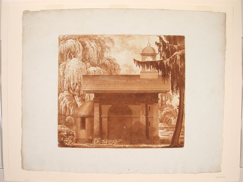
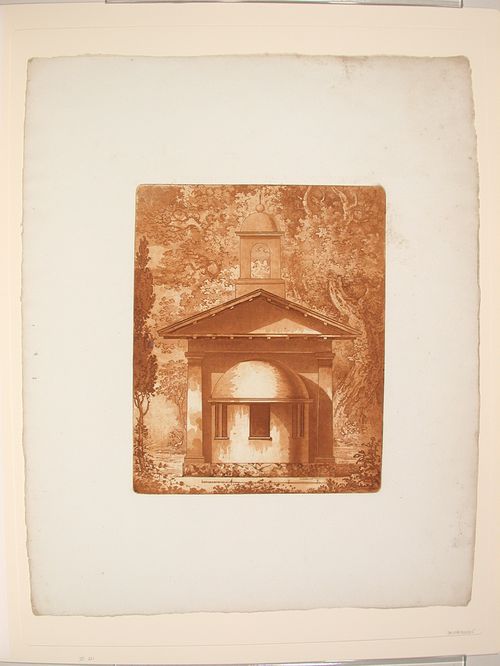
- Prints DR1987:0064 - DR1987:0069 are probably for a mausoleum and include 3 elevations, 2 sections and 1 plan. The mausoleum is almost square in plan with a protruding semidomed apse and a portico "in antis" consisting of two Tuscan engaged pillars supporting a thick architrave which runs around the exterior of the mausoleum. The structure is raised on a podium and has a gabled roof perched high above the main structure, surmounted by a cupola crowned with an orb and cross. On the interior, the barrel vaulted nave is separated from the apse by a rood-like screen pierced by three doors and by a Corinthian colonnade. The chancel and apse areas are slightly raised and are accessed by a flight of stairs. A spiral staircase on the left side of the narthex provides access to the gallery, upper level, and cupola. A tomb monument or sarcophagus, composed of a rectangular masonry slab surmounted by a vertical slab decorated with a recumbent female figure, is located at the centre of the lateral wall of the nave under the fanlight.
DR1987:0064
Description:
- Prints DR1987:0064 - DR1987:0069 are probably for a mausoleum and include 3 elevations, 2 sections and 1 plan. The mausoleum is almost square in plan with a protruding semidomed apse and a portico "in antis" consisting of two Tuscan engaged pillars supporting a thick architrave which runs around the exterior of the mausoleum. The structure is raised on a podium and has a gabled roof perched high above the main structure, surmounted by a cupola crowned with an orb and cross. On the interior, the barrel vaulted nave is separated from the apse by a rood-like screen pierced by three doors and by a Corinthian colonnade. The chancel and apse areas are slightly raised and are accessed by a flight of stairs. A spiral staircase on the left side of the narthex provides access to the gallery, upper level, and cupola. A tomb monument or sarcophagus, composed of a rectangular masonry slab surmounted by a vertical slab decorated with a recumbent female figure, is located at the centre of the lateral wall of the nave under the fanlight.
People:
Subject:
architecture
architecture
Date:
early 19th century
early 19th century
Title:
Side elevation of a mausoleum in a wooded setting
Actions:
DR1987:0064
Description:
- Prints DR1987:0064 - DR1987:0069 are probably for a mausoleum and include 3 elevations, 2 sections and 1 plan. The mausoleum is almost square in plan with a protruding semidomed apse and a portico "in antis" consisting of two Tuscan engaged pillars supporting a thick architrave which runs around the exterior of the mausoleum. The structure is raised on a podium and has a gabled roof perched high above the main structure, surmounted by a cupola crowned with an orb and cross. On the interior, the barrel vaulted nave is separated from the apse by a rood-like screen pierced by three doors and by a Corinthian colonnade. The chancel and apse areas are slightly raised and are accessed by a flight of stairs. A spiral staircase on the left side of the narthex provides access to the gallery, upper level, and cupola. A tomb monument or sarcophagus, composed of a rectangular masonry slab surmounted by a vertical slab decorated with a recumbent female figure, is located at the centre of the lateral wall of the nave under the fanlight.
Side elevation of a mausoleum in a wooded setting
Actions:
DR1987:0064
Description:
- Prints DR1987:0064 - DR1987:0069 are probably for a mausoleum and include 3 elevations, 2 sections and 1 plan. The mausoleum is almost square in plan with a protruding semidomed apse and a portico "in antis" consisting of two Tuscan engaged pillars supporting a thick architrave which runs around the exterior of the mausoleum. The structure is raised on a podium and has a gabled roof perched high above the main structure, surmounted by a cupola crowned with an orb and cross. On the interior, the barrel vaulted nave is separated from the apse by a rood-like screen pierced by three doors and by a Corinthian colonnade. The chancel and apse areas are slightly raised and are accessed by a flight of stairs. A spiral staircase on the left side of the narthex provides access to the gallery, upper level, and cupola. A tomb monument or sarcophagus, composed of a rectangular masonry slab surmounted by a vertical slab decorated with a recumbent female figure, is located at the centre of the lateral wall of the nave under the fanlight.
Form:
works of art
works of art
Date:
early 19th century
early 19th century
People:
Subject:
architecture
architecture
Form:
works of art
works of art
Actions:
Reference number:
DR1987:0065
Description:
- Prints DR1987:0064 - DR1987:0069 are probably for a mausoleum and include 3 elevations, 2 sections and 1 plan. The mausoleum is almost square in plan with a protruding semidomed apse and a portico "in antis" consisting of two Tuscan engaged pillars supporting a thick architrave which runs around the exterior of the mausoleum. The structure is raised on a podium and has a gabled roof perched high above the main structure, surmounted by a cupola crowned with an orb and cross. On the interior, the barrel vaulted nave is separated from the apse by a rood-like screen pierced by three doors and by a Corinthian colonnade. The chancel and apse areas are slightly raised and are accessed by a flight of stairs. A spiral staircase on the left side of the narthex provides access to the gallery, upper level, and cupola. A tomb monument or sarcophagus, composed of a rectangular masonry slab surmounted by a vertical slab decorated with a recumbent female figure, is located at the centre of the lateral wall of the nave under the fanlight.
DR1987:0065
Description:
- Prints DR1987:0064 - DR1987:0069 are probably for a mausoleum and include 3 elevations, 2 sections and 1 plan. The mausoleum is almost square in plan with a protruding semidomed apse and a portico "in antis" consisting of two Tuscan engaged pillars supporting a thick architrave which runs around the exterior of the mausoleum. The structure is raised on a podium and has a gabled roof perched high above the main structure, surmounted by a cupola crowned with an orb and cross. On the interior, the barrel vaulted nave is separated from the apse by a rood-like screen pierced by three doors and by a Corinthian colonnade. The chancel and apse areas are slightly raised and are accessed by a flight of stairs. A spiral staircase on the left side of the narthex provides access to the gallery, upper level, and cupola. A tomb monument or sarcophagus, composed of a rectangular masonry slab surmounted by a vertical slab decorated with a recumbent female figure, is located at the centre of the lateral wall of the nave under the fanlight.
People:
Subject:
architecture
architecture
Date:
early 19th century
early 19th century
Title:
Rear elevation of a mausoleum in a wooded setting
Actions:
DR1987:0065
Description:
- Prints DR1987:0064 - DR1987:0069 are probably for a mausoleum and include 3 elevations, 2 sections and 1 plan. The mausoleum is almost square in plan with a protruding semidomed apse and a portico "in antis" consisting of two Tuscan engaged pillars supporting a thick architrave which runs around the exterior of the mausoleum. The structure is raised on a podium and has a gabled roof perched high above the main structure, surmounted by a cupola crowned with an orb and cross. On the interior, the barrel vaulted nave is separated from the apse by a rood-like screen pierced by three doors and by a Corinthian colonnade. The chancel and apse areas are slightly raised and are accessed by a flight of stairs. A spiral staircase on the left side of the narthex provides access to the gallery, upper level, and cupola. A tomb monument or sarcophagus, composed of a rectangular masonry slab surmounted by a vertical slab decorated with a recumbent female figure, is located at the centre of the lateral wall of the nave under the fanlight.
Rear elevation of a mausoleum in a wooded setting
Actions:
DR1987:0065
Description:
- Prints DR1987:0064 - DR1987:0069 are probably for a mausoleum and include 3 elevations, 2 sections and 1 plan. The mausoleum is almost square in plan with a protruding semidomed apse and a portico "in antis" consisting of two Tuscan engaged pillars supporting a thick architrave which runs around the exterior of the mausoleum. The structure is raised on a podium and has a gabled roof perched high above the main structure, surmounted by a cupola crowned with an orb and cross. On the interior, the barrel vaulted nave is separated from the apse by a rood-like screen pierced by three doors and by a Corinthian colonnade. The chancel and apse areas are slightly raised and are accessed by a flight of stairs. A spiral staircase on the left side of the narthex provides access to the gallery, upper level, and cupola. A tomb monument or sarcophagus, composed of a rectangular masonry slab surmounted by a vertical slab decorated with a recumbent female figure, is located at the centre of the lateral wall of the nave under the fanlight.
Form:
works of art
works of art
Date:
early 19th century
early 19th century
People:
Subject:
architecture
architecture


