


11176 Results
Form:
drawings
drawings
Title:
Plans and elevations for the second phase, Music School and History Museum, Stuttgart, Germany
Plans and elevations for the second phase, Music School and History Museum, Stuttgart, Germany
Actions:
Reference number:
AP140.S2.SS1.D79.P94
Description:
Plans and elevations for the second phase of the Music School and for the History Museum, also site plans, floor plans, elevations, sections, perspectives and axonometrics, including for lobby and shop, for the theatre garden and theatre garden stairs and for proposals for a crossing over Konrad-Adenauer-Strasse.
AP140.S2.SS1.D79.P94
Description:
Plans and elevations for the second phase of the Music School and for the History Museum, also site plans, floor plans, elevations, sections, perspectives and axonometrics, including for lobby and shop, for the theatre garden and theatre garden stairs and for proposals for a crossing over Konrad-Adenauer-Strasse.
People:
Date:
circa 1985-2000
circa 1985-2000
Title:
Plans and elevations for the second phase, Music School and History Museum, Stuttgart, Germany
Actions:
AP140.S2.SS1.D79.P94
Description:
Plans and elevations for the second phase of the Music School and for the History Museum, also site plans, floor plans, elevations, sections, perspectives and axonometrics, including for lobby and shop, for the theatre garden and theatre garden stairs and for proposals for a crossing over Konrad-Adenauer-Strasse.
Plans and elevations for the second phase, Music School and History Museum, Stuttgart, Germany
Actions:
AP140.S2.SS1.D79.P94
Description:
Plans and elevations for the second phase of the Music School and for the History Museum, also site plans, floor plans, elevations, sections, perspectives and axonometrics, including for lobby and shop, for the theatre garden and theatre garden stairs and for proposals for a crossing over Konrad-Adenauer-Strasse.
Form:
drawings
drawings
Date:
circa 1985-2000
circa 1985-2000
People:
Form:
textual records
textual records
Actions:
Reference number:
ARCH256924
Description:
correspondence with Erickson / Massey, correspondence with customers, distributors. Client / designer agreement with Expo '67 and correspondence and photographs (plans and perspectives) concerning the Habitat unit #244 exhibit by Kripacz, specifications and drawings for Federal Investments Office Interiors (Erickson / Massey, 1968), vouchers, Cinova Furniture catalogues
ARCH256924
Description:
correspondence with Erickson / Massey, correspondence with customers, distributors. Client / designer agreement with Expo '67 and correspondence and photographs (plans and perspectives) concerning the Habitat unit #244 exhibit by Kripacz, specifications and drawings for Federal Investments Office Interiors (Erickson / Massey, 1968), vouchers, Cinova Furniture catalogues
People:
Date:
1963-1977
1963-1977
Title:
Correspondence with Erickson / Massey, correspondence with customers, distributors, agreements, specifications and suppliers catalogues
Actions:
ARCH256924
Description:
correspondence with Erickson / Massey, correspondence with customers, distributors. Client / designer agreement with Expo '67 and correspondence and photographs (plans and perspectives) concerning the Habitat unit #244 exhibit by Kripacz, specifications and drawings for Federal Investments Office Interiors (Erickson / Massey, 1968), vouchers, Cinova Furniture catalogues
Correspondence with Erickson / Massey, correspondence with customers, distributors, agreements, specifications and suppliers catalogues
Actions:
ARCH256924
Description:
correspondence with Erickson / Massey, correspondence with customers, distributors. Client / designer agreement with Expo '67 and correspondence and photographs (plans and perspectives) concerning the Habitat unit #244 exhibit by Kripacz, specifications and drawings for Federal Investments Office Interiors (Erickson / Massey, 1968), vouchers, Cinova Furniture catalogues
Form:
textual records
textual records
Date:
1963-1977
1963-1977
People:
Form:
drawings
Quantity:
15 presentation drawing(s)
drawings
Quantity:
15 presentation drawing(s)
Actions:
Reference number:
DR1995:0188:476-490
Description:
site plans, sections, diagrammatic plan showing access elements, exterior perspectives, layout plans, and axonometric site plan for Camden Town proposal, Mill Meads map, table layout for main activities, axonometric drawing of Fun Palace showing structure, and sketch plan and section with costing calculations
DR1995:0188:476-490
Description:
site plans, sections, diagrammatic plan showing access elements, exterior perspectives, layout plans, and axonometric site plan for Camden Town proposal, Mill Meads map, table layout for main activities, axonometric drawing of Fun Palace showing structure, and sketch plan and section with costing calculations
People:
Title:
Site plans, sections, diagrammatic plan showing access elements
Actions:
DR1995:0188:476-490
Description:
site plans, sections, diagrammatic plan showing access elements, exterior perspectives, layout plans, and axonometric site plan for Camden Town proposal, Mill Meads map, table layout for main activities, axonometric drawing of Fun Palace showing structure, and sketch plan and section with costing calculations
Site plans, sections, diagrammatic plan showing access elements
Actions:
DR1995:0188:476-490
Description:
site plans, sections, diagrammatic plan showing access elements, exterior perspectives, layout plans, and axonometric site plan for Camden Town proposal, Mill Meads map, table layout for main activities, axonometric drawing of Fun Palace showing structure, and sketch plan and section with costing calculations
Form:
drawings
Quantity:
15 presentation drawing(s)
drawings
Quantity:
15 presentation drawing(s)
People:
Form:
drawings
drawings
Reference number:
ARCH5455
Description:
Plan du sous-sol, élévation de la façade latérale nord, coupe longitudinale, perspectives et détails du portique principal, élévations et détails du campanile, demi-plans et coupes du chœur, coupes latérales de la nef avec détails des autels, élévation de l'orgue, coupe sur un escalier, plan partiel du site.
ARCH5455
Description:
Plan du sous-sol, élévation de la façade latérale nord, coupe longitudinale, perspectives et détails du portique principal, élévations et détails du campanile, demi-plans et coupes du chœur, coupes latérales de la nef avec détails des autels, élévation de l'orgue, coupe sur un escalier, plan partiel du site.
People:
Date:
circa 1925
circa 1925
Title:
Plans d'étage, élévations, coupes, et détails
Actions:
ARCH5455
Description:
Plan du sous-sol, élévation de la façade latérale nord, coupe longitudinale, perspectives et détails du portique principal, élévations et détails du campanile, demi-plans et coupes du chœur, coupes latérales de la nef avec détails des autels, élévation de l'orgue, coupe sur un escalier, plan partiel du site.
Plans d'étage, élévations, coupes, et détails
Actions:
ARCH5455
Description:
Plan du sous-sol, élévation de la façade latérale nord, coupe longitudinale, perspectives et détails du portique principal, élévations et détails du campanile, demi-plans et coupes du chœur, coupes latérales de la nef avec détails des autels, élévation de l'orgue, coupe sur un escalier, plan partiel du site.
Form:
drawings
drawings
Date:
circa 1925
circa 1925
People:
Actions:
Reference number:
ARCH402203
Description:
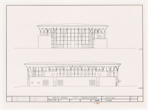
Most of the album contains computer renderings and wireframe drawings for the roof of the Galaxy Toyama Gymnasium. There is also a group of printouts or photocopies of plans related to a photoelasticity experiment. There are views, dated 2012, of a model for the roof. Also included are photocopies or printouts of plans, elevations, a section and perspectives.
ARCH402203
Description:
Most of the album contains computer renderings and wireframe drawings for the roof of the Galaxy Toyama Gymnasium. There is also a group of printouts or photocopies of plans related to a photoelasticity experiment. There are views, dated 2012, of a model for the roof. Also included are photocopies or printouts of plans, elevations, a section and perspectives.
People:
Date:
between 1990 and 2012?
between 1990 and 2012?
Title:
Album containing plans and views related to Galaxy Toyama Gymnasium, Imizu, Japan
Actions:
ARCH402203
Description:
Most of the album contains computer renderings and wireframe drawings for the roof of the Galaxy Toyama Gymnasium. There is also a group of printouts or photocopies of plans related to a photoelasticity experiment. There are views, dated 2012, of a model for the roof. Also included are photocopies or printouts of plans, elevations, a section and perspectives.
Album containing plans and views related to Galaxy Toyama Gymnasium, Imizu, Japan
Actions:
ARCH402203
Description:
Most of the album contains computer renderings and wireframe drawings for the roof of the Galaxy Toyama Gymnasium. There is also a group of printouts or photocopies of plans related to a photoelasticity experiment. There are views, dated 2012, of a model for the roof. Also included are photocopies or printouts of plans, elevations, a section and perspectives.
Date:
between 1990 and 2012?
between 1990 and 2012?
People:
Level of archival description:
Project
Project
Reference number:
AP056.S1.2000.PR08
Description:
This project series documents buildings for Concordia University's downtown campus in Montréal from 2000-2009. The office identified the project number as 0004. This project eventually became known as Le Quartier Concordia. This project was the winning submission of an architectural competition by Kuwabara Payne McKenna Blumberg Architects, in joint-venture with Fichten Soiferman et Associés Architectes, to design an integrated, vertical campus to revitalize and reinvent the University. This project consisted of three interconnected high-rise buildings on either side of Montreal's Guy Street, below De Maisonneuve Boulevard, to rehouse three important faculties: Visual Arts, Engineering and Computer Science, and the John Molson School of Business. These three buildings had glazed curtain wall exteriors with copper-coloured metal lines that created visual consistency inside and outside of all three buildings. Large art installations were also included on the façades. Triple-height atriums on the ground floors of the Engineering Building and the John Molson building added welcoming, public areas to the campus, and connected pedestrians to the Guy-Concordia metro station below. The tops of these two buildings featured massive north-south canopies that pointed from Montreal's Mont Royal down to the St. Lawrence River. The shorter Visual Arts building was directly connected to the Engineering building and today they are known together as the EV Building. The building interiors, comprised largely of stone tiles and concrete, featured large, multi-storey spiral staircases in a nod to the famous exterior spiral stairs of Montreal homes.[1] The Engineering and Visual Arts buildings were completed in 2005 and the John Molson building in 2009. Recladding of the exterior of another campus building to match these was completed in 2011.[2] It should be noted that these project materials were donated to the CCA part way through the project's realization. The project is recorded through drawings and textual records dating from 2000-2003. The drawings are mostly originals but reprographic copies and printouts of CAD drawings are also included. The drawings consist of sketches, digital renderings, plans, elevations, sections, perspectives, details and construction drawings. The textual records are arranged within the drawings and consist of research. [1]Contributions from Phyllis Lambert et al., The Architecture of Kuwabara, Payne, McKenna, Blumberg (Boston, MA: Birkhäuser-Publishers for Architecture, 2004), 180. [2]"Le Quartier Concordia." KPMB. Accessed July 11, 2019. http://www.kpmb.com/project/concordia-university-john-molson-school-of-business/
AP056.S1.2000.PR08
Description:
This project series documents buildings for Concordia University's downtown campus in Montréal from 2000-2009. The office identified the project number as 0004. This project eventually became known as Le Quartier Concordia. This project was the winning submission of an architectural competition by Kuwabara Payne McKenna Blumberg Architects, in joint-venture with Fichten Soiferman et Associés Architectes, to design an integrated, vertical campus to revitalize and reinvent the University. This project consisted of three interconnected high-rise buildings on either side of Montreal's Guy Street, below De Maisonneuve Boulevard, to rehouse three important faculties: Visual Arts, Engineering and Computer Science, and the John Molson School of Business. These three buildings had glazed curtain wall exteriors with copper-coloured metal lines that created visual consistency inside and outside of all three buildings. Large art installations were also included on the façades. Triple-height atriums on the ground floors of the Engineering Building and the John Molson building added welcoming, public areas to the campus, and connected pedestrians to the Guy-Concordia metro station below. The tops of these two buildings featured massive north-south canopies that pointed from Montreal's Mont Royal down to the St. Lawrence River. The shorter Visual Arts building was directly connected to the Engineering building and today they are known together as the EV Building. The building interiors, comprised largely of stone tiles and concrete, featured large, multi-storey spiral staircases in a nod to the famous exterior spiral stairs of Montreal homes.[1] The Engineering and Visual Arts buildings were completed in 2005 and the John Molson building in 2009. Recladding of the exterior of another campus building to match these was completed in 2011.[2] It should be noted that these project materials were donated to the CCA part way through the project's realization. The project is recorded through drawings and textual records dating from 2000-2003. The drawings are mostly originals but reprographic copies and printouts of CAD drawings are also included. The drawings consist of sketches, digital renderings, plans, elevations, sections, perspectives, details and construction drawings. The textual records are arranged within the drawings and consist of research. [1]Contributions from Phyllis Lambert et al., The Architecture of Kuwabara, Payne, McKenna, Blumberg (Boston, MA: Birkhäuser-Publishers for Architecture, 2004), 180. [2]"Le Quartier Concordia." KPMB. Accessed July 11, 2019. http://www.kpmb.com/project/concordia-university-john-molson-school-of-business/
People:
Date:
2000-2003
2000-2003
Title:
Concordia University, Montréal (2000-2009)
Actions:
AP056.S1.2000.PR08
Description:
This project series documents buildings for Concordia University's downtown campus in Montréal from 2000-2009. The office identified the project number as 0004. This project eventually became known as Le Quartier Concordia. This project was the winning submission of an architectural competition by Kuwabara Payne McKenna Blumberg Architects, in joint-venture with Fichten Soiferman et Associés Architectes, to design an integrated, vertical campus to revitalize and reinvent the University. This project consisted of three interconnected high-rise buildings on either side of Montreal's Guy Street, below De Maisonneuve Boulevard, to rehouse three important faculties: Visual Arts, Engineering and Computer Science, and the John Molson School of Business. These three buildings had glazed curtain wall exteriors with copper-coloured metal lines that created visual consistency inside and outside of all three buildings. Large art installations were also included on the façades. Triple-height atriums on the ground floors of the Engineering Building and the John Molson building added welcoming, public areas to the campus, and connected pedestrians to the Guy-Concordia metro station below. The tops of these two buildings featured massive north-south canopies that pointed from Montreal's Mont Royal down to the St. Lawrence River. The shorter Visual Arts building was directly connected to the Engineering building and today they are known together as the EV Building. The building interiors, comprised largely of stone tiles and concrete, featured large, multi-storey spiral staircases in a nod to the famous exterior spiral stairs of Montreal homes.[1] The Engineering and Visual Arts buildings were completed in 2005 and the John Molson building in 2009. Recladding of the exterior of another campus building to match these was completed in 2011.[2] It should be noted that these project materials were donated to the CCA part way through the project's realization. The project is recorded through drawings and textual records dating from 2000-2003. The drawings are mostly originals but reprographic copies and printouts of CAD drawings are also included. The drawings consist of sketches, digital renderings, plans, elevations, sections, perspectives, details and construction drawings. The textual records are arranged within the drawings and consist of research. [1]Contributions from Phyllis Lambert et al., The Architecture of Kuwabara, Payne, McKenna, Blumberg (Boston, MA: Birkhäuser-Publishers for Architecture, 2004), 180. [2]"Le Quartier Concordia." KPMB. Accessed July 11, 2019. http://www.kpmb.com/project/concordia-university-john-molson-school-of-business/
Concordia University, Montréal (2000-2009)
Actions:
AP056.S1.2000.PR08
Description:
This project series documents buildings for Concordia University's downtown campus in Montréal from 2000-2009. The office identified the project number as 0004. This project eventually became known as Le Quartier Concordia. This project was the winning submission of an architectural competition by Kuwabara Payne McKenna Blumberg Architects, in joint-venture with Fichten Soiferman et Associés Architectes, to design an integrated, vertical campus to revitalize and reinvent the University. This project consisted of three interconnected high-rise buildings on either side of Montreal's Guy Street, below De Maisonneuve Boulevard, to rehouse three important faculties: Visual Arts, Engineering and Computer Science, and the John Molson School of Business. These three buildings had glazed curtain wall exteriors with copper-coloured metal lines that created visual consistency inside and outside of all three buildings. Large art installations were also included on the façades. Triple-height atriums on the ground floors of the Engineering Building and the John Molson building added welcoming, public areas to the campus, and connected pedestrians to the Guy-Concordia metro station below. The tops of these two buildings featured massive north-south canopies that pointed from Montreal's Mont Royal down to the St. Lawrence River. The shorter Visual Arts building was directly connected to the Engineering building and today they are known together as the EV Building. The building interiors, comprised largely of stone tiles and concrete, featured large, multi-storey spiral staircases in a nod to the famous exterior spiral stairs of Montreal homes.[1] The Engineering and Visual Arts buildings were completed in 2005 and the John Molson building in 2009. Recladding of the exterior of another campus building to match these was completed in 2011.[2] It should be noted that these project materials were donated to the CCA part way through the project's realization. The project is recorded through drawings and textual records dating from 2000-2003. The drawings are mostly originals but reprographic copies and printouts of CAD drawings are also included. The drawings consist of sketches, digital renderings, plans, elevations, sections, perspectives, details and construction drawings. The textual records are arranged within the drawings and consist of research. [1]Contributions from Phyllis Lambert et al., The Architecture of Kuwabara, Payne, McKenna, Blumberg (Boston, MA: Birkhäuser-Publishers for Architecture, 2004), 180. [2]"Le Quartier Concordia." KPMB. Accessed July 11, 2019. http://www.kpmb.com/project/concordia-university-john-molson-school-of-business/
Level of archival description:
Project
Project
Date:
2000-2003
2000-2003
People:
Form:
drawings
drawings
Actions:
Reference number:
DR1974:0002:035:001-034
Description:
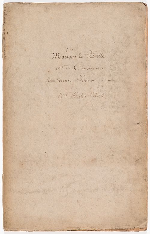
- This album consists primarily of preliminary and design development drawings for diverse projects - mostly domestic - from the early years of Hubert Rohault de Fleury's career. Some of the fifteen more finished drawings in wash and watercolour are probably presentation drawings. Many of the drawings are inscribed with illegible or partially legible notations concerning the project's location, client, date and other particulars. There are seven drawings for a house on rue d'Aguesseau, Paris, probably the Rohault de Fleury family residence (DR1974:0002:035:002 - DR1974:OOO2:035:006 R/V) and several drawings for a house for Rohault de Fleury's uncle on rue Saint-Romain, Paris (DR1974:0002:035:012 V). Several drawings are after plates published in Durand's "Précis des Leçons d'architecture données à l'école Royale Polytechnique (1802-1805)": plans on drawings DR1974:0002:035:011 V, DR1974:0002:035:012 R are adapted from plate 25 and combined with façades designed by Rohault de Fleury, and drawing DR1974:0002:035:013 R is based on an engraving by Charles-Pierre-Joseph Normand (pl. 23) of Hôtel Lathuille in Paris which was designed by Jean-Nicolas-Louis Durand (1788). Perspective sketches and plans are included for the restoration of a château in Rocheux [?] for M. le Trône (DR1974:0002:035:017 R) and for the renovation for the house at Domaine de la Vallée (DR1974:0002:035:020). The drawing for a country villa was executed in 1804, while Rohault de Fleury was in Rome studying at the French Academy (DR1974:0002:035:021 R). The conceptual drawing of a small "orchestre" and the elevations of a gallery and portico gate are inscribed "Jardin du Frascati", and are perhaps travel sketches or projects executed while Rohault de Fleury was in Rome (DR1974:0002:035:032 V, DR1974:002:035:033 R, and DR1974:0002:035:034). Also included in the album are two plans for part of the Passage du saumon in Paris (DR1974:0002:035:014 R), a plan, elevation and section for a rustic pavilion for M. Abrial (DR1974:0002:035:024 V), a plan for a shepherd's house in St. Cueufin [?] (DR1974:0002:035:021 V), a house for M. Quitton in Paris (DR1974:0002:035:026 - DR1974:0002:035:027), a section, elevation and plan for a sheepfold (DR1974:0002:035:033 V) and a perspective for a rustic cabin (DR1974:0002:035:034). The album also contains a number of drawings for Empire-style interior design projects: interior wall elevations, furniture drawings, and plans, elevations and perspectives for a bed alcove.
DR1974:0002:035:001-034
Description:
- This album consists primarily of preliminary and design development drawings for diverse projects - mostly domestic - from the early years of Hubert Rohault de Fleury's career. Some of the fifteen more finished drawings in wash and watercolour are probably presentation drawings. Many of the drawings are inscribed with illegible or partially legible notations concerning the project's location, client, date and other particulars. There are seven drawings for a house on rue d'Aguesseau, Paris, probably the Rohault de Fleury family residence (DR1974:0002:035:002 - DR1974:OOO2:035:006 R/V) and several drawings for a house for Rohault de Fleury's uncle on rue Saint-Romain, Paris (DR1974:0002:035:012 V). Several drawings are after plates published in Durand's "Précis des Leçons d'architecture données à l'école Royale Polytechnique (1802-1805)": plans on drawings DR1974:0002:035:011 V, DR1974:0002:035:012 R are adapted from plate 25 and combined with façades designed by Rohault de Fleury, and drawing DR1974:0002:035:013 R is based on an engraving by Charles-Pierre-Joseph Normand (pl. 23) of Hôtel Lathuille in Paris which was designed by Jean-Nicolas-Louis Durand (1788). Perspective sketches and plans are included for the restoration of a château in Rocheux [?] for M. le Trône (DR1974:0002:035:017 R) and for the renovation for the house at Domaine de la Vallée (DR1974:0002:035:020). The drawing for a country villa was executed in 1804, while Rohault de Fleury was in Rome studying at the French Academy (DR1974:0002:035:021 R). The conceptual drawing of a small "orchestre" and the elevations of a gallery and portico gate are inscribed "Jardin du Frascati", and are perhaps travel sketches or projects executed while Rohault de Fleury was in Rome (DR1974:0002:035:032 V, DR1974:002:035:033 R, and DR1974:0002:035:034). Also included in the album are two plans for part of the Passage du saumon in Paris (DR1974:0002:035:014 R), a plan, elevation and section for a rustic pavilion for M. Abrial (DR1974:0002:035:024 V), a plan for a shepherd's house in St. Cueufin [?] (DR1974:0002:035:021 V), a house for M. Quitton in Paris (DR1974:0002:035:026 - DR1974:0002:035:027), a section, elevation and plan for a sheepfold (DR1974:0002:035:033 V) and a perspective for a rustic cabin (DR1974:0002:035:034). The album also contains a number of drawings for Empire-style interior design projects: interior wall elevations, furniture drawings, and plans, elevations and perspectives for a bed alcove.
People:
Subject:
architecture, landscape architecture, interior design
architecture, landscape architecture, interior design
Date:
early 19th century
early 19th century
Title:
Album of drawings, mostly for French town and country houses, including some drawings for interiors and furniture, and one drawing for the Passage du saumon, Paris
Actions:
DR1974:0002:035:001-034
Description:
- This album consists primarily of preliminary and design development drawings for diverse projects - mostly domestic - from the early years of Hubert Rohault de Fleury's career. Some of the fifteen more finished drawings in wash and watercolour are probably presentation drawings. Many of the drawings are inscribed with illegible or partially legible notations concerning the project's location, client, date and other particulars. There are seven drawings for a house on rue d'Aguesseau, Paris, probably the Rohault de Fleury family residence (DR1974:0002:035:002 - DR1974:OOO2:035:006 R/V) and several drawings for a house for Rohault de Fleury's uncle on rue Saint-Romain, Paris (DR1974:0002:035:012 V). Several drawings are after plates published in Durand's "Précis des Leçons d'architecture données à l'école Royale Polytechnique (1802-1805)": plans on drawings DR1974:0002:035:011 V, DR1974:0002:035:012 R are adapted from plate 25 and combined with façades designed by Rohault de Fleury, and drawing DR1974:0002:035:013 R is based on an engraving by Charles-Pierre-Joseph Normand (pl. 23) of Hôtel Lathuille in Paris which was designed by Jean-Nicolas-Louis Durand (1788). Perspective sketches and plans are included for the restoration of a château in Rocheux [?] for M. le Trône (DR1974:0002:035:017 R) and for the renovation for the house at Domaine de la Vallée (DR1974:0002:035:020). The drawing for a country villa was executed in 1804, while Rohault de Fleury was in Rome studying at the French Academy (DR1974:0002:035:021 R). The conceptual drawing of a small "orchestre" and the elevations of a gallery and portico gate are inscribed "Jardin du Frascati", and are perhaps travel sketches or projects executed while Rohault de Fleury was in Rome (DR1974:0002:035:032 V, DR1974:002:035:033 R, and DR1974:0002:035:034). Also included in the album are two plans for part of the Passage du saumon in Paris (DR1974:0002:035:014 R), a plan, elevation and section for a rustic pavilion for M. Abrial (DR1974:0002:035:024 V), a plan for a shepherd's house in St. Cueufin [?] (DR1974:0002:035:021 V), a house for M. Quitton in Paris (DR1974:0002:035:026 - DR1974:0002:035:027), a section, elevation and plan for a sheepfold (DR1974:0002:035:033 V) and a perspective for a rustic cabin (DR1974:0002:035:034). The album also contains a number of drawings for Empire-style interior design projects: interior wall elevations, furniture drawings, and plans, elevations and perspectives for a bed alcove.
Album of drawings, mostly for French town and country houses, including some drawings for interiors and furniture, and one drawing for the Passage du saumon, Paris
Actions:
DR1974:0002:035:001-034
Description:
- This album consists primarily of preliminary and design development drawings for diverse projects - mostly domestic - from the early years of Hubert Rohault de Fleury's career. Some of the fifteen more finished drawings in wash and watercolour are probably presentation drawings. Many of the drawings are inscribed with illegible or partially legible notations concerning the project's location, client, date and other particulars. There are seven drawings for a house on rue d'Aguesseau, Paris, probably the Rohault de Fleury family residence (DR1974:0002:035:002 - DR1974:OOO2:035:006 R/V) and several drawings for a house for Rohault de Fleury's uncle on rue Saint-Romain, Paris (DR1974:0002:035:012 V). Several drawings are after plates published in Durand's "Précis des Leçons d'architecture données à l'école Royale Polytechnique (1802-1805)": plans on drawings DR1974:0002:035:011 V, DR1974:0002:035:012 R are adapted from plate 25 and combined with façades designed by Rohault de Fleury, and drawing DR1974:0002:035:013 R is based on an engraving by Charles-Pierre-Joseph Normand (pl. 23) of Hôtel Lathuille in Paris which was designed by Jean-Nicolas-Louis Durand (1788). Perspective sketches and plans are included for the restoration of a château in Rocheux [?] for M. le Trône (DR1974:0002:035:017 R) and for the renovation for the house at Domaine de la Vallée (DR1974:0002:035:020). The drawing for a country villa was executed in 1804, while Rohault de Fleury was in Rome studying at the French Academy (DR1974:0002:035:021 R). The conceptual drawing of a small "orchestre" and the elevations of a gallery and portico gate are inscribed "Jardin du Frascati", and are perhaps travel sketches or projects executed while Rohault de Fleury was in Rome (DR1974:0002:035:032 V, DR1974:002:035:033 R, and DR1974:0002:035:034). Also included in the album are two plans for part of the Passage du saumon in Paris (DR1974:0002:035:014 R), a plan, elevation and section for a rustic pavilion for M. Abrial (DR1974:0002:035:024 V), a plan for a shepherd's house in St. Cueufin [?] (DR1974:0002:035:021 V), a house for M. Quitton in Paris (DR1974:0002:035:026 - DR1974:0002:035:027), a section, elevation and plan for a sheepfold (DR1974:0002:035:033 V) and a perspective for a rustic cabin (DR1974:0002:035:034). The album also contains a number of drawings for Empire-style interior design projects: interior wall elevations, furniture drawings, and plans, elevations and perspectives for a bed alcove.
Form:
drawings
drawings
Date:
early 19th century
early 19th century
People:
Subject:
architecture, landscape architecture, interior design
architecture, landscape architecture, interior design
Form:
drawings
drawings
Actions:
Reference number:
DR2004:0703
Description:
site plans, sketches, some with annotations, reference drawings, sections, perspectives, plans, captions, possibly presentation drawings, diagrams, schedules, views of site, drawings from the second Strate project, consultant's drawings, maps, measured sketches, notes, clippings, presentation panel layout sketches, overlays, calculations, proposal document, and axonometric
DR2004:0703
Description:
site plans, sketches, some with annotations, reference drawings, sections, perspectives, plans, captions, possibly presentation drawings, diagrams, schedules, views of site, drawings from the second Strate project, consultant's drawings, maps, measured sketches, notes, clippings, presentation panel layout sketches, overlays, calculations, proposal document, and axonometric
People:
Title:
Site plans, sketches, some with annotations, reference drawings
Actions:
DR2004:0703
Description:
site plans, sketches, some with annotations, reference drawings, sections, perspectives, plans, captions, possibly presentation drawings, diagrams, schedules, views of site, drawings from the second Strate project, consultant's drawings, maps, measured sketches, notes, clippings, presentation panel layout sketches, overlays, calculations, proposal document, and axonometric
Site plans, sketches, some with annotations, reference drawings
Actions:
DR2004:0703
Description:
site plans, sketches, some with annotations, reference drawings, sections, perspectives, plans, captions, possibly presentation drawings, diagrams, schedules, views of site, drawings from the second Strate project, consultant's drawings, maps, measured sketches, notes, clippings, presentation panel layout sketches, overlays, calculations, proposal document, and axonometric
Form:
drawings
drawings
People:
Form:
textual records
textual records
Reference number:
DR1995:0295:096-096
Description:
clippings, correspondence, photographs, publications, invitations, sketches (some with annotations, details, design development drawings, elevations, sections, plans, consultant's structural drawings from the Generator project, axonometrics, perspectives, and measured sketches), notes, press releases, memorandums, architect's statements, programmes, captions, drawings, text, drawing list, and book cover
DR1995:0295:096-096
Description:
clippings, correspondence, photographs, publications, invitations, sketches (some with annotations, details, design development drawings, elevations, sections, plans, consultant's structural drawings from the Generator project, axonometrics, perspectives, and measured sketches), notes, press releases, memorandums, architect's statements, programmes, captions, drawings, text, drawing list, and book cover
People:
Title:
Box of drawings and project documentation
Actions:
DR1995:0295:096-096
Description:
clippings, correspondence, photographs, publications, invitations, sketches (some with annotations, details, design development drawings, elevations, sections, plans, consultant's structural drawings from the Generator project, axonometrics, perspectives, and measured sketches), notes, press releases, memorandums, architect's statements, programmes, captions, drawings, text, drawing list, and book cover
Box of drawings and project documentation
Actions:
DR1995:0295:096-096
Description:
clippings, correspondence, photographs, publications, invitations, sketches (some with annotations, details, design development drawings, elevations, sections, plans, consultant's structural drawings from the Generator project, axonometrics, perspectives, and measured sketches), notes, press releases, memorandums, architect's statements, programmes, captions, drawings, text, drawing list, and book cover
Form:
textual records
textual records
People:
Level of archival description:
Project
Project
Reference number:
AP143.S4.D65
Description:
File documents the unexecuted project for the University Art Museum, Long Beach, California. Material in this file was produced between 1986 and 1988. California State University, Long Beach (CSULB), commissioned Eisenman/Robertson Architects to design an art museum adjacent to the main campus entrance. The 67,500-square-foot building was to comprise four galleries, a black-box theater, an auditorium, a cafe, conference rooms, a library, offices, preparation spaces, and storage vaults. The project, sited on a 23-acre arboretum, included landscaping; terraced sculpture courtyards, botanical gardens, and a two-acre pond. Eisenman linked the northern and southern parts of the arboretum by an elevated public walkway through the museum. Sets of drawings were presented on 8 and 30 April, 2 June, and 5 Aug. In the first design phase Eisenman explores the cartographic figures which form the basis of his artificial excavation when superposed: a series of sketches establishes the analogical relationships which fix the relative scales of the plans and produce the superpositions; another series contextualizes the superposed figures by placing them within the museum site (DR1987:0859:087-090). The second phase concerns the building; the working model shows the building carved out of a square pit, from which spring an oil derrick and a reconstruction of a recreational pier (Rainbow Pier, 1920s) used here as circulatory bridge (DR1987:0859:160). In the third phase the architect systematizes his archeological procedure by using five significant cartographic dates - 1849, 1889, 1949, 1989, 2049 - each corresponding to a specific superposition (see DR1987:0859:274-277). In the fourth phase, Eisenman simplifies the superposition of 2049 to a few iconic colour-coded forms: ranch (green), ranch house (blue), campus site (red), and water forms (river and pond) (gold). Material for the fourth phase includes three relief models, four presentation drawings, and a model (property of the CSULB) (relief models: DR1987:0859:001-003; drawings: DR1987:0859:004-008). Eisenman "inhabits" his artifical archeology by detailed planning of interior spaces, and gives substance to the cartographic traces in a series of sketch sections, perspectives, and working models. Working models reveal how the central "canal" area gradually became the museum's access point (DR1987:0859:484-490); the museum, galleries, offices, and preparation areas are on one side of this deep cut, while the cafeteria and black-box theater are on the other. The upper level was to house offices, meeting rooms, and the library. File contains audiovisual material, conceptual drawings, design development drawings, presentation drawings, reference drawings, working drawings, photographic materials, and textual records.
AP143.S4.D65
Description:
File documents the unexecuted project for the University Art Museum, Long Beach, California. Material in this file was produced between 1986 and 1988. California State University, Long Beach (CSULB), commissioned Eisenman/Robertson Architects to design an art museum adjacent to the main campus entrance. The 67,500-square-foot building was to comprise four galleries, a black-box theater, an auditorium, a cafe, conference rooms, a library, offices, preparation spaces, and storage vaults. The project, sited on a 23-acre arboretum, included landscaping; terraced sculpture courtyards, botanical gardens, and a two-acre pond. Eisenman linked the northern and southern parts of the arboretum by an elevated public walkway through the museum. Sets of drawings were presented on 8 and 30 April, 2 June, and 5 Aug. In the first design phase Eisenman explores the cartographic figures which form the basis of his artificial excavation when superposed: a series of sketches establishes the analogical relationships which fix the relative scales of the plans and produce the superpositions; another series contextualizes the superposed figures by placing them within the museum site (DR1987:0859:087-090). The second phase concerns the building; the working model shows the building carved out of a square pit, from which spring an oil derrick and a reconstruction of a recreational pier (Rainbow Pier, 1920s) used here as circulatory bridge (DR1987:0859:160). In the third phase the architect systematizes his archeological procedure by using five significant cartographic dates - 1849, 1889, 1949, 1989, 2049 - each corresponding to a specific superposition (see DR1987:0859:274-277). In the fourth phase, Eisenman simplifies the superposition of 2049 to a few iconic colour-coded forms: ranch (green), ranch house (blue), campus site (red), and water forms (river and pond) (gold). Material for the fourth phase includes three relief models, four presentation drawings, and a model (property of the CSULB) (relief models: DR1987:0859:001-003; drawings: DR1987:0859:004-008). Eisenman "inhabits" his artifical archeology by detailed planning of interior spaces, and gives substance to the cartographic traces in a series of sketch sections, perspectives, and working models. Working models reveal how the central "canal" area gradually became the museum's access point (DR1987:0859:484-490); the museum, galleries, offices, and preparation areas are on one side of this deep cut, while the cafeteria and black-box theater are on the other. The upper level was to house offices, meeting rooms, and the library. File contains audiovisual material, conceptual drawings, design development drawings, presentation drawings, reference drawings, working drawings, photographic materials, and textual records.
People:
Date:
1986-1988
1986-1988
Title:
University Art Museum
Actions:
AP143.S4.D65
Description:
File documents the unexecuted project for the University Art Museum, Long Beach, California. Material in this file was produced between 1986 and 1988. California State University, Long Beach (CSULB), commissioned Eisenman/Robertson Architects to design an art museum adjacent to the main campus entrance. The 67,500-square-foot building was to comprise four galleries, a black-box theater, an auditorium, a cafe, conference rooms, a library, offices, preparation spaces, and storage vaults. The project, sited on a 23-acre arboretum, included landscaping; terraced sculpture courtyards, botanical gardens, and a two-acre pond. Eisenman linked the northern and southern parts of the arboretum by an elevated public walkway through the museum. Sets of drawings were presented on 8 and 30 April, 2 June, and 5 Aug. In the first design phase Eisenman explores the cartographic figures which form the basis of his artificial excavation when superposed: a series of sketches establishes the analogical relationships which fix the relative scales of the plans and produce the superpositions; another series contextualizes the superposed figures by placing them within the museum site (DR1987:0859:087-090). The second phase concerns the building; the working model shows the building carved out of a square pit, from which spring an oil derrick and a reconstruction of a recreational pier (Rainbow Pier, 1920s) used here as circulatory bridge (DR1987:0859:160). In the third phase the architect systematizes his archeological procedure by using five significant cartographic dates - 1849, 1889, 1949, 1989, 2049 - each corresponding to a specific superposition (see DR1987:0859:274-277). In the fourth phase, Eisenman simplifies the superposition of 2049 to a few iconic colour-coded forms: ranch (green), ranch house (blue), campus site (red), and water forms (river and pond) (gold). Material for the fourth phase includes three relief models, four presentation drawings, and a model (property of the CSULB) (relief models: DR1987:0859:001-003; drawings: DR1987:0859:004-008). Eisenman "inhabits" his artifical archeology by detailed planning of interior spaces, and gives substance to the cartographic traces in a series of sketch sections, perspectives, and working models. Working models reveal how the central "canal" area gradually became the museum's access point (DR1987:0859:484-490); the museum, galleries, offices, and preparation areas are on one side of this deep cut, while the cafeteria and black-box theater are on the other. The upper level was to house offices, meeting rooms, and the library. File contains audiovisual material, conceptual drawings, design development drawings, presentation drawings, reference drawings, working drawings, photographic materials, and textual records.
University Art Museum
Actions:
AP143.S4.D65
Description:
File documents the unexecuted project for the University Art Museum, Long Beach, California. Material in this file was produced between 1986 and 1988. California State University, Long Beach (CSULB), commissioned Eisenman/Robertson Architects to design an art museum adjacent to the main campus entrance. The 67,500-square-foot building was to comprise four galleries, a black-box theater, an auditorium, a cafe, conference rooms, a library, offices, preparation spaces, and storage vaults. The project, sited on a 23-acre arboretum, included landscaping; terraced sculpture courtyards, botanical gardens, and a two-acre pond. Eisenman linked the northern and southern parts of the arboretum by an elevated public walkway through the museum. Sets of drawings were presented on 8 and 30 April, 2 June, and 5 Aug. In the first design phase Eisenman explores the cartographic figures which form the basis of his artificial excavation when superposed: a series of sketches establishes the analogical relationships which fix the relative scales of the plans and produce the superpositions; another series contextualizes the superposed figures by placing them within the museum site (DR1987:0859:087-090). The second phase concerns the building; the working model shows the building carved out of a square pit, from which spring an oil derrick and a reconstruction of a recreational pier (Rainbow Pier, 1920s) used here as circulatory bridge (DR1987:0859:160). In the third phase the architect systematizes his archeological procedure by using five significant cartographic dates - 1849, 1889, 1949, 1989, 2049 - each corresponding to a specific superposition (see DR1987:0859:274-277). In the fourth phase, Eisenman simplifies the superposition of 2049 to a few iconic colour-coded forms: ranch (green), ranch house (blue), campus site (red), and water forms (river and pond) (gold). Material for the fourth phase includes three relief models, four presentation drawings, and a model (property of the CSULB) (relief models: DR1987:0859:001-003; drawings: DR1987:0859:004-008). Eisenman "inhabits" his artifical archeology by detailed planning of interior spaces, and gives substance to the cartographic traces in a series of sketch sections, perspectives, and working models. Working models reveal how the central "canal" area gradually became the museum's access point (DR1987:0859:484-490); the museum, galleries, offices, and preparation areas are on one side of this deep cut, while the cafeteria and black-box theater are on the other. The upper level was to house offices, meeting rooms, and the library. File contains audiovisual material, conceptual drawings, design development drawings, presentation drawings, reference drawings, working drawings, photographic materials, and textual records.
Level of archival description:
File 65
File 65
Date:
1986-1988
1986-1988
People:


