44148 Résultats
Classification:
événements
événements
Titre:
Le rôle élargi: SITU
Le rôle élargi: SITU
Actions:
Description:
Bradley Samuels présente le travail récent de SITU Research et le rôle joué par la recherche au sein de la pratique de SITU dans son ensemble. Une série d’études de cas sera présentée, explorant le rôle élargi de la pratique architecturale et spatiale à travers un éventail de domaines, des droits humains à la politique publique, de la science de la terre au design(...)
Bradley Samuels présente le travail récent de SITU Research et le rôle joué par la recherche au sein de la pratique de SITU dans son ensemble. Une série d’études de cas sera présentée, explorant le rôle élargi de la pratique architecturale et spatiale à travers un éventail de domaines, des droits humains à la politique publique, de la science de la terre au design(...)
Localisation:
Théâtre Paul-Desmarais
Théâtre Paul-Desmarais
Date:
14 janvier 2016
14 janvier 2016
Titre:
Le rôle élargi: SITU
Actions:
Description:
Bradley Samuels présente le travail récent de SITU Research et le rôle joué par la recherche au sein de la pratique de SITU dans son ensemble. Une série d’études de cas sera présentée, explorant le rôle élargi de la pratique architecturale et spatiale à travers un éventail de domaines, des droits humains à la politique publique, de la science de la terre au design(...)
Classification:
événements
événements
Date:
14 janvier 2016
14 janvier 2016
Localisation:
Théâtre Paul-Desmarais
Théâtre Paul-Desmarais
Classification:
photographies
photographies

Numéro de référence:
ARCH402406
Description:
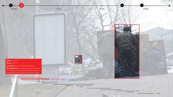
Possibly a construction worker.
ARCH402406
Description:
Possibly a construction worker.
Personnes et institutions:
Date:
between 1951 and 1965
between 1951 and 1965
Titre:
View of arched structures and a man squatting with an unidentified building in background, possibly in Chandigarh, India
Actions:
ARCH402406
Description:
Possibly a construction worker.
View of arched structures and a man squatting with an unidentified building in background, possibly in Chandigarh, India
Actions:
ARCH402406
Description:
Possibly a construction worker.
Classification:
photographies
photographies
Date:
between 1951 and 1965
between 1951 and 1965
Personnes et institutions:
Classification:
documents textuels
documents textuels
Numéro de référence:
AP197.S3.003
Description:
The box is comprised of correspondence for the years of 1991-1994, organized in alphabetical order by last name, from A-K. The box documents Frampton’s career as Ware professor at the Graduate School of Architecture, Planning and Preservation, Columbia University and his related professional activities. Correspondence in this box includes: offers of teaching positions; requests to write articles, reviews, books and recommendation letters; invitations to teach, present, or attend at lectures/symposiums/conferences; and requests to serve on juries. Throughout this period, Frampton corresponded with architects, professors, publishers, and editors of various publications such as: Botond Bognar; Norman Foster; Yukio Futagawa; Gevork Hartoonian; and the commissioning editor of Phaidon Press Limited, David Jenkins. Correspondence relates to Kenneth Frampton’s involvement/participation in the publication of Hopkins: The Work of Michael Hopkins and Partners; as a lecturer at the Association of Collegiate Schools of Architecture (ASCA) Conference, the Berlage Institute and the École polytechnique fédérale de Lausanne; and as a jury member for the Carlsberg Architectural Prize.
Personnes et institutions:
Date:
1991-1994
1991-1994
Titre:
Personal and professional correspondence for names A-K from 1991-1994
Actions:
AP197.S3.003
Description:
The box is comprised of correspondence for the years of 1991-1994, organized in alphabetical order by last name, from A-K. The box documents Frampton’s career as Ware professor at the Graduate School of Architecture, Planning and Preservation, Columbia University and his related professional activities. Correspondence in this box includes: offers of teaching positions; requests to write articles, reviews, books and recommendation letters; invitations to teach, present, or attend at lectures/symposiums/conferences; and requests to serve on juries. Throughout this period, Frampton corresponded with architects, professors, publishers, and editors of various publications such as: Botond Bognar; Norman Foster; Yukio Futagawa; Gevork Hartoonian; and the commissioning editor of Phaidon Press Limited, David Jenkins. Correspondence relates to Kenneth Frampton’s involvement/participation in the publication of Hopkins: The Work of Michael Hopkins and Partners; as a lecturer at the Association of Collegiate Schools of Architecture (ASCA) Conference, the Berlage Institute and the École polytechnique fédérale de Lausanne; and as a jury member for the Carlsberg Architectural Prize.
Classification:
documents textuels
documents textuels
Date:
1991-1994
1991-1994
Personnes et institutions:
Classification:
oeuvres d'art
oeuvres d'art
Numéro de référence:
DR1985:0272
Description:
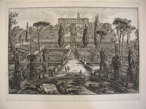
- A view of the Villa d'Este and its garden, depicting the central alley down the middle of the garden, with the villa rising above and outlined against the sky. The standpoint from which the view is taken lies at the centre of a circle of cypresses, the cypresses having been omitted to permit an unobstructed prospect of the garden. The effect of perspectival recession is intensified by an artifical but dramatic increase in the size of the foreground fountains and statues (representing the Liberal Arts), and by the diminutive stature of the human figures who work or saunter in the garden nearby. Along the central alley, which links a series of terraces mounting to the villa, are visible the "Fountain of Gentle Dragons", the so-called "viale de Cento Fontane", and the multistoried "Fountain of the Cups" attributed to Gian Lorenzo Bernini. In the far right background can be seen the "Fountain of the Birds" and the "Fountain of Proserpina". Variety and vertical accentuation in the composition are provided by a few cypresses and umbrella pines in the middle distance.
DR1985:0272
Description:
- A view of the Villa d'Este and its garden, depicting the central alley down the middle of the garden, with the villa rising above and outlined against the sky. The standpoint from which the view is taken lies at the centre of a circle of cypresses, the cypresses having been omitted to permit an unobstructed prospect of the garden. The effect of perspectival recession is intensified by an artifical but dramatic increase in the size of the foreground fountains and statues (representing the Liberal Arts), and by the diminutive stature of the human figures who work or saunter in the garden nearby. Along the central alley, which links a series of terraces mounting to the villa, are visible the "Fountain of Gentle Dragons", the so-called "viale de Cento Fontane", and the multistoried "Fountain of the Cups" attributed to Gian Lorenzo Bernini. In the far right background can be seen the "Fountain of the Birds" and the "Fountain of Proserpina". Variety and vertical accentuation in the composition are provided by a few cypresses and umbrella pines in the middle distance.
Personnes et institutions:
Sujet:
architecture, architecture de paysage, topographique
architecture, architecture de paysage, topographique
Date:
published 1773
published 1773
Titre:
A view of the Villa d'Este and its gardens, Tivoli
Actions:
DR1985:0272
Description:
- A view of the Villa d'Este and its garden, depicting the central alley down the middle of the garden, with the villa rising above and outlined against the sky. The standpoint from which the view is taken lies at the centre of a circle of cypresses, the cypresses having been omitted to permit an unobstructed prospect of the garden. The effect of perspectival recession is intensified by an artifical but dramatic increase in the size of the foreground fountains and statues (representing the Liberal Arts), and by the diminutive stature of the human figures who work or saunter in the garden nearby. Along the central alley, which links a series of terraces mounting to the villa, are visible the "Fountain of Gentle Dragons", the so-called "viale de Cento Fontane", and the multistoried "Fountain of the Cups" attributed to Gian Lorenzo Bernini. In the far right background can be seen the "Fountain of the Birds" and the "Fountain of Proserpina". Variety and vertical accentuation in the composition are provided by a few cypresses and umbrella pines in the middle distance.
Classification:
oeuvres d'art
oeuvres d'art
Date:
published 1773
published 1773
Personnes et institutions:
Sujet:
architecture, architecture de paysage, topographique
architecture, architecture de paysage, topographique
Niveau de description archivistique:
Sous-série
Sous-série
Titre:
Miscellanea
Miscellanea
Numéro de référence:
CI001.S1.D4
Description:
The three portfolios of "Croquis", originally attributed to Hubert Rohault de Fleury, but probably also including work by Charles, are particularly informative of the range of artistic and architectural interests of these architects. While some of the drawings in these portfolios may be travel sketches or based on travel sketches (Charles is known to have visited some of the locations depicted (1)), the majority are probably copied or adapted from books and prints. In some cases, these sources have been identified. The stylistic range of the drawings is eclectic; in addition to the expected Classical material, Gothic, Romanesque, Islamic, Exotic Revival (namely Etruscan and Egyptian), Renaissance and Baroque periods and styles as well as contemporary 19th century architecture are all represented. The subject matter is equally varied. DR1974:0002:032:001-066, two portfolios, includes arabesque ornament (some from Palazzo del Te and Palazzo Ducal in Mantua (2)), Islamic ornament motifs, tile patterns, Sicilian architectural subjects - mainly church interiors, and stonework and woodwork from Romanesque and Gothic structures . DR1974:0002:031:001-055, three portfolios, contains drawings of classical figures, Christian imagery and architectural sculpture from antique, medieval [?] and 19th century sources, sculpture from the 16th century sepulchral monument of Maximillian I, Italian Classical structures and contemporary classically-inspired subject matter including a number of Parisian fountains and monuments, and several English townhouses. DR1974:0002:030:001-065, four portfolios, includes drawings of Classical, Gothic and Exotic Revival buildings and interiors as well as a number of drawings of non-architectural subject matter including military subjects - fortification, armaments, soldiers, and revolutionary battle scenes - and topographic views. A folder of Italian views and buildings in this portfolio may have been intended for publication. The designs for interiors, Empire furniture, garden structures and several of the buildings are probably original designs by Hubert. (1) A description of Charles' travels based on his sketchbooks held by the Académie d'architecture is found in Académie d'architecture, 'Catalogue des collection' (Paris: Académie d'architecture, 1988) 35-36 and 230-241. (2) These drawings were copied from Wilhelm Zahn, 'Gemalte Ornamente von Julio Romano' (s.l., s.n, ca. 1833)., The three portfolios of "Croquis" were originally attributed to Hubert Rohault de Fleury, but probably also including work by Charles. The source and purpose of many of these drawings is unclear; some may be record drawings and travel sketches or based on travel sketches, but the majority are probably copied or adapted from books and prints. The stylistic range and subject matter of the drawings is broad and eclectic: arabesques, Islamic ornament, stonework and woodwork from Romanesque and Gothic structures (DR1974:0002:032:001-066); classical and Christian imagery, architectural sculpture from antique, medieval [?] and 19th century sources, Italian Classical structures, nineteenth century classically-inspired subject matter (DR1974:0002:031:001-055); non-architectural subject matter including military subjects, topographic views, and Italian views and buildings, possibly intended for publication (DR1974:0002:030:001-065). Portfolio, DR1974:0002:030:001-065 also includes interiors, Empire furniture, garden structures and Classical, Gothic and Exotic Revival buildings, some of which are probably original designs by Hubert Rohault de Fleury. Bibliography: - Bergdoll, Barry. "Hubert Rohault de Fleury: Cinquième Partie: Équisses et Dessins d'Ornament." 'CCA Research Report.' n.d. - Académie d'architecture (France). 'Catalogue des collections' (Paris: L'Academie, 1988), 35-37 and 230-241.
Personnes et institutions:
Date:
[1800-1868]
[1800-1868]
Titre:
Miscellanea
CI001.S1.D4
Description:
The three portfolios of "Croquis", originally attributed to Hubert Rohault de Fleury, but probably also including work by Charles, are particularly informative of the range of artistic and architectural interests of these architects. While some of the drawings in these portfolios may be travel sketches or based on travel sketches (Charles is known to have visited some of the locations depicted (1)), the majority are probably copied or adapted from books and prints. In some cases, these sources have been identified. The stylistic range of the drawings is eclectic; in addition to the expected Classical material, Gothic, Romanesque, Islamic, Exotic Revival (namely Etruscan and Egyptian), Renaissance and Baroque periods and styles as well as contemporary 19th century architecture are all represented. The subject matter is equally varied. DR1974:0002:032:001-066, two portfolios, includes arabesque ornament (some from Palazzo del Te and Palazzo Ducal in Mantua (2)), Islamic ornament motifs, tile patterns, Sicilian architectural subjects - mainly church interiors, and stonework and woodwork from Romanesque and Gothic structures . DR1974:0002:031:001-055, three portfolios, contains drawings of classical figures, Christian imagery and architectural sculpture from antique, medieval [?] and 19th century sources, sculpture from the 16th century sepulchral monument of Maximillian I, Italian Classical structures and contemporary classically-inspired subject matter including a number of Parisian fountains and monuments, and several English townhouses. DR1974:0002:030:001-065, four portfolios, includes drawings of Classical, Gothic and Exotic Revival buildings and interiors as well as a number of drawings of non-architectural subject matter including military subjects - fortification, armaments, soldiers, and revolutionary battle scenes - and topographic views. A folder of Italian views and buildings in this portfolio may have been intended for publication. The designs for interiors, Empire furniture, garden structures and several of the buildings are probably original designs by Hubert. (1) A description of Charles' travels based on his sketchbooks held by the Académie d'architecture is found in Académie d'architecture, 'Catalogue des collection' (Paris: Académie d'architecture, 1988) 35-36 and 230-241. (2) These drawings were copied from Wilhelm Zahn, 'Gemalte Ornamente von Julio Romano' (s.l., s.n, ca. 1833)., The three portfolios of "Croquis" were originally attributed to Hubert Rohault de Fleury, but probably also including work by Charles. The source and purpose of many of these drawings is unclear; some may be record drawings and travel sketches or based on travel sketches, but the majority are probably copied or adapted from books and prints. The stylistic range and subject matter of the drawings is broad and eclectic: arabesques, Islamic ornament, stonework and woodwork from Romanesque and Gothic structures (DR1974:0002:032:001-066); classical and Christian imagery, architectural sculpture from antique, medieval [?] and 19th century sources, Italian Classical structures, nineteenth century classically-inspired subject matter (DR1974:0002:031:001-055); non-architectural subject matter including military subjects, topographic views, and Italian views and buildings, possibly intended for publication (DR1974:0002:030:001-065). Portfolio, DR1974:0002:030:001-065 also includes interiors, Empire furniture, garden structures and Classical, Gothic and Exotic Revival buildings, some of which are probably original designs by Hubert Rohault de Fleury. Bibliography: - Bergdoll, Barry. "Hubert Rohault de Fleury: Cinquième Partie: Équisses et Dessins d'Ornament." 'CCA Research Report.' n.d. - Académie d'architecture (France). 'Catalogue des collections' (Paris: L'Academie, 1988), 35-37 and 230-241.
Niveau de description archivistique:
File 4
File 4
Date:
[1800-1868]
[1800-1868]
Personnes et institutions:
Niveau de description archivistique:
Projet
Projet
Numéro de référence:
AP164.S1.1988.D3
Description:
This project series documents the competition and the construction of a residential building including commercial space, near the motorway M-30, in Madrid, Spain (Arregui y Aruej and de Valderribas Streets). The firm worked with Antonio Rivera and Juan López. The firm identified this project as number 50. In 1988, Abalos & Herreros won first prize for this project at the competition organised by the firm Empresa Municipal de la Vivienda (EMV) from Madrid. In 1997, the firm also received an award from the Comunidad de Madrid for “healthy” housing. Documenting the project are conceptual, design development and working drawings, correspondence, notes, project descriptions, reference and photographic materials.
Personnes et institutions:
Date:
1987-1997
1987-1997
Titre:
Viviendas, locales y garajes en la M-30, Madrid, Spain (1988)
Actions:
AP164.S1.1988.D3
Description:
This project series documents the competition and the construction of a residential building including commercial space, near the motorway M-30, in Madrid, Spain (Arregui y Aruej and de Valderribas Streets). The firm worked with Antonio Rivera and Juan López. The firm identified this project as number 50. In 1988, Abalos & Herreros won first prize for this project at the competition organised by the firm Empresa Municipal de la Vivienda (EMV) from Madrid. In 1997, the firm also received an award from the Comunidad de Madrid for “healthy” housing. Documenting the project are conceptual, design development and working drawings, correspondence, notes, project descriptions, reference and photographic materials.
Niveau de description archivistique:
Project
Project
Date:
1987-1997
1987-1997
Personnes et institutions:
Niveau de description archivistique:
Projet
Projet
Numéro de référence:
AP164.S1.1988.D4
Description:
This project series documents the design for the Plaza de Opera, residential units and interchange, in Madrid, Spain. The firm identified this project as number 51. In 1988, Abalos & Herreros won second prize (ex-aequo) for this project at the national competition “De Opera: plaza, viviendas e intercambiador,” organised by the Colegio Oficial de Arquitectos de Madrid (C.O.A.M.). Abalos & Herreros worked with the following collaborators: Juan Manuel Fernández, Almudena García, Paloma Gómez, Jimena Robles, Miguel Santiago, Aurelio Cantero, José Maria Luzón and F. Javier Pascual. Documenting the project are design development and working drawings, one textual record and a model.
Personnes et institutions:
Date:
circa 1988
circa 1988
Titre:
Propuesta para la Plaza de Ópera, Madrid, Spain (1988)
Actions:
AP164.S1.1988.D4
Description:
This project series documents the design for the Plaza de Opera, residential units and interchange, in Madrid, Spain. The firm identified this project as number 51. In 1988, Abalos & Herreros won second prize (ex-aequo) for this project at the national competition “De Opera: plaza, viviendas e intercambiador,” organised by the Colegio Oficial de Arquitectos de Madrid (C.O.A.M.). Abalos & Herreros worked with the following collaborators: Juan Manuel Fernández, Almudena García, Paloma Gómez, Jimena Robles, Miguel Santiago, Aurelio Cantero, José Maria Luzón and F. Javier Pascual. Documenting the project are design development and working drawings, one textual record and a model.
Niveau de description archivistique:
Project
Project
Date:
circa 1988
circa 1988
Personnes et institutions:
Niveau de description archivistique:
Projet
Projet
Numéro de référence:
AP164.S1.1993.D6
Description:
The project series documents the competition entry for the plan and design of the “Dune Park,” in the Doñana National Park. The competition was organised by the Consejeria de Obras Públicas y Transportes, Junta de Andalucia, Spain. The firm identified this project as number 84. Abalos & Herreros worked with collaborators Ángel Borrego, Pilar González Santoyo and Rafael Hernández. The firm's entry proposed “[…] the most advanced experiences in preservation, restoration and reconversion of environmental heritage in the contemporary tourist offer : Access to the Dune Park and Matalascañas; Atlantic balcony[?]; Beach and naturist colony; Park.” (ARCH277386) Documenting this project are conceptual and presentation drawings, cartographic, graphic, photographic and reference materials, project descriptions, dummies and a poster.
Personnes et institutions:
Date:
circa 1992-1993
circa 1992-1993
Titre:
Parque Dunar, Doñana National Park, Spain
Actions:
AP164.S1.1993.D6
Description:
The project series documents the competition entry for the plan and design of the “Dune Park,” in the Doñana National Park. The competition was organised by the Consejeria de Obras Públicas y Transportes, Junta de Andalucia, Spain. The firm identified this project as number 84. Abalos & Herreros worked with collaborators Ángel Borrego, Pilar González Santoyo and Rafael Hernández. The firm's entry proposed “[…] the most advanced experiences in preservation, restoration and reconversion of environmental heritage in the contemporary tourist offer : Access to the Dune Park and Matalascañas; Atlantic balcony[?]; Beach and naturist colony; Park.” (ARCH277386) Documenting this project are conceptual and presentation drawings, cartographic, graphic, photographic and reference materials, project descriptions, dummies and a poster.
Niveau de description archivistique:
Project
Project
Date:
circa 1992-1993
circa 1992-1993
Personnes et institutions:
Niveau de description archivistique:
Projet
Projet
Numéro de référence:
AP178.S1.1998.PR07
Description:
This project series documents the C. Cultural e Audit. para a Fundação Ibere Camargo in Porto Alegre, Brazil. While the records were held in the office’s archives this project was assigned the number 102/90. The office assigned the date 1998 to this project. At the end of the nineties, an architectural competition was held for the construction of a new building for the Iberê Camargo Foundation. The foundation holds the archives and work of the Brazilian painter Ibere Carmargo, as well as hosts temporary exhibitions and seminars. The project site is located near the Guaíba River, between a cliff and the Avenida Padre Cacique. Collaborators on the project were Barbara Rangel, Pedro Polonia, Michele Gigante, Francesca Montalto, Atsushi Ueno, Rita Amaral, José Luiz Cana, and Camargo Correa. The three-stories building is 88,000 square feet and includes nine galleries, storage spaces, offices, a bookstore, an auditorium, and a video library. Each of the galleries is independent but linked via a system of ramps. One of the unique qualities of the building are the ramps that come out of its concrete façade. Due to the limited space, the parking was built below the Avenida Padre Cacique. The building respects the concept of sustainable development, with a sewage treatment station that redistributes the water to the surrounding vegetation. The museum was Siza's first built project in Brazil and it was inaugurated in 2008. Siza received the Golden Lion award at the Venice Architecture Biennale in 2003 for this project. Documenting this project are sketches, studies, preliminary drawings, working drawings, technical drawings, and electrical drawings. Textual material includes project documentation, correspondence, and documentation regarding exhibitions about the building. Photographic material documents the models, project site, and built project.
Personnes et institutions:
Date:
1998-2006
1998-2006
Titre:
C. Cultural e Audit. para a Fundação Iberê Camargo [Iberê Camargo Foundation Museum], Porto Alegre, Brazil (1998)
Actions:
AP178.S1.1998.PR07
Description:
This project series documents the C. Cultural e Audit. para a Fundação Ibere Camargo in Porto Alegre, Brazil. While the records were held in the office’s archives this project was assigned the number 102/90. The office assigned the date 1998 to this project. At the end of the nineties, an architectural competition was held for the construction of a new building for the Iberê Camargo Foundation. The foundation holds the archives and work of the Brazilian painter Ibere Carmargo, as well as hosts temporary exhibitions and seminars. The project site is located near the Guaíba River, between a cliff and the Avenida Padre Cacique. Collaborators on the project were Barbara Rangel, Pedro Polonia, Michele Gigante, Francesca Montalto, Atsushi Ueno, Rita Amaral, José Luiz Cana, and Camargo Correa. The three-stories building is 88,000 square feet and includes nine galleries, storage spaces, offices, a bookstore, an auditorium, and a video library. Each of the galleries is independent but linked via a system of ramps. One of the unique qualities of the building are the ramps that come out of its concrete façade. Due to the limited space, the parking was built below the Avenida Padre Cacique. The building respects the concept of sustainable development, with a sewage treatment station that redistributes the water to the surrounding vegetation. The museum was Siza's first built project in Brazil and it was inaugurated in 2008. Siza received the Golden Lion award at the Venice Architecture Biennale in 2003 for this project. Documenting this project are sketches, studies, preliminary drawings, working drawings, technical drawings, and electrical drawings. Textual material includes project documentation, correspondence, and documentation regarding exhibitions about the building. Photographic material documents the models, project site, and built project.
Niveau de description archivistique:
Project
Project
Date:
1998-2006
1998-2006
Personnes et institutions:
Niveau de description archivistique:
Projet
Projet
Numéro de référence:
AP018.S1.1974.PR22
Description:
This project series documents the design and construction of the medical clinic building at the Etobicoke General Hospital site in Etobicoke, Ontario from 1974-1980. The office identified the project number as 7428. At the same time that Parkin Architects Planners was constructing the Etobicoke General Hospital, they began working on this project, an adjacent medical clinic that would be attached to the hospital via tunnel. This project consisted of an 80 suite medical centre with a proposed space of 65,000 square feet including the building’s basement. The building shared architectural unity with the neighbouring hospital but was built at a distance in order to allow for future expansions of the hospital. In the project materials, the building is also referred to as the Professional Building. A prominent part of this project was design work for the radiology department in the clinic. It should be noted when viewing textual records and drawings in this project series that many are entitled Rexdale Radiological Services Limited. This project originally began under a different project number assigned by the office, but was built under this project number after the building's location was changed. This original project is also described in the fonds (see project series AP018.S1.1972.PR14). The project is recorded through drawings, photographs and textual records dating from 1974-1980. A large part of the drawings show site plans, but elevations, sections, details and floor plans are also included. The photographs track the construction progress of the project. The textual records include correspondence, meeting minutes and reports, specifications, tender documents, change orders, supplementary instructions, design records, site reports and detail planning records. Box AP018.S1.1974.PR22.009 contains an index to the textual records, which was created by the office.
Personnes et institutions:
Date:
1974-1980
1974-1980
Titre:
Etobicoke General Hospital, Medical Clinic Building, Etobicoke Ontario (1974-1980)
Actions:
AP018.S1.1974.PR22
Description:
This project series documents the design and construction of the medical clinic building at the Etobicoke General Hospital site in Etobicoke, Ontario from 1974-1980. The office identified the project number as 7428. At the same time that Parkin Architects Planners was constructing the Etobicoke General Hospital, they began working on this project, an adjacent medical clinic that would be attached to the hospital via tunnel. This project consisted of an 80 suite medical centre with a proposed space of 65,000 square feet including the building’s basement. The building shared architectural unity with the neighbouring hospital but was built at a distance in order to allow for future expansions of the hospital. In the project materials, the building is also referred to as the Professional Building. A prominent part of this project was design work for the radiology department in the clinic. It should be noted when viewing textual records and drawings in this project series that many are entitled Rexdale Radiological Services Limited. This project originally began under a different project number assigned by the office, but was built under this project number after the building's location was changed. This original project is also described in the fonds (see project series AP018.S1.1972.PR14). The project is recorded through drawings, photographs and textual records dating from 1974-1980. A large part of the drawings show site plans, but elevations, sections, details and floor plans are also included. The photographs track the construction progress of the project. The textual records include correspondence, meeting minutes and reports, specifications, tender documents, change orders, supplementary instructions, design records, site reports and detail planning records. Box AP018.S1.1974.PR22.009 contains an index to the textual records, which was created by the office.
Niveau de description archivistique:
Project
Project
Date:
1974-1980
1974-1980
Personnes et institutions: