36518 Résultats
Classification:
photographies
photographies
Numéro de référence:
PH1978:0040.01
Description:
First of a series of five illustrated volumes, this album contains mounted plates, engravings and maps, and depicts bridges, viaducts, railways and roads mainly in France (one in Corsica), and two in Constantine, Algeria. Album (Tome I) is titled as follows: Les Travaux Publics de la France. Route et Ponts - Chemins de fer - Rivières et canaux/ Ports de mer - Phares et balises/ par/ MM. F. Lucas et V. Fournié - Ed. Collignon - H. de Lagrené/ Voisin Bey - E. Allard/ ouvrage publié sous les auspices/ du Ministère des Travaux Publics et sous la direction de/ M. Léonce Reynaud/ Inspecteur général des Ponts et Chaussées/ Tome Premier: Routes et Ponts/ par/ Félix Lucas et Victor Fournié/ Ingénieurs en Chef des Ponts et Chaussées/ avec 50 planches phototypées, 100 gravures et une carte en chromolithographie/ Paris/ J. Rothschild, Éditeur 13 rue des Saints-Pères, 13 M DCCC LXXXIII and the album is divided as follows: Préface, dated 'novembre 1879' - Léonce Reynaud (biographical note on Léonce Reynaud) with lithograph glued and signed by Jules Lefebre and Léon Gaucherel - Routes et Ponts. Introduction - Chapitre Premier. Époque Gallo-Romaine - Chapitre II. Le Moyen Age et les Temps Modernes - Chapitre III. Époque contemporaine - Chapitre IV. Statistique - Explications des planches - Table des matières - Table alphabétique des matières, des figures et des 50 planches. The 50 plates are listed as follows: I Défilé de la CLue de Saint-André, près de Nice (Alpes-Maritimes) II Gorges de La Loue (Doubs) III Route Nationale no 20, dans les Pyrénées (Ariège) IV Souterrain de Duranus (Alpes-Maritimes) V Défil de Lantosque (Alpes-Maritimes) VI Grotte du Mas-d'Azil ou de l'Arize (Ariège) VII Chemin de la Corniche à Marseille VIII Route de la Grande Chartreuse (Isère) IX Détroit du Cieix (Savoie) XI Route dans la Vallée du Tech (Pyrénées-Orientales) XII Pont de Valentré, sur le Lot, à Cahors XIII Pont-neuf, sur la Seine, à Paris XIV Pont de Bétharram (Basses-Pyrénées) XV Pont du Gouedic (Côtes-du-Nord) XVI Ponte Nuovo (Corse) XVII Pont de Lavaur (Tarn) XVIII Pont Saint-Louis XIX Pont de Bordeaux XX Pont de Vieille-Brioude (Haute-Loire) XXI Viaduc de Dinan (Côtes-du-Nord) XXII Pont des Invalides, sur la Seine, à Paris XXIII Pont de l'Alma, sur la Seine, à Paris XXIV Viaduc sur le Torrent de Saint-Ferréol (Alpes-Maritimes) XXV Pont de Mascas, sur la Vésubie (Alpes-Maritimes) XXVI Pont de Saint-Sauveur (Hautes-Pyrénées) XXVII Pont-Viaduc du Point-du-Jour, à Paris XXVIII Pont-neuf à Albi (Tarn) XXIX Pont de Chaabet-El-Akhra (Constantine) XXX Viaduc du Duzon (Ardèche) XXXI Pont de Pau (Pont de Jurançon) XXXII Ponts de Claix (Isère) XXXIII Pont de la Trinité XXXIV Pont des Saints-Pères, à Paris XXXV Pont d'Arcole, à Paris XXXVI Pont Saint-Esprit, sur le Rhone (Gard) XXXVII Pont de Solferino, à Paris XXXVIII Pont de la Grande-Jatte (Seine) XXXIX Pont Saint-Louis, à Paris XL Pont du Var, près de Nice (Alpes-Maritimes) XLI Pont d'El Kantara, à Constantine XLII Pont de Vichy, sur l'Allier (Allier) XLIII Pont Garibaldi, sur le Paillon, à Nice XLIV Pont de Clichy-La-Garenne (Seine) XLV Pont de Grenelle, sur la Seine, à Paris XLVI Pont Sully, sur la Seine, à Paris XLVII Pont de La Roche-Bernard (Morbihan) XLVIII Pont de Saint-Christophe sur le Scorff (Morbihan) XLIX Pont de La Mescla, sur le Var (Alpes-Maritimes) L Pont tournant des bassins de Radoub de Marseille
Personnes et institutions:
Sujet:
ingénierie, topographique
ingénierie, topographique
Date:
between 1876-1883
between 1876-1883
Titre:
Les Travaux Publics de la France. Tome 1. Routes et Ponts
Actions:
PH1978:0040.01
Description:
First of a series of five illustrated volumes, this album contains mounted plates, engravings and maps, and depicts bridges, viaducts, railways and roads mainly in France (one in Corsica), and two in Constantine, Algeria. Album (Tome I) is titled as follows: Les Travaux Publics de la France. Route et Ponts - Chemins de fer - Rivières et canaux/ Ports de mer - Phares et balises/ par/ MM. F. Lucas et V. Fournié - Ed. Collignon - H. de Lagrené/ Voisin Bey - E. Allard/ ouvrage publié sous les auspices/ du Ministère des Travaux Publics et sous la direction de/ M. Léonce Reynaud/ Inspecteur général des Ponts et Chaussées/ Tome Premier: Routes et Ponts/ par/ Félix Lucas et Victor Fournié/ Ingénieurs en Chef des Ponts et Chaussées/ avec 50 planches phototypées, 100 gravures et une carte en chromolithographie/ Paris/ J. Rothschild, Éditeur 13 rue des Saints-Pères, 13 M DCCC LXXXIII and the album is divided as follows: Préface, dated 'novembre 1879' - Léonce Reynaud (biographical note on Léonce Reynaud) with lithograph glued and signed by Jules Lefebre and Léon Gaucherel - Routes et Ponts. Introduction - Chapitre Premier. Époque Gallo-Romaine - Chapitre II. Le Moyen Age et les Temps Modernes - Chapitre III. Époque contemporaine - Chapitre IV. Statistique - Explications des planches - Table des matières - Table alphabétique des matières, des figures et des 50 planches. The 50 plates are listed as follows: I Défilé de la CLue de Saint-André, près de Nice (Alpes-Maritimes) II Gorges de La Loue (Doubs) III Route Nationale no 20, dans les Pyrénées (Ariège) IV Souterrain de Duranus (Alpes-Maritimes) V Défil de Lantosque (Alpes-Maritimes) VI Grotte du Mas-d'Azil ou de l'Arize (Ariège) VII Chemin de la Corniche à Marseille VIII Route de la Grande Chartreuse (Isère) IX Détroit du Cieix (Savoie) XI Route dans la Vallée du Tech (Pyrénées-Orientales) XII Pont de Valentré, sur le Lot, à Cahors XIII Pont-neuf, sur la Seine, à Paris XIV Pont de Bétharram (Basses-Pyrénées) XV Pont du Gouedic (Côtes-du-Nord) XVI Ponte Nuovo (Corse) XVII Pont de Lavaur (Tarn) XVIII Pont Saint-Louis XIX Pont de Bordeaux XX Pont de Vieille-Brioude (Haute-Loire) XXI Viaduc de Dinan (Côtes-du-Nord) XXII Pont des Invalides, sur la Seine, à Paris XXIII Pont de l'Alma, sur la Seine, à Paris XXIV Viaduc sur le Torrent de Saint-Ferréol (Alpes-Maritimes) XXV Pont de Mascas, sur la Vésubie (Alpes-Maritimes) XXVI Pont de Saint-Sauveur (Hautes-Pyrénées) XXVII Pont-Viaduc du Point-du-Jour, à Paris XXVIII Pont-neuf à Albi (Tarn) XXIX Pont de Chaabet-El-Akhra (Constantine) XXX Viaduc du Duzon (Ardèche) XXXI Pont de Pau (Pont de Jurançon) XXXII Ponts de Claix (Isère) XXXIII Pont de la Trinité XXXIV Pont des Saints-Pères, à Paris XXXV Pont d'Arcole, à Paris XXXVI Pont Saint-Esprit, sur le Rhone (Gard) XXXVII Pont de Solferino, à Paris XXXVIII Pont de la Grande-Jatte (Seine) XXXIX Pont Saint-Louis, à Paris XL Pont du Var, près de Nice (Alpes-Maritimes) XLI Pont d'El Kantara, à Constantine XLII Pont de Vichy, sur l'Allier (Allier) XLIII Pont Garibaldi, sur le Paillon, à Nice XLIV Pont de Clichy-La-Garenne (Seine) XLV Pont de Grenelle, sur la Seine, à Paris XLVI Pont Sully, sur la Seine, à Paris XLVII Pont de La Roche-Bernard (Morbihan) XLVIII Pont de Saint-Christophe sur le Scorff (Morbihan) XLIX Pont de La Mescla, sur le Var (Alpes-Maritimes) L Pont tournant des bassins de Radoub de Marseille
Classification:
photographies
photographies
Date:
between 1876-1883
between 1876-1883
Personnes et institutions:
Sujet:
ingénierie, topographique
ingénierie, topographique
Numéro de référence:
PH1978:0040.02
Description:
Second of a series of five illustrated volumes, this album contains mounted plates, engravings and maps, and depicts viaducts, bridges, tunnels, train stations and railways in France. Album (Tome 2) is titled as follows: Les Travaux Publics de la France. Route et ponts - chemins de fer - rivières et canaux/ ports de mer - phares et balises/ par/ MM. F. Lucas et V. Fournié - Ed. Collignon - H. de Lagrené/ Voisin Bey - E. Allard/ ouvrage publié sous les auspices/ du Ministère des Travaux Publics et sous la direction de/ M. Léonce Reynaud/ Inspecteur général des Ponts et Chaussées/ Tome Deuxième: Chemins de fer/ par/ Édouard Collignon/ Ingénieur en Chef des Ponts et Chaussées/ avec 50 planches phototypées, 57 gravures et une carte en chromolithographie/ Paris/ J. Rothschild, Éditeur 13 rue des Saints-Pères, 13 M DCCC LXXXIII and the album is divided as follows: - Chapitre Premier. De La Voie - Chapitre II. De la locomotive - Chapitre III. Des wagons - Chapitre IV. Des stations - Chapitre V. De l'exploitation - Chapitre VI. Les chemins de fer au point de vue législatif et au point de vue financier - Chapitre VII. Des chemins de fer dans certaines circonstances exceptionnelles - Chapitre VIII. Statistique - Explication des planches - Table des matières et des 50 planches The 50 plates are listed as follows: I Viaduc de Morlaix (Réseau de l'Ouest) II Gare du chemin de fer du nord III Viaduc de Poix (Chemin de fer du nord) IV Viaduc de Chaumont (Réseau de l'Est, ligne de Paris à Mulhouse) V Viaduc de Pompadour VI Viaduc de Veyrière (Réseau d'Orléans) VII Viaduc de Vignols (Réseau d'Orléans) VIII Viaduc de Port-Launay ou de Guily-Glass (Réseau d'Orléans) IX et X Viaduc de Meil-ar-Guidy ou Pont de Buis (Réseau d'Orléans) XI Viaduc de Lapeyrière (Réseau d'Orléans) XII et XIII Viaduc de la Sioulle (Réseau d'Orléans) XIV et XV Viaduc du Bellon (Réseau d'Orléans) XVI Viaduc de La Bouble (Réseau d'Orléans) XVII Viaduc de Busseau d'Ahun (Réseau d'Orléans) XVIII Pont sur la Vézère (Réseau d'Orléans) XIX et XX Pont du Scorff (Réseau d'Orléans) XXI Pont de Chalonnes (Réseau d'Orléans) XXII Pont de Luzech (Réseau d'Orléans) XXIII Viaduc de L'Aiguille (Réseau d'Orléans) XXIV Tunnel de Saint-Solve (Réseau d'Orléans) XXV Tunnel de Fraisse-Haut (Réseau d'Orléans) XXVI et XVII Gare du chemin de fer d'Orléans à Paris (Réseau d'Orléans) XXVIII Gare de Murat (Réseau d'Orléans) XXIX Gare de Sainte-Anne-D'Auray (Réseau d'Orléans) XXX Gare de Lorient (Réseau d'Orléans) XXXI Vue de Castelfranc (Lot) (Réseau d'Orléans) XXXII Pont sur la Chiffa (Ligne d'Alger à Oran) XXXIII Viaduc de la Selle (Chemin de fer de Lyon) XXXIV Viaduc sur le Drac (Chemin de fer de Lyon) XXXV Viaduc de Saint-Michel-les-Portes (Chemin de fer de Lyon) XXXVI Viaduc de Lyon sur le Rhone (Chemin de fer de Lyon à la Méditerranée) XXXVII Viaduc de Tarascon (Chemin de fer de Lyon) XXXVIII Tunnel de la Nerthe (Chemin de fer de Lyon) XXXIX Pont de Culoz (Chemin de fer de Lyon) XL Pont sur la Garonne (Réseau du Midi) XLI Pont de l'Orb (Chemin de fer du Midi) XLII Pont de Langon (Chemin de fer du Midi) XLIII Viaduc de Lanespède (Chemin de fer du Midi) XLIV Pont de Berdoulet XLV Viaduc de Bédarieux (Chemin de fer du Midi) XLVI Pont de l'Aude (Chemin de fer du Midi) XLVII Viaduc de l'Osse (Chemin de fer du Midi) XLVIII Viaduc de l'Usclade (Chemin de fer du Midi) XLIX Pont sur la Bidassoa (Chemin de fer du Midi) L Vallée du Gave de Pau (Réseau du Midi)
Personnes et institutions:
Sujet:
ingénierie
ingénierie
Date:
between 1876-1883
between 1876-1883
Titre:
Les Travaux Publics de la France. Tome 2. Chemins de fer
Actions:
PH1978:0040.02
Description:
Second of a series of five illustrated volumes, this album contains mounted plates, engravings and maps, and depicts viaducts, bridges, tunnels, train stations and railways in France. Album (Tome 2) is titled as follows: Les Travaux Publics de la France. Route et ponts - chemins de fer - rivières et canaux/ ports de mer - phares et balises/ par/ MM. F. Lucas et V. Fournié - Ed. Collignon - H. de Lagrené/ Voisin Bey - E. Allard/ ouvrage publié sous les auspices/ du Ministère des Travaux Publics et sous la direction de/ M. Léonce Reynaud/ Inspecteur général des Ponts et Chaussées/ Tome Deuxième: Chemins de fer/ par/ Édouard Collignon/ Ingénieur en Chef des Ponts et Chaussées/ avec 50 planches phototypées, 57 gravures et une carte en chromolithographie/ Paris/ J. Rothschild, Éditeur 13 rue des Saints-Pères, 13 M DCCC LXXXIII and the album is divided as follows: - Chapitre Premier. De La Voie - Chapitre II. De la locomotive - Chapitre III. Des wagons - Chapitre IV. Des stations - Chapitre V. De l'exploitation - Chapitre VI. Les chemins de fer au point de vue législatif et au point de vue financier - Chapitre VII. Des chemins de fer dans certaines circonstances exceptionnelles - Chapitre VIII. Statistique - Explication des planches - Table des matières et des 50 planches The 50 plates are listed as follows: I Viaduc de Morlaix (Réseau de l'Ouest) II Gare du chemin de fer du nord III Viaduc de Poix (Chemin de fer du nord) IV Viaduc de Chaumont (Réseau de l'Est, ligne de Paris à Mulhouse) V Viaduc de Pompadour VI Viaduc de Veyrière (Réseau d'Orléans) VII Viaduc de Vignols (Réseau d'Orléans) VIII Viaduc de Port-Launay ou de Guily-Glass (Réseau d'Orléans) IX et X Viaduc de Meil-ar-Guidy ou Pont de Buis (Réseau d'Orléans) XI Viaduc de Lapeyrière (Réseau d'Orléans) XII et XIII Viaduc de la Sioulle (Réseau d'Orléans) XIV et XV Viaduc du Bellon (Réseau d'Orléans) XVI Viaduc de La Bouble (Réseau d'Orléans) XVII Viaduc de Busseau d'Ahun (Réseau d'Orléans) XVIII Pont sur la Vézère (Réseau d'Orléans) XIX et XX Pont du Scorff (Réseau d'Orléans) XXI Pont de Chalonnes (Réseau d'Orléans) XXII Pont de Luzech (Réseau d'Orléans) XXIII Viaduc de L'Aiguille (Réseau d'Orléans) XXIV Tunnel de Saint-Solve (Réseau d'Orléans) XXV Tunnel de Fraisse-Haut (Réseau d'Orléans) XXVI et XVII Gare du chemin de fer d'Orléans à Paris (Réseau d'Orléans) XXVIII Gare de Murat (Réseau d'Orléans) XXIX Gare de Sainte-Anne-D'Auray (Réseau d'Orléans) XXX Gare de Lorient (Réseau d'Orléans) XXXI Vue de Castelfranc (Lot) (Réseau d'Orléans) XXXII Pont sur la Chiffa (Ligne d'Alger à Oran) XXXIII Viaduc de la Selle (Chemin de fer de Lyon) XXXIV Viaduc sur le Drac (Chemin de fer de Lyon) XXXV Viaduc de Saint-Michel-les-Portes (Chemin de fer de Lyon) XXXVI Viaduc de Lyon sur le Rhone (Chemin de fer de Lyon à la Méditerranée) XXXVII Viaduc de Tarascon (Chemin de fer de Lyon) XXXVIII Tunnel de la Nerthe (Chemin de fer de Lyon) XXXIX Pont de Culoz (Chemin de fer de Lyon) XL Pont sur la Garonne (Réseau du Midi) XLI Pont de l'Orb (Chemin de fer du Midi) XLII Pont de Langon (Chemin de fer du Midi) XLIII Viaduc de Lanespède (Chemin de fer du Midi) XLIV Pont de Berdoulet XLV Viaduc de Bédarieux (Chemin de fer du Midi) XLVI Pont de l'Aude (Chemin de fer du Midi) XLVII Viaduc de l'Osse (Chemin de fer du Midi) XLVIII Viaduc de l'Usclade (Chemin de fer du Midi) XLIX Pont sur la Bidassoa (Chemin de fer du Midi) L Vallée du Gave de Pau (Réseau du Midi)
Date:
between 1876-1883
between 1876-1883
Personnes et institutions:
Sujet:
ingénierie
ingénierie
Numéro de référence:
PH1978:0040.03
Description:
Third of a series of five illustrated volumes, this album contains mounted plates, engravings and maps (one map on two-pages), and depicts lock gates, dams, bridges, channels, subterraneans, aqueducs, canal-bridges, water towers and reservoirs in France. Album (Tome 3) is titled as follows: Les Travaux Publics de la France. Route et ponts - chemins de fer - rivières et canaux/ ports de mer - phares et balises/ par/ MM. F. Lucas et V. Fournié - Ed. Collignon - H. de Lagrené/ Voisin Bey - E. Allard/ ouvrage publié sous les auspices/ du Ministère des Travaux Publics et sous la direction de/ M. Léonce Reynaud/ Inspecteur général des Ponts et Chaussées/ Tome Troisième: Rivières et canaux/ Eaux des villes - Irrigations et assainissement des terres/ par/H. De Lagrené/ Ingénieur en Chef des Ponts et Chaussées/ avec 50 planches phototypées, 109 gravures et une carte en chromolithographie/ Paris/ J. Rothschild, Éditeur 13 rue des Saints-Pères, 13 M DCCC LXXXIII and the album is divided as follows: Rivières et Canaux - Introduction - Chapitre Premier. Historique de la navigation intérieure en France - Chapitre II. Considérations sur les voies navigables en particulier - Chapitre III. Navigation sur les rivières non canalisées - Chapitre IV. Canalisation en lit de rivière - Chapitre V. Canaux de navigation Deuxième Partie Alimentation en eau des villes - Chapitre Premier. Indications générales - Chapitre II. Travaux relatifs à l'alimentation en eau des villes - Chapitre III. Travaux relatifs à la distribution des eaux des villes - Chapitre IV. Travaux d'égout et de drainage des villes - Chapitre V. Utilisation des eaux d'égout - Chapitre VI. Alimentation en eau et assainissement de Paris Troisième Partie Emploi des eaux pour fertiliser les terres - Chapitre Premier. Considérations générales - Chapitre II. Approvisionnement des eaux d'irrigation - Chapitre III. Travaux relatifs à la conduite des eaux d'irrigation - Chapitre IV. Pratique des irrigations - Chapitre V. Colmatages Quatrième Partie Desséchement, drainage, travaux de défense contre les inondations - Chapitre Premier. Desséchements - Chapitre II. Drainage - Chapitre III. Des inondations - Explication des planches - Table des matières Plates are listed as follows: I Barrage de Seine-Port II Barrage duPort-à-l'Anglais III, IV et V Barrage de Port-Villez VI Portes de l'écluse de Bougival VII Écluse de la Boutonne VIII Port de Javel IX Pont de Ranville X Vue du canal latéral à la Garonne XI Prise d'eau du canal latéral à Toulouse XII Jonction du canal du Midi et du canal latéral à la Garonne XIII Écluses de Castets (Canal latéral à la Garonne) XIV Souterrain de Malpas (Canal du Midi) XV Écluse octuple de Fonserannes XVI Pont canal de Béziers XVII et XIII Réservoir de Lampy (Canal du Midi) XIX Réservoir de Saint-Ferréol (Canal du Midi) XX Écluse de Saint-Julien (Canal du centre) XXI Les sept écluses (Canal du centre) XXII Pont canal de la Bourbince (sur la rigole navigable de l'Arroux, canal du centre) XXIII Tranchée aux abords du souterrain de Pouilly (Canal de Bourgogne) XXIV Réservoir de Gros-Bois (Canal de Bourgogne) XXV Pont canal de Saint-Florentin (Canal de Bourgogne) XXVI Pont aqueduc de Montreillon (Canal du Nivernais) XXVII Pont canal du Guétin (Canal latéral à la Loire) XXVIII Pont canal de Barberey (Canal de la haute Seine) XXIX Traversée de la ville de Troyes par le Canal de la haute Seine XXX, XXXI, XXXII, XXXIII, XXXIV, XXXV, XXXVI et XXXVII Canal de Nantes à Brest XXXVIII Aqueduc de Roquefavour XXXIX Chateau-d'eau de Marseille XL, XLI, XLII, XLIII, XLIV et XLV Dérivation de la Vanne XLVI et XVII Distribution d'eau de Nice XLVIII Réservoir du Furens XLIX Réservoir de Ternay L Canal du Verdon
Personnes et institutions:
Sujet:
ingénierie
ingénierie
Date:
between 1876-1883
between 1876-1883
Titre:
Les Travaux Publics de la France. Tome 3. Rivières et Canaux
Actions:
PH1978:0040.03
Description:
Third of a series of five illustrated volumes, this album contains mounted plates, engravings and maps (one map on two-pages), and depicts lock gates, dams, bridges, channels, subterraneans, aqueducs, canal-bridges, water towers and reservoirs in France. Album (Tome 3) is titled as follows: Les Travaux Publics de la France. Route et ponts - chemins de fer - rivières et canaux/ ports de mer - phares et balises/ par/ MM. F. Lucas et V. Fournié - Ed. Collignon - H. de Lagrené/ Voisin Bey - E. Allard/ ouvrage publié sous les auspices/ du Ministère des Travaux Publics et sous la direction de/ M. Léonce Reynaud/ Inspecteur général des Ponts et Chaussées/ Tome Troisième: Rivières et canaux/ Eaux des villes - Irrigations et assainissement des terres/ par/H. De Lagrené/ Ingénieur en Chef des Ponts et Chaussées/ avec 50 planches phototypées, 109 gravures et une carte en chromolithographie/ Paris/ J. Rothschild, Éditeur 13 rue des Saints-Pères, 13 M DCCC LXXXIII and the album is divided as follows: Rivières et Canaux - Introduction - Chapitre Premier. Historique de la navigation intérieure en France - Chapitre II. Considérations sur les voies navigables en particulier - Chapitre III. Navigation sur les rivières non canalisées - Chapitre IV. Canalisation en lit de rivière - Chapitre V. Canaux de navigation Deuxième Partie Alimentation en eau des villes - Chapitre Premier. Indications générales - Chapitre II. Travaux relatifs à l'alimentation en eau des villes - Chapitre III. Travaux relatifs à la distribution des eaux des villes - Chapitre IV. Travaux d'égout et de drainage des villes - Chapitre V. Utilisation des eaux d'égout - Chapitre VI. Alimentation en eau et assainissement de Paris Troisième Partie Emploi des eaux pour fertiliser les terres - Chapitre Premier. Considérations générales - Chapitre II. Approvisionnement des eaux d'irrigation - Chapitre III. Travaux relatifs à la conduite des eaux d'irrigation - Chapitre IV. Pratique des irrigations - Chapitre V. Colmatages Quatrième Partie Desséchement, drainage, travaux de défense contre les inondations - Chapitre Premier. Desséchements - Chapitre II. Drainage - Chapitre III. Des inondations - Explication des planches - Table des matières Plates are listed as follows: I Barrage de Seine-Port II Barrage duPort-à-l'Anglais III, IV et V Barrage de Port-Villez VI Portes de l'écluse de Bougival VII Écluse de la Boutonne VIII Port de Javel IX Pont de Ranville X Vue du canal latéral à la Garonne XI Prise d'eau du canal latéral à Toulouse XII Jonction du canal du Midi et du canal latéral à la Garonne XIII Écluses de Castets (Canal latéral à la Garonne) XIV Souterrain de Malpas (Canal du Midi) XV Écluse octuple de Fonserannes XVI Pont canal de Béziers XVII et XIII Réservoir de Lampy (Canal du Midi) XIX Réservoir de Saint-Ferréol (Canal du Midi) XX Écluse de Saint-Julien (Canal du centre) XXI Les sept écluses (Canal du centre) XXII Pont canal de la Bourbince (sur la rigole navigable de l'Arroux, canal du centre) XXIII Tranchée aux abords du souterrain de Pouilly (Canal de Bourgogne) XXIV Réservoir de Gros-Bois (Canal de Bourgogne) XXV Pont canal de Saint-Florentin (Canal de Bourgogne) XXVI Pont aqueduc de Montreillon (Canal du Nivernais) XXVII Pont canal du Guétin (Canal latéral à la Loire) XXVIII Pont canal de Barberey (Canal de la haute Seine) XXIX Traversée de la ville de Troyes par le Canal de la haute Seine XXX, XXXI, XXXII, XXXIII, XXXIV, XXXV, XXXVI et XXXVII Canal de Nantes à Brest XXXVIII Aqueduc de Roquefavour XXXIX Chateau-d'eau de Marseille XL, XLI, XLII, XLIII, XLIV et XLV Dérivation de la Vanne XLVI et XVII Distribution d'eau de Nice XLVIII Réservoir du Furens XLIX Réservoir de Ternay L Canal du Verdon
Date:
between 1876-1883
between 1876-1883
Personnes et institutions:
Sujet:
ingénierie
ingénierie
Niveau de description archivistique:
Projet
Projet
Numéro de référence:
AP056.S1.2000.PR08
Description:
This project series documents buildings for Concordia University's downtown campus in Montréal from 2000-2009. The office identified the project number as 0004. This project eventually became known as Le Quartier Concordia. This project was the winning submission of an architectural competition by Kuwabara Payne McKenna Blumberg Architects, in joint-venture with Fichten Soiferman et Associés Architectes, to design an integrated, vertical campus to revitalize and reinvent the University. This project consisted of three interconnected high-rise buildings on either side of Montreal's Guy Street, below De Maisonneuve Boulevard, to rehouse three important faculties: Visual Arts, Engineering and Computer Science, and the John Molson School of Business. These three buildings had glazed curtain wall exteriors with copper-coloured metal lines that created visual consistency inside and outside of all three buildings. Large art installations were also included on the façades. Triple-height atriums on the ground floors of the Engineering Building and the John Molson building added welcoming, public areas to the campus, and connected pedestrians to the Guy-Concordia metro station below. The tops of these two buildings featured massive north-south canopies that pointed from Montreal's Mont Royal down to the St. Lawrence River. The shorter Visual Arts building was directly connected to the Engineering building and today they are known together as the EV Building. The building interiors, comprised largely of stone tiles and concrete, featured large, multi-storey spiral staircases in a nod to the famous exterior spiral stairs of Montreal homes.[1] The Engineering and Visual Arts buildings were completed in 2005 and the John Molson building in 2009. Recladding of the exterior of another campus building to match these was completed in 2011.[2] It should be noted that these project materials were donated to the CCA part way through the project's realization. The project is recorded through drawings and textual records dating from 2000-2003. The drawings are mostly originals but reprographic copies and printouts of CAD drawings are also included. The drawings consist of sketches, digital renderings, plans, elevations, sections, perspectives, details and construction drawings. The textual records are arranged within the drawings and consist of research. [1]Contributions from Phyllis Lambert et al., The Architecture of Kuwabara, Payne, McKenna, Blumberg (Boston, MA: Birkhäuser-Publishers for Architecture, 2004), 180. [2]"Le Quartier Concordia." KPMB. Accessed July 11, 2019. http://www.kpmb.com/project/concordia-university-john-molson-school-of-business/
Personnes et institutions:
Date:
2000-2003
2000-2003
Titre:
Concordia University, Montréal (2000-2009)
Actions:
AP056.S1.2000.PR08
Description:
This project series documents buildings for Concordia University's downtown campus in Montréal from 2000-2009. The office identified the project number as 0004. This project eventually became known as Le Quartier Concordia. This project was the winning submission of an architectural competition by Kuwabara Payne McKenna Blumberg Architects, in joint-venture with Fichten Soiferman et Associés Architectes, to design an integrated, vertical campus to revitalize and reinvent the University. This project consisted of three interconnected high-rise buildings on either side of Montreal's Guy Street, below De Maisonneuve Boulevard, to rehouse three important faculties: Visual Arts, Engineering and Computer Science, and the John Molson School of Business. These three buildings had glazed curtain wall exteriors with copper-coloured metal lines that created visual consistency inside and outside of all three buildings. Large art installations were also included on the façades. Triple-height atriums on the ground floors of the Engineering Building and the John Molson building added welcoming, public areas to the campus, and connected pedestrians to the Guy-Concordia metro station below. The tops of these two buildings featured massive north-south canopies that pointed from Montreal's Mont Royal down to the St. Lawrence River. The shorter Visual Arts building was directly connected to the Engineering building and today they are known together as the EV Building. The building interiors, comprised largely of stone tiles and concrete, featured large, multi-storey spiral staircases in a nod to the famous exterior spiral stairs of Montreal homes.[1] The Engineering and Visual Arts buildings were completed in 2005 and the John Molson building in 2009. Recladding of the exterior of another campus building to match these was completed in 2011.[2] It should be noted that these project materials were donated to the CCA part way through the project's realization. The project is recorded through drawings and textual records dating from 2000-2003. The drawings are mostly originals but reprographic copies and printouts of CAD drawings are also included. The drawings consist of sketches, digital renderings, plans, elevations, sections, perspectives, details and construction drawings. The textual records are arranged within the drawings and consist of research. [1]Contributions from Phyllis Lambert et al., The Architecture of Kuwabara, Payne, McKenna, Blumberg (Boston, MA: Birkhäuser-Publishers for Architecture, 2004), 180. [2]"Le Quartier Concordia." KPMB. Accessed July 11, 2019. http://www.kpmb.com/project/concordia-university-john-molson-school-of-business/
Niveau de description archivistique:
Project
Project
Date:
2000-2003
2000-2003
Personnes et institutions:
Classification:
photographies
photographies
Actions:
Numéro de référence:
PH1979:0162.04:001
Description:
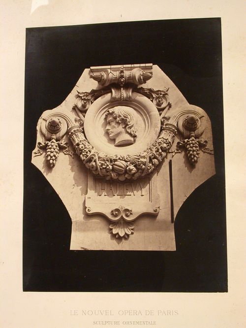
This unbound album comprises 42 plates and title pages and a list of plates (as follows): Le Nouvel Opéra de Paris. Sculpture ornementale Le Nouvel Opéra de Paris. Sculpture ornementale. Chapiteaux, tympans, panneaux, médaillons, masques, cartouches, pilastres, couronnements, clefs, frises, consoles, motifs divers d'ornementation par Charles Garnier, architecte, membre de l'Institut D et Cie, Paris, Librairie Générale de l'Architecture et des Travaux Publics, Ducher et Cie, Éditeurs, 51, rue des Écoles, 51, 1875. Table des Planches 1. - Médaillons - Tympans des arcades du rez-de-chaussée (façade principale). 2. - Cartouche couronnant les pilastres du grand vestibule. 3. - Cartouche servant d'applique sur les piliers du vestibule circulaire. 4. - Tables saillantes. - Galeries latérales du grand escalier. 5. - Table saillante. Pavillon de la descente à couvert. 6. - Table saillante. Vestibules octogones. 7. - Motifs de décoration sur les piliers du vestibule circulaire. 8. - Couronnement des grandes fenêtres. - Façade principale. 9. - Couronnement des portes du grand foyer. 10. - Couronnement desportes à l'extrémité des galeries latérales. 11. - Clef de la grande fenêtre. - Façade postérieure de la scène. 12. - Clef et tympan de la base du vestibule du contrôle. 13. - Clef des arcs dans la coupole du grand escalier. 14. - Clef de la porte. - Pavillon du chef de l'État. 15. - Consoles de chaque côté des oeils-de-boeuf au-dessus des baies de la loggia. 16. - Bas-relief de la partie supérieure de la voûte - vestibule octogone. 17. - Bas-reliefs de l'Attique. - Façade principale. 18. - Pilastres du grand foyer. - Arabesques et chapiteau. 19. - Colonnes du grand foyer. - Base et fut. (sic) 20. - Colonnes de la salle. - Base et fût. 21. - Colonnes des escaliers secondaires. - Fût et chapiteau. 22. - Chapiteau des pilastres du grand escalier. 23. - Chapiteau des colonnes du vestibule. - Pavillon du chef de l'État. 24. - Chapiteau des colonnes du vestibule circulaire. 25. - Chapiteau des colonnes du grand escalier. 26. - Chapiteau des colonnes supportant la 1re volée du grand escalier. 27. - Chapiteau des colonnes des baies de la loggia. - Façade principale. 28. - Chapiteau des colonnes du grand foyer. 29. - Chapiteau des pilastres intérieurs de la loggia. 30. - Chapiteau des colonnes et des pilastres de la salle. 31. - Amortissement des frontons des pavillons. - Façade principale. 32. - Chéneau de la grande coupole de la salle. 33. - Chéneau des façades latérales. 34. - Chéneau de la lanterne de la salle. 35. - Masques du vestibule circulaire. 36. - Masques du vestibule circulaire. 37. - Masques des consoles. - Baies de la loggia (façade principale). 38. - Masques du vestibule du contrôle. 39. - Masques des cheminées des bâtiments de l'administration. 40. - Frise et corniche de la scène. 41. - Frise de l'entablement. - Façade principale. 42. - Clef de voûte. - Galeries latérales. 43. - Clef de voûte. - Descente à couvert. 44. - Clef de voûte. - Galeries latérales. 45. - Clef de voûte. - Galeries latérales.
PH1979:0162.04:001
Description:
This unbound album comprises 42 plates and title pages and a list of plates (as follows): Le Nouvel Opéra de Paris. Sculpture ornementale Le Nouvel Opéra de Paris. Sculpture ornementale. Chapiteaux, tympans, panneaux, médaillons, masques, cartouches, pilastres, couronnements, clefs, frises, consoles, motifs divers d'ornementation par Charles Garnier, architecte, membre de l'Institut D et Cie, Paris, Librairie Générale de l'Architecture et des Travaux Publics, Ducher et Cie, Éditeurs, 51, rue des Écoles, 51, 1875. Table des Planches 1. - Médaillons - Tympans des arcades du rez-de-chaussée (façade principale). 2. - Cartouche couronnant les pilastres du grand vestibule. 3. - Cartouche servant d'applique sur les piliers du vestibule circulaire. 4. - Tables saillantes. - Galeries latérales du grand escalier. 5. - Table saillante. Pavillon de la descente à couvert. 6. - Table saillante. Vestibules octogones. 7. - Motifs de décoration sur les piliers du vestibule circulaire. 8. - Couronnement des grandes fenêtres. - Façade principale. 9. - Couronnement des portes du grand foyer. 10. - Couronnement desportes à l'extrémité des galeries latérales. 11. - Clef de la grande fenêtre. - Façade postérieure de la scène. 12. - Clef et tympan de la base du vestibule du contrôle. 13. - Clef des arcs dans la coupole du grand escalier. 14. - Clef de la porte. - Pavillon du chef de l'État. 15. - Consoles de chaque côté des oeils-de-boeuf au-dessus des baies de la loggia. 16. - Bas-relief de la partie supérieure de la voûte - vestibule octogone. 17. - Bas-reliefs de l'Attique. - Façade principale. 18. - Pilastres du grand foyer. - Arabesques et chapiteau. 19. - Colonnes du grand foyer. - Base et fut. (sic) 20. - Colonnes de la salle. - Base et fût. 21. - Colonnes des escaliers secondaires. - Fût et chapiteau. 22. - Chapiteau des pilastres du grand escalier. 23. - Chapiteau des colonnes du vestibule. - Pavillon du chef de l'État. 24. - Chapiteau des colonnes du vestibule circulaire. 25. - Chapiteau des colonnes du grand escalier. 26. - Chapiteau des colonnes supportant la 1re volée du grand escalier. 27. - Chapiteau des colonnes des baies de la loggia. - Façade principale. 28. - Chapiteau des colonnes du grand foyer. 29. - Chapiteau des pilastres intérieurs de la loggia. 30. - Chapiteau des colonnes et des pilastres de la salle. 31. - Amortissement des frontons des pavillons. - Façade principale. 32. - Chéneau de la grande coupole de la salle. 33. - Chéneau des façades latérales. 34. - Chéneau de la lanterne de la salle. 35. - Masques du vestibule circulaire. 36. - Masques du vestibule circulaire. 37. - Masques des consoles. - Baies de la loggia (façade principale). 38. - Masques du vestibule du contrôle. 39. - Masques des cheminées des bâtiments de l'administration. 40. - Frise et corniche de la scène. 41. - Frise de l'entablement. - Façade principale. 42. - Clef de voûte. - Galeries latérales. 43. - Clef de voûte. - Descente à couvert. 44. - Clef de voûte. - Galeries latérales. 45. - Clef de voûte. - Galeries latérales.
Personnes et institutions:
Sujet:
architecture, sculpture
architecture, sculpture
Date:
1875 or before
1875 or before
Titre:
Médaillons. - Tympans des arcades du rez-de-chaussée (façade principale)
Actions:
PH1979:0162.04:001
Description:
This unbound album comprises 42 plates and title pages and a list of plates (as follows): Le Nouvel Opéra de Paris. Sculpture ornementale Le Nouvel Opéra de Paris. Sculpture ornementale. Chapiteaux, tympans, panneaux, médaillons, masques, cartouches, pilastres, couronnements, clefs, frises, consoles, motifs divers d'ornementation par Charles Garnier, architecte, membre de l'Institut D et Cie, Paris, Librairie Générale de l'Architecture et des Travaux Publics, Ducher et Cie, Éditeurs, 51, rue des Écoles, 51, 1875. Table des Planches 1. - Médaillons - Tympans des arcades du rez-de-chaussée (façade principale). 2. - Cartouche couronnant les pilastres du grand vestibule. 3. - Cartouche servant d'applique sur les piliers du vestibule circulaire. 4. - Tables saillantes. - Galeries latérales du grand escalier. 5. - Table saillante. Pavillon de la descente à couvert. 6. - Table saillante. Vestibules octogones. 7. - Motifs de décoration sur les piliers du vestibule circulaire. 8. - Couronnement des grandes fenêtres. - Façade principale. 9. - Couronnement des portes du grand foyer. 10. - Couronnement desportes à l'extrémité des galeries latérales. 11. - Clef de la grande fenêtre. - Façade postérieure de la scène. 12. - Clef et tympan de la base du vestibule du contrôle. 13. - Clef des arcs dans la coupole du grand escalier. 14. - Clef de la porte. - Pavillon du chef de l'État. 15. - Consoles de chaque côté des oeils-de-boeuf au-dessus des baies de la loggia. 16. - Bas-relief de la partie supérieure de la voûte - vestibule octogone. 17. - Bas-reliefs de l'Attique. - Façade principale. 18. - Pilastres du grand foyer. - Arabesques et chapiteau. 19. - Colonnes du grand foyer. - Base et fut. (sic) 20. - Colonnes de la salle. - Base et fût. 21. - Colonnes des escaliers secondaires. - Fût et chapiteau. 22. - Chapiteau des pilastres du grand escalier. 23. - Chapiteau des colonnes du vestibule. - Pavillon du chef de l'État. 24. - Chapiteau des colonnes du vestibule circulaire. 25. - Chapiteau des colonnes du grand escalier. 26. - Chapiteau des colonnes supportant la 1re volée du grand escalier. 27. - Chapiteau des colonnes des baies de la loggia. - Façade principale. 28. - Chapiteau des colonnes du grand foyer. 29. - Chapiteau des pilastres intérieurs de la loggia. 30. - Chapiteau des colonnes et des pilastres de la salle. 31. - Amortissement des frontons des pavillons. - Façade principale. 32. - Chéneau de la grande coupole de la salle. 33. - Chéneau des façades latérales. 34. - Chéneau de la lanterne de la salle. 35. - Masques du vestibule circulaire. 36. - Masques du vestibule circulaire. 37. - Masques des consoles. - Baies de la loggia (façade principale). 38. - Masques du vestibule du contrôle. 39. - Masques des cheminées des bâtiments de l'administration. 40. - Frise et corniche de la scène. 41. - Frise de l'entablement. - Façade principale. 42. - Clef de voûte. - Galeries latérales. 43. - Clef de voûte. - Descente à couvert. 44. - Clef de voûte. - Galeries latérales. 45. - Clef de voûte. - Galeries latérales.
Classification:
photographies
photographies
Date:
1875 or before
1875 or before
Personnes et institutions:
Sujet:
architecture, sculpture
architecture, sculpture
Niveau de description archivistique:
Projet
Projet
Titre:
University Art Museum
University Art Museum
Numéro de référence:
AP143.S4.D65
Description:
File documents the unexecuted project for the University Art Museum, Long Beach, California. Material in this file was produced between 1986 and 1988. California State University, Long Beach (CSULB), commissioned Eisenman/Robertson Architects to design an art museum adjacent to the main campus entrance. The 67,500-square-foot building was to comprise four galleries, a black-box theater, an auditorium, a cafe, conference rooms, a library, offices, preparation spaces, and storage vaults. The project, sited on a 23-acre arboretum, included landscaping; terraced sculpture courtyards, botanical gardens, and a two-acre pond. Eisenman linked the northern and southern parts of the arboretum by an elevated public walkway through the museum. Sets of drawings were presented on 8 and 30 April, 2 June, and 5 Aug. In the first design phase Eisenman explores the cartographic figures which form the basis of his artificial excavation when superposed: a series of sketches establishes the analogical relationships which fix the relative scales of the plans and produce the superpositions; another series contextualizes the superposed figures by placing them within the museum site (DR1987:0859:087-090). The second phase concerns the building; the working model shows the building carved out of a square pit, from which spring an oil derrick and a reconstruction of a recreational pier (Rainbow Pier, 1920s) used here as circulatory bridge (DR1987:0859:160). In the third phase the architect systematizes his archeological procedure by using five significant cartographic dates - 1849, 1889, 1949, 1989, 2049 - each corresponding to a specific superposition (see DR1987:0859:274-277). In the fourth phase, Eisenman simplifies the superposition of 2049 to a few iconic colour-coded forms: ranch (green), ranch house (blue), campus site (red), and water forms (river and pond) (gold). Material for the fourth phase includes three relief models, four presentation drawings, and a model (property of the CSULB) (relief models: DR1987:0859:001-003; drawings: DR1987:0859:004-008). Eisenman "inhabits" his artifical archeology by detailed planning of interior spaces, and gives substance to the cartographic traces in a series of sketch sections, perspectives, and working models. Working models reveal how the central "canal" area gradually became the museum's access point (DR1987:0859:484-490); the museum, galleries, offices, and preparation areas are on one side of this deep cut, while the cafeteria and black-box theater are on the other. The upper level was to house offices, meeting rooms, and the library. File contains audiovisual material, conceptual drawings, design development drawings, presentation drawings, reference drawings, working drawings, photographic materials, and textual records.
Personnes et institutions:
Date:
1986-1988
1986-1988
Titre:
University Art Museum
Actions:
AP143.S4.D65
Description:
File documents the unexecuted project for the University Art Museum, Long Beach, California. Material in this file was produced between 1986 and 1988. California State University, Long Beach (CSULB), commissioned Eisenman/Robertson Architects to design an art museum adjacent to the main campus entrance. The 67,500-square-foot building was to comprise four galleries, a black-box theater, an auditorium, a cafe, conference rooms, a library, offices, preparation spaces, and storage vaults. The project, sited on a 23-acre arboretum, included landscaping; terraced sculpture courtyards, botanical gardens, and a two-acre pond. Eisenman linked the northern and southern parts of the arboretum by an elevated public walkway through the museum. Sets of drawings were presented on 8 and 30 April, 2 June, and 5 Aug. In the first design phase Eisenman explores the cartographic figures which form the basis of his artificial excavation when superposed: a series of sketches establishes the analogical relationships which fix the relative scales of the plans and produce the superpositions; another series contextualizes the superposed figures by placing them within the museum site (DR1987:0859:087-090). The second phase concerns the building; the working model shows the building carved out of a square pit, from which spring an oil derrick and a reconstruction of a recreational pier (Rainbow Pier, 1920s) used here as circulatory bridge (DR1987:0859:160). In the third phase the architect systematizes his archeological procedure by using five significant cartographic dates - 1849, 1889, 1949, 1989, 2049 - each corresponding to a specific superposition (see DR1987:0859:274-277). In the fourth phase, Eisenman simplifies the superposition of 2049 to a few iconic colour-coded forms: ranch (green), ranch house (blue), campus site (red), and water forms (river and pond) (gold). Material for the fourth phase includes three relief models, four presentation drawings, and a model (property of the CSULB) (relief models: DR1987:0859:001-003; drawings: DR1987:0859:004-008). Eisenman "inhabits" his artifical archeology by detailed planning of interior spaces, and gives substance to the cartographic traces in a series of sketch sections, perspectives, and working models. Working models reveal how the central "canal" area gradually became the museum's access point (DR1987:0859:484-490); the museum, galleries, offices, and preparation areas are on one side of this deep cut, while the cafeteria and black-box theater are on the other. The upper level was to house offices, meeting rooms, and the library. File contains audiovisual material, conceptual drawings, design development drawings, presentation drawings, reference drawings, working drawings, photographic materials, and textual records.
Niveau de description archivistique:
File 65
File 65
Date:
1986-1988
1986-1988
Personnes et institutions:
Classification:
dessins, photographies
dessins, photographies
Actions:
Numéro de référence:
PH1998:0013:001-048
Description:
- All of the projects in album PH1998:0013:001-048 were designed by Solomon Lisagor, some in collaboration with other architects, from 1923 through 1938 for various locations in Soviet Union. The photographs and magazine clippings show drawings and models for and views of twenty projects including: the Palace of Soviets, Moscow (10 pages); the Ordzhonikidze Sanatorium for the Ministry of the Oil Industry in Kislovodsk, Soviet Union (now Russia) (8 pages); the "Worker" RZhSKT [the "Worker" Worker's Housing Construction Cooperative Trust] in Saratov, Soviet Union (now Russia) (5 pages); the Limeny resort, Crimea, Soviet Union (now Ukraine) (4 pages); the Rostov Institute of Engineers of Transport [?], Rostov-on-Don, Soviet Union (now Russia) (3 pages); the House-commune of transitional type, Rostokino, Moscow (3 pages); a Building of People's Commissariat for Heavy Industry (Narkomtyazhprom), Moscow (3 pages); a Type F unit apartment, 8 Gogolevskii Boulevard, Moscow (2 pages); a development scheme for the southern coast of Crimea, Soviet Union (now Ukraine) (2 pages). Several other projects are represented on single album pages: a workers settlement in Kashira, a circus, and a Red Army Dormitory; a Sovtorgflot building, Arkhangel'sk, Soviet Union (now Russia); a typical experimental single-family house; prefabricated housing; a single-family house, a public rest room and two bus stops; a development scheme for the Ufa region, Bashkir Autonomous Soviet Socialist Republic, Soviet Union (now Ufa, Bashkortostan, Russia); and housing constructed from larger stone blocks [krupnye kamennye bloki]. One of the album pages is unused.
Personnes et institutions:
Sujet:
architecture
architecture
Date:
between 1923 and 1943
between 1923 and 1943
Titre:
Album of photographs and magazine clippings of projects by Solomon Lisagor, some designed in collaboration with other architects, Soviet Union (now in Russia and Ukraine)
Actions:
PH1998:0013:001-048
Description:
- All of the projects in album PH1998:0013:001-048 were designed by Solomon Lisagor, some in collaboration with other architects, from 1923 through 1938 for various locations in Soviet Union. The photographs and magazine clippings show drawings and models for and views of twenty projects including: the Palace of Soviets, Moscow (10 pages); the Ordzhonikidze Sanatorium for the Ministry of the Oil Industry in Kislovodsk, Soviet Union (now Russia) (8 pages); the "Worker" RZhSKT [the "Worker" Worker's Housing Construction Cooperative Trust] in Saratov, Soviet Union (now Russia) (5 pages); the Limeny resort, Crimea, Soviet Union (now Ukraine) (4 pages); the Rostov Institute of Engineers of Transport [?], Rostov-on-Don, Soviet Union (now Russia) (3 pages); the House-commune of transitional type, Rostokino, Moscow (3 pages); a Building of People's Commissariat for Heavy Industry (Narkomtyazhprom), Moscow (3 pages); a Type F unit apartment, 8 Gogolevskii Boulevard, Moscow (2 pages); a development scheme for the southern coast of Crimea, Soviet Union (now Ukraine) (2 pages). Several other projects are represented on single album pages: a workers settlement in Kashira, a circus, and a Red Army Dormitory; a Sovtorgflot building, Arkhangel'sk, Soviet Union (now Russia); a typical experimental single-family house; prefabricated housing; a single-family house, a public rest room and two bus stops; a development scheme for the Ufa region, Bashkir Autonomous Soviet Socialist Republic, Soviet Union (now Ufa, Bashkortostan, Russia); and housing constructed from larger stone blocks [krupnye kamennye bloki]. One of the album pages is unused.
Classification:
dessins, photographies
dessins, photographies
Date:
between 1923 and 1943
between 1923 and 1943
Personnes et institutions:
Sujet:
architecture
architecture
Classification:
archives
Niveau de description archivistique:
Fonds
archives
Niveau de description archivistique:
Fonds
Titre:
Fonds Gene Summers
Fonds Gene Summers
Numéro de référence:
AP114
Résumé:
The Gene Summers fonds documents primarily the later part of Gene Summers' career as an architect, developer, artist and art collector. Summer's early work with the Office of Mies van der Rohe and C.F. Murphy Associates is summarily represented by notes, sketches and photographs.
AP114
Résumé:
The Gene Summers fonds documents primarily the later part of Gene Summers' career as an architect, developer, artist and art collector. Summer's early work with the Office of Mies van der Rohe and C.F. Murphy Associates is summarily represented by notes, sketches and photographs.
Personnes et institutions:
Date:
1957 - 2004
1957 - 2004
Titre:
Fonds Gene Summers
Actions:
AP114
Résumé:
The Gene Summers fonds documents primarily the later part of Gene Summers' career as an architect, developer, artist and art collector. Summer's early work with the Office of Mies van der Rohe and C.F. Murphy Associates is summarily represented by notes, sketches and photographs.
Classification:
archives
Niveau de description archivistique:
Fonds
archives
Niveau de description archivistique:
Fonds
Date:
1957 - 2004
1957 - 2004
Personnes et institutions:
Classification:
dessins, documents textuels, oeuvres d'art
dessins, documents textuels, oeuvres d'art
Actions:
Numéro de référence:
DR1974:0002:010:001-048
Description:
- This album contains original designs - mostly preliminary drawings - by Charles and possibly Hubert Rohault de Fleury for theatres and miscellaneous projects, record drawings and prints of French, and perhaps Italian, theatres, and prints for a diverse collection of other French subjects. Drawings and prints for theatres include: traced plans, perhaps of Italian theatres; preliminary plans for theatres designed by Charles Rohault de Fleury; a plan of Théâtre de variétés, Paris, signed by the architect, Jacques Cellérier; prints of Théâtre de l'Odéon, Paris, designed by Charles de Wailly and Marie-Joseph Peyre; a print of Théâtre de la Porte Saint-Martin, Paris, designed by Nicolas Lenoir; a proposal for an opera house, Paris, by Hector Horeau with a plan and perspective; and an engraving of the inscription for the first stone of the Grand-Théâtre, Lyon, designed by Antoine-Marie Chenavard and Jean Pollet. The remaining prints in the album date from the 18th and 19th centuries and include: a competition entry by Louis-Pierre Baltard for a monument at Bordeaux dedicated to the triumphs of the Republican army and to peace; a stable for the Czarina commissioned by Peter I and designed by François Bruant; decorations by Victor Louis for the "fêtes de paix" of 1763 and the inauguration of an equestrian statue of Louis XV for the Théâtre italien dedicated to the Marquis de Marigny; a funerary temple by Louis-Jean Desprez dedicated to Voltaire; a stable with two manèges by Jean François de Neufforge; a competition entry for an obelisk for Pont-Neuf, Paris, by Thomas Pierre Baraguay; a plan and two engravings of the Cirque for the Confédération générale, 14 July 1790, on the Champ-de-Mars; an advertising flyer for Louis Ambroise Dubut's book, "Architecture civile: maison de ville et de campagne"; and a prospectus and print of the Néothermes, rue de la Victoire, Paris, designed by Jean Charles Bringol. Three design drawings are for two projects by Charles Rohault de Fleury - an iron arcade for boulevard du Temple, Paris, and a bathroom or public bath (DR1974:0002:010:013, DR1974:0002:010:014 and DR1974:0002:010:044). A finished drawing for entrance gates (DR1974:0002:010:047) and unidentified sketches and notes (DR1974:0002:010:019 - DR1974:0002:010:022) are by either Hubert or Charles Rohault de Fleury.
Personnes et institutions:
Sujet:
architecture, architecture temporaire, design d'intérieur, militaire, urbanisme
architecture, architecture temporaire, design d'intérieur, militaire, urbanisme
Date:
drawings executed ca. 1790-1868, manuscripts 1802-1868, printed 1717-1868
drawings executed ca. 1790-1868, manuscripts 1802-1868, printed 1717-1868
Titre:
Album of drawings, prints, and manuscripts of theatres and of French projects for buildings, monuments and temporary structures, and drawings and prints by Hubert and Charles Rohault de Fleury for theatres and miscellaneous projects
Actions:
DR1974:0002:010:001-048
Description:
- This album contains original designs - mostly preliminary drawings - by Charles and possibly Hubert Rohault de Fleury for theatres and miscellaneous projects, record drawings and prints of French, and perhaps Italian, theatres, and prints for a diverse collection of other French subjects. Drawings and prints for theatres include: traced plans, perhaps of Italian theatres; preliminary plans for theatres designed by Charles Rohault de Fleury; a plan of Théâtre de variétés, Paris, signed by the architect, Jacques Cellérier; prints of Théâtre de l'Odéon, Paris, designed by Charles de Wailly and Marie-Joseph Peyre; a print of Théâtre de la Porte Saint-Martin, Paris, designed by Nicolas Lenoir; a proposal for an opera house, Paris, by Hector Horeau with a plan and perspective; and an engraving of the inscription for the first stone of the Grand-Théâtre, Lyon, designed by Antoine-Marie Chenavard and Jean Pollet. The remaining prints in the album date from the 18th and 19th centuries and include: a competition entry by Louis-Pierre Baltard for a monument at Bordeaux dedicated to the triumphs of the Republican army and to peace; a stable for the Czarina commissioned by Peter I and designed by François Bruant; decorations by Victor Louis for the "fêtes de paix" of 1763 and the inauguration of an equestrian statue of Louis XV for the Théâtre italien dedicated to the Marquis de Marigny; a funerary temple by Louis-Jean Desprez dedicated to Voltaire; a stable with two manèges by Jean François de Neufforge; a competition entry for an obelisk for Pont-Neuf, Paris, by Thomas Pierre Baraguay; a plan and two engravings of the Cirque for the Confédération générale, 14 July 1790, on the Champ-de-Mars; an advertising flyer for Louis Ambroise Dubut's book, "Architecture civile: maison de ville et de campagne"; and a prospectus and print of the Néothermes, rue de la Victoire, Paris, designed by Jean Charles Bringol. Three design drawings are for two projects by Charles Rohault de Fleury - an iron arcade for boulevard du Temple, Paris, and a bathroom or public bath (DR1974:0002:010:013, DR1974:0002:010:014 and DR1974:0002:010:044). A finished drawing for entrance gates (DR1974:0002:010:047) and unidentified sketches and notes (DR1974:0002:010:019 - DR1974:0002:010:022) are by either Hubert or Charles Rohault de Fleury.
Classification:
dessins, documents textuels, oeuvres d'art
dessins, documents textuels, oeuvres d'art
Date:
drawings executed ca. 1790-1868, manuscripts 1802-1868, printed 1717-1868
drawings executed ca. 1790-1868, manuscripts 1802-1868, printed 1717-1868
Personnes et institutions:
Sujet:
architecture, architecture temporaire, design d'intérieur, militaire, urbanisme
architecture, architecture temporaire, design d'intérieur, militaire, urbanisme
Niveau de description archivistique:
Projet
Projet
Numéro de référence:
AP018.S1.1969.PR01
Description:
This project series documents the expansion of the Art Gallery of Ontario (AGO) in Toronto from 1969-1974. The office identified the project as number 69006. This project consisted of the vast expansion of the AGO that began in 1969, which largely came about due to a multi-million dollar donation from English sculpture Henry Moore. Most prominent in this project was the design and construction of the Henry Moore Sculpture Centre, a new gallery to house the extensive artworks of Henry Moore in the AGO’s collection. This included $15 million’s worth of art that Moore donated at the start of the project. The project was made up of two phases. The first included construction of the Henry Moore Sculpture Centre, the Sam and Ayala Zacks Wing, a link to the pre-existing Grange mansion, and updates to the art gallery’s finishes. The second phase proposed additional updates to existing finishes. By the end of this project, the architects had also added a public lounge, dining room and cafeteria, a members’ lounge, lecture areas (including the Henry Moore Lecture Hall), classrooms, and spaces for the gallery’s special services. The work was further divided into 4 physical areas of the art gallery (A, B, C and D) and the drawings for this project reflect this division. Before this work had been completed, a “Stage II” to the expansion had already been approved by the owners (Stage II is also included in this fonds, see AP018.S1.1972.PR08). In the documentation, this project was originally called the Henry Moore Sculpture Centre, Art Gallery of Ontario, Expansion Phases 1 and 2. However, as multiple stages to the expansion developed later on, this project eventually became known as the Stage I Expansion. While the project contract was originally given to John B. Parkin Associates, John C. Parkin continued the project under his new firm, Parkin Architects Planners, after parting ways with partner John B. Parkin in 1971. The project is recorded through drawings, textual records, and mounted photographs dating from 1968-1986. There are numerous original drawings showing the design development of the new galleries. Two presentation boards show photographs of the project model. The textual records consist of correspondence with contractors and clients, inspection and other site reports, specifications, contract data, consultancy records, schedules, change orders, financial documentation, conference reports, area calculations, research materials, detail planning records, and project notebooks. Box AP018.S1.1969.PR01.007 contains an index to the textual records, which was created by the office. This project series also contains one box of textual documentation that spans across multiple project series related to the AGO expansion within this fonds (see AP018.S1.1969.PR01.044). This includes press releases, newspaper articles, project proposals and studies, correspondence with Henry Moore, meeting minutes and reports.
Personnes et institutions:
Date:
1968-1986
1968-1986
Titre:
Henry Moore Sculpture Centre, Art Gallery of Ontario, Stage I Expansion, Toronto (1969-1974)
Actions:
AP018.S1.1969.PR01
Description:
This project series documents the expansion of the Art Gallery of Ontario (AGO) in Toronto from 1969-1974. The office identified the project as number 69006. This project consisted of the vast expansion of the AGO that began in 1969, which largely came about due to a multi-million dollar donation from English sculpture Henry Moore. Most prominent in this project was the design and construction of the Henry Moore Sculpture Centre, a new gallery to house the extensive artworks of Henry Moore in the AGO’s collection. This included $15 million’s worth of art that Moore donated at the start of the project. The project was made up of two phases. The first included construction of the Henry Moore Sculpture Centre, the Sam and Ayala Zacks Wing, a link to the pre-existing Grange mansion, and updates to the art gallery’s finishes. The second phase proposed additional updates to existing finishes. By the end of this project, the architects had also added a public lounge, dining room and cafeteria, a members’ lounge, lecture areas (including the Henry Moore Lecture Hall), classrooms, and spaces for the gallery’s special services. The work was further divided into 4 physical areas of the art gallery (A, B, C and D) and the drawings for this project reflect this division. Before this work had been completed, a “Stage II” to the expansion had already been approved by the owners (Stage II is also included in this fonds, see AP018.S1.1972.PR08). In the documentation, this project was originally called the Henry Moore Sculpture Centre, Art Gallery of Ontario, Expansion Phases 1 and 2. However, as multiple stages to the expansion developed later on, this project eventually became known as the Stage I Expansion. While the project contract was originally given to John B. Parkin Associates, John C. Parkin continued the project under his new firm, Parkin Architects Planners, after parting ways with partner John B. Parkin in 1971. The project is recorded through drawings, textual records, and mounted photographs dating from 1968-1986. There are numerous original drawings showing the design development of the new galleries. Two presentation boards show photographs of the project model. The textual records consist of correspondence with contractors and clients, inspection and other site reports, specifications, contract data, consultancy records, schedules, change orders, financial documentation, conference reports, area calculations, research materials, detail planning records, and project notebooks. Box AP018.S1.1969.PR01.007 contains an index to the textual records, which was created by the office. This project series also contains one box of textual documentation that spans across multiple project series related to the AGO expansion within this fonds (see AP018.S1.1969.PR01.044). This includes press releases, newspaper articles, project proposals and studies, correspondence with Henry Moore, meeting minutes and reports.
Niveau de description archivistique:
Project
Project
Date:
1968-1986
1968-1986
Personnes et institutions: