


12622 Results
Level of archival description:
Project
Project
Reference number:
AP178.S1.1980.PR01
Description:
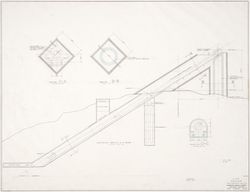
This project series document the Sede da Companhia Dom in Cologne, Germany. While the records were held in the office’s archives this project was assigned the number 1/80. The office assigned the date 1980 to this project. The project files document Siza's design for DOM company headquarter's architectural competition. Fifty architects were selected by a jury to propose a design. The client underlined the importance of having a striking visual impact while also putting emphasis on precision, security, protection and technological advancement. Requirements for the building included enough space for 250 employees and a covered parking lot for 50 vehicles. Siza's proposed design was a cylindrical inclined building with a cylindrical hole through the center. A circulation system with elevators, stairs and ramps inside and outside the office spaces was designed to create a " complex promenade architecturale"[1] . Siza's entry was not selected. Documenting this project are sketches, studies, design development drawings and competition drawings. Textual materials include competiton documentation. Of particular interest in this project series are the first computer drawings and coordinates used by Siza' office. [1] : Peter Testa "Álvaro Siza, " Birkhäuser Verlag, 1996.
AP178.S1.1980.PR01
Description:
This project series document the Sede da Companhia Dom in Cologne, Germany. While the records were held in the office’s archives this project was assigned the number 1/80. The office assigned the date 1980 to this project. The project files document Siza's design for DOM company headquarter's architectural competition. Fifty architects were selected by a jury to propose a design. The client underlined the importance of having a striking visual impact while also putting emphasis on precision, security, protection and technological advancement. Requirements for the building included enough space for 250 employees and a covered parking lot for 50 vehicles. Siza's proposed design was a cylindrical inclined building with a cylindrical hole through the center. A circulation system with elevators, stairs and ramps inside and outside the office spaces was designed to create a " complex promenade architecturale"[1] . Siza's entry was not selected. Documenting this project are sketches, studies, design development drawings and competition drawings. Textual materials include competiton documentation. Of particular interest in this project series are the first computer drawings and coordinates used by Siza' office. [1] : Peter Testa "Álvaro Siza, " Birkhäuser Verlag, 1996.
People:
Date:
1980-1981
1980-1981
Title:
Sede da Companhia Dom [Dom Company Headquarters], Cologne, Germany (1980)
Actions:
AP178.S1.1980.PR01
Description:
This project series document the Sede da Companhia Dom in Cologne, Germany. While the records were held in the office’s archives this project was assigned the number 1/80. The office assigned the date 1980 to this project. The project files document Siza's design for DOM company headquarter's architectural competition. Fifty architects were selected by a jury to propose a design. The client underlined the importance of having a striking visual impact while also putting emphasis on precision, security, protection and technological advancement. Requirements for the building included enough space for 250 employees and a covered parking lot for 50 vehicles. Siza's proposed design was a cylindrical inclined building with a cylindrical hole through the center. A circulation system with elevators, stairs and ramps inside and outside the office spaces was designed to create a " complex promenade architecturale"[1] . Siza's entry was not selected. Documenting this project are sketches, studies, design development drawings and competition drawings. Textual materials include competiton documentation. Of particular interest in this project series are the first computer drawings and coordinates used by Siza' office. [1] : Peter Testa "Álvaro Siza, " Birkhäuser Verlag, 1996.
Sede da Companhia Dom [Dom Company Headquarters], Cologne, Germany (1980)
Actions:
AP178.S1.1980.PR01
Description:
This project series document the Sede da Companhia Dom in Cologne, Germany. While the records were held in the office’s archives this project was assigned the number 1/80. The office assigned the date 1980 to this project. The project files document Siza's design for DOM company headquarter's architectural competition. Fifty architects were selected by a jury to propose a design. The client underlined the importance of having a striking visual impact while also putting emphasis on precision, security, protection and technological advancement. Requirements for the building included enough space for 250 employees and a covered parking lot for 50 vehicles. Siza's proposed design was a cylindrical inclined building with a cylindrical hole through the center. A circulation system with elevators, stairs and ramps inside and outside the office spaces was designed to create a " complex promenade architecturale"[1] . Siza's entry was not selected. Documenting this project are sketches, studies, design development drawings and competition drawings. Textual materials include competiton documentation. Of particular interest in this project series are the first computer drawings and coordinates used by Siza' office. [1] : Peter Testa "Álvaro Siza, " Birkhäuser Verlag, 1996.
Level of archival description:
Project
Project
Date:
1980-1981
1980-1981
People:
Level of archival description:
Project
Project
Reference number:
AP178.S1.1993.PR05
Description:
This project series documents the Laboratório Showroom Habitação Dimensione Fuoco in San Donà di Piave, Italy. While the records were held in the office’s archives this project was assigned the number 39/90. The office assigned the date 1993 to this project. The firm Dimensione Fuoco Vetroveneto commissioned Siza to design the extension of a building. The design proposed by Siza was a 3000 square metre triangular building, connecting with the existing structure with a courtyard and a boundary wall. It was intended that the cultural organization Circolo Architteture would occupy the space. The program included spaces for architectural conferences and exhibitions, a library and archives. Siza was also supposed to design a sculpture in the park near the building. It is not clear if the project was realized. Documenting this project are sketches, studies, design development drawings and working drawings. Textual materials include project documentation and correspondence. Photographic materials document the models, project site and construction work.
AP178.S1.1993.PR05
Description:
This project series documents the Laboratório Showroom Habitação Dimensione Fuoco in San Donà di Piave, Italy. While the records were held in the office’s archives this project was assigned the number 39/90. The office assigned the date 1993 to this project. The firm Dimensione Fuoco Vetroveneto commissioned Siza to design the extension of a building. The design proposed by Siza was a 3000 square metre triangular building, connecting with the existing structure with a courtyard and a boundary wall. It was intended that the cultural organization Circolo Architteture would occupy the space. The program included spaces for architectural conferences and exhibitions, a library and archives. Siza was also supposed to design a sculpture in the park near the building. It is not clear if the project was realized. Documenting this project are sketches, studies, design development drawings and working drawings. Textual materials include project documentation and correspondence. Photographic materials document the models, project site and construction work.
People:
Date:
1989-2012
1989-2012
Title:
Laboratório Showroom Habitação Dimensione Fuoco [Dimensione Fuocco Laboratory, Showroom and Housing], San Donà di Piave, Italy (1993)
Actions:
AP178.S1.1993.PR05
Description:
This project series documents the Laboratório Showroom Habitação Dimensione Fuoco in San Donà di Piave, Italy. While the records were held in the office’s archives this project was assigned the number 39/90. The office assigned the date 1993 to this project. The firm Dimensione Fuoco Vetroveneto commissioned Siza to design the extension of a building. The design proposed by Siza was a 3000 square metre triangular building, connecting with the existing structure with a courtyard and a boundary wall. It was intended that the cultural organization Circolo Architteture would occupy the space. The program included spaces for architectural conferences and exhibitions, a library and archives. Siza was also supposed to design a sculpture in the park near the building. It is not clear if the project was realized. Documenting this project are sketches, studies, design development drawings and working drawings. Textual materials include project documentation and correspondence. Photographic materials document the models, project site and construction work.
Laboratório Showroom Habitação Dimensione Fuoco [Dimensione Fuocco Laboratory, Showroom and Housing], San Donà di Piave, Italy (1993)
Actions:
AP178.S1.1993.PR05
Description:
This project series documents the Laboratório Showroom Habitação Dimensione Fuoco in San Donà di Piave, Italy. While the records were held in the office’s archives this project was assigned the number 39/90. The office assigned the date 1993 to this project. The firm Dimensione Fuoco Vetroveneto commissioned Siza to design the extension of a building. The design proposed by Siza was a 3000 square metre triangular building, connecting with the existing structure with a courtyard and a boundary wall. It was intended that the cultural organization Circolo Architteture would occupy the space. The program included spaces for architectural conferences and exhibitions, a library and archives. Siza was also supposed to design a sculpture in the park near the building. It is not clear if the project was realized. Documenting this project are sketches, studies, design development drawings and working drawings. Textual materials include project documentation and correspondence. Photographic materials document the models, project site and construction work.
Level of archival description:
Project
Project
Date:
1989-2012
1989-2012
People:
Form:
drawings, textual records
drawings, textual records
Reference number:
DR1995:0188:526-705
Description:
correspondence, architect's statement, proposals, building programme for Fun Palace Project, drafts of promotional material, clippings, report on Camden Pilot project, report on Fun Palace Project, notes on circulation, access, and systems, meeting notes, notes, minute of meetings of the Cybernetics Committee, draft articles with annotations, memoranda, draft survey, drafts and sketches of Fun Palace booklet, publications, cost estimate, sketch axonometric of service tower, brochures, questionnaires, certificate of incorporation for the Fun Palace, trust deeds, planning papers, application forms and site drawings of Children's Playground dated 1974, report on land redevelopment, and includes course outline dated 1980 for the Architectural Association
DR1995:0188:526-705
Description:
correspondence, architect's statement, proposals, building programme for Fun Palace Project, drafts of promotional material, clippings, report on Camden Pilot project, report on Fun Palace Project, notes on circulation, access, and systems, meeting notes, notes, minute of meetings of the Cybernetics Committee, draft articles with annotations, memoranda, draft survey, drafts and sketches of Fun Palace booklet, publications, cost estimate, sketch axonometric of service tower, brochures, questionnaires, certificate of incorporation for the Fun Palace, trust deeds, planning papers, application forms and site drawings of Children's Playground dated 1974, report on land redevelopment, and includes course outline dated 1980 for the Architectural Association
People:
Title:
Correspondence, architect's statement, proposals, building programme for Fun Palace Project
Actions:
DR1995:0188:526-705
Description:
correspondence, architect's statement, proposals, building programme for Fun Palace Project, drafts of promotional material, clippings, report on Camden Pilot project, report on Fun Palace Project, notes on circulation, access, and systems, meeting notes, notes, minute of meetings of the Cybernetics Committee, draft articles with annotations, memoranda, draft survey, drafts and sketches of Fun Palace booklet, publications, cost estimate, sketch axonometric of service tower, brochures, questionnaires, certificate of incorporation for the Fun Palace, trust deeds, planning papers, application forms and site drawings of Children's Playground dated 1974, report on land redevelopment, and includes course outline dated 1980 for the Architectural Association
Correspondence, architect's statement, proposals, building programme for Fun Palace Project
Actions:
DR1995:0188:526-705
Description:
correspondence, architect's statement, proposals, building programme for Fun Palace Project, drafts of promotional material, clippings, report on Camden Pilot project, report on Fun Palace Project, notes on circulation, access, and systems, meeting notes, notes, minute of meetings of the Cybernetics Committee, draft articles with annotations, memoranda, draft survey, drafts and sketches of Fun Palace booklet, publications, cost estimate, sketch axonometric of service tower, brochures, questionnaires, certificate of incorporation for the Fun Palace, trust deeds, planning papers, application forms and site drawings of Children's Playground dated 1974, report on land redevelopment, and includes course outline dated 1980 for the Architectural Association
Form:
drawings, textual records
drawings, textual records
People:
Level of archival description:
Series
Series
Title:
Digital material
Digital material
Actions:
Reference number:
AP165.S7
Description:
The Digital material series, 1980 – 2000, consists of 3398 digital files (2 GB) that relate to the engineering and invention of Hoberman’s patented transformable design, as well as the functions and activities of his company, Hoberman Associates, Inc. Material includes 1871 AutoCAD Drawing files, 952 AutoLISP files, 589 Microsoft Word Document files, and a number of text files, image files and spreadsheet files. The majority of the records date from the mid to late 1990’s. AutoCAD drawings relate to the design of art installations, toy products, and architectural structures, as well as industrial patents and production drawings that detail the manufacturing and assembly of parts. The series also includes scripts created by Hoberman for customized command within the AutoCAD environment. Company records of Hoberman Associates include correspondence with customers and clients, project descriptions, exhibition proposals, product manufacturing and pricing details, patent documentation, intellectual property information, agreements and legal documents concerning counterfeit toy products.
AP165.S7
Description:
The Digital material series, 1980 – 2000, consists of 3398 digital files (2 GB) that relate to the engineering and invention of Hoberman’s patented transformable design, as well as the functions and activities of his company, Hoberman Associates, Inc. Material includes 1871 AutoCAD Drawing files, 952 AutoLISP files, 589 Microsoft Word Document files, and a number of text files, image files and spreadsheet files. The majority of the records date from the mid to late 1990’s. AutoCAD drawings relate to the design of art installations, toy products, and architectural structures, as well as industrial patents and production drawings that detail the manufacturing and assembly of parts. The series also includes scripts created by Hoberman for customized command within the AutoCAD environment. Company records of Hoberman Associates include correspondence with customers and clients, project descriptions, exhibition proposals, product manufacturing and pricing details, patent documentation, intellectual property information, agreements and legal documents concerning counterfeit toy products.
People:
Date:
1980 - 2000
1980 - 2000
Title:
Digital material
Actions:
AP165.S7
Description:
The Digital material series, 1980 – 2000, consists of 3398 digital files (2 GB) that relate to the engineering and invention of Hoberman’s patented transformable design, as well as the functions and activities of his company, Hoberman Associates, Inc. Material includes 1871 AutoCAD Drawing files, 952 AutoLISP files, 589 Microsoft Word Document files, and a number of text files, image files and spreadsheet files. The majority of the records date from the mid to late 1990’s. AutoCAD drawings relate to the design of art installations, toy products, and architectural structures, as well as industrial patents and production drawings that detail the manufacturing and assembly of parts. The series also includes scripts created by Hoberman for customized command within the AutoCAD environment. Company records of Hoberman Associates include correspondence with customers and clients, project descriptions, exhibition proposals, product manufacturing and pricing details, patent documentation, intellectual property information, agreements and legal documents concerning counterfeit toy products.
Digital material
Actions:
AP165.S7
Description:
The Digital material series, 1980 – 2000, consists of 3398 digital files (2 GB) that relate to the engineering and invention of Hoberman’s patented transformable design, as well as the functions and activities of his company, Hoberman Associates, Inc. Material includes 1871 AutoCAD Drawing files, 952 AutoLISP files, 589 Microsoft Word Document files, and a number of text files, image files and spreadsheet files. The majority of the records date from the mid to late 1990’s. AutoCAD drawings relate to the design of art installations, toy products, and architectural structures, as well as industrial patents and production drawings that detail the manufacturing and assembly of parts. The series also includes scripts created by Hoberman for customized command within the AutoCAD environment. Company records of Hoberman Associates include correspondence with customers and clients, project descriptions, exhibition proposals, product manufacturing and pricing details, patent documentation, intellectual property information, agreements and legal documents concerning counterfeit toy products.
Level of archival description:
Series 7
Series 7
Date:
1980 - 2000
1980 - 2000
People:
Level of archival description:
Project
Project
Reference number:
AP018.S1.1962.PR03
Description:
This project series documents the design and construction of Ottawa Union Station in Ottawa, Ontario from 1962-1966. The office identified the project number as 6253. This project consisted of a 96,000 square foot train station building, platforms, canopies and site services. The building had two levels, which included a basement and two-storey ground floor. Passengers connected to the station platforms through the basement from the ground floor via a helicoidal ramp in the centre of the building. The passenger concourse was sheltered by a great steel truss roof that had 8 massive columns supporting it. The ground floor included bedrooms, offices, storage, and food and beverage areas. The building, owned by CN Railways, was commissioned by the National Capital Commission, who are recorded as the primary architect on the project, with E.W. Thrift as general manager, and with John B. Parkin Associates acting as consulting architects. The firm of John B. Parkin Associates was presented with a Silver Massey Medal in Architecture in 1967 for the design of this building. The project is recorded through reprographic copies of architectural and structural drawings dating from 1965-1966.
AP018.S1.1962.PR03
Description:
This project series documents the design and construction of Ottawa Union Station in Ottawa, Ontario from 1962-1966. The office identified the project number as 6253. This project consisted of a 96,000 square foot train station building, platforms, canopies and site services. The building had two levels, which included a basement and two-storey ground floor. Passengers connected to the station platforms through the basement from the ground floor via a helicoidal ramp in the centre of the building. The passenger concourse was sheltered by a great steel truss roof that had 8 massive columns supporting it. The ground floor included bedrooms, offices, storage, and food and beverage areas. The building, owned by CN Railways, was commissioned by the National Capital Commission, who are recorded as the primary architect on the project, with E.W. Thrift as general manager, and with John B. Parkin Associates acting as consulting architects. The firm of John B. Parkin Associates was presented with a Silver Massey Medal in Architecture in 1967 for the design of this building. The project is recorded through reprographic copies of architectural and structural drawings dating from 1965-1966.
People:
Date:
1965-1966
1965-1966
Title:
Ottawa Union Station, Ottawa, Ontario (1962-1966)
Actions:
AP018.S1.1962.PR03
Description:
This project series documents the design and construction of Ottawa Union Station in Ottawa, Ontario from 1962-1966. The office identified the project number as 6253. This project consisted of a 96,000 square foot train station building, platforms, canopies and site services. The building had two levels, which included a basement and two-storey ground floor. Passengers connected to the station platforms through the basement from the ground floor via a helicoidal ramp in the centre of the building. The passenger concourse was sheltered by a great steel truss roof that had 8 massive columns supporting it. The ground floor included bedrooms, offices, storage, and food and beverage areas. The building, owned by CN Railways, was commissioned by the National Capital Commission, who are recorded as the primary architect on the project, with E.W. Thrift as general manager, and with John B. Parkin Associates acting as consulting architects. The firm of John B. Parkin Associates was presented with a Silver Massey Medal in Architecture in 1967 for the design of this building. The project is recorded through reprographic copies of architectural and structural drawings dating from 1965-1966.
Ottawa Union Station, Ottawa, Ontario (1962-1966)
Actions:
AP018.S1.1962.PR03
Description:
This project series documents the design and construction of Ottawa Union Station in Ottawa, Ontario from 1962-1966. The office identified the project number as 6253. This project consisted of a 96,000 square foot train station building, platforms, canopies and site services. The building had two levels, which included a basement and two-storey ground floor. Passengers connected to the station platforms through the basement from the ground floor via a helicoidal ramp in the centre of the building. The passenger concourse was sheltered by a great steel truss roof that had 8 massive columns supporting it. The ground floor included bedrooms, offices, storage, and food and beverage areas. The building, owned by CN Railways, was commissioned by the National Capital Commission, who are recorded as the primary architect on the project, with E.W. Thrift as general manager, and with John B. Parkin Associates acting as consulting architects. The firm of John B. Parkin Associates was presented with a Silver Massey Medal in Architecture in 1967 for the design of this building. The project is recorded through reprographic copies of architectural and structural drawings dating from 1965-1966.
Level of archival description:
Project
Project
Date:
1965-1966
1965-1966
People:
Form:
webpages
webpages
Title:
Take a Closer Look
Take a Closer Look
Actions:
Summary:
The CCA’s collection of prints and drawings reveal ideas of architecture, the thinking process of architects, and the context they worked in.
Title:
Take a Closer Look
Actions:
Summary:
Take a Closer Look
Actions:
Summary:
The CCA’s collection of prints and drawings reveal ideas of architecture, the thinking process of architects, and the context they worked in.
Form:
webpages
webpages
Level of archival description:
Project
Project
Title:
Donmar
Donmar
Reference number:
AP144.S2.D53
Description:
File documents the unexecuted conversion of the Donmar rehearsal studio in Covent Garden, London, England, United Kingdom into an experimental theatre and late night meeting place. The client was the Fun Palace Trust ("Cedric Price Supplement", 'Architectural Design', vol. 40, (October 1970), 515) and negotiations for the conversion were undertaken with Donald Albery of New Theatre and Donmar Productions Limited. Movable platforms, furniture, and fittings were designed so that various seating and performance areas of different sizes could be created to accommodate a wide range of activities and entertainment of an impromptu nature. Survey drawings show the Donmar rehearsal studio and environs. Drawings for the conversion include plans, sections, axonometric projections, cutaway axonometric drawings showing the interior layout from two points of view, and conceptual sketches and perspectives of interior spaces in use. Axonometric drawings for fittings and furniture show platforms, a small stage, a chair/table, and a "conversation box". A drawing examines the sightlines of the converted interior by showing human figures in relationship with the movable units. Amended floor plans and sections show variations for the interior layout. Material in this file was produced between 1963 and 1964. File contains design development drawings and textual records.
AP144.S2.D53
Description:
File documents the unexecuted conversion of the Donmar rehearsal studio in Covent Garden, London, England, United Kingdom into an experimental theatre and late night meeting place. The client was the Fun Palace Trust ("Cedric Price Supplement", 'Architectural Design', vol. 40, (October 1970), 515) and negotiations for the conversion were undertaken with Donald Albery of New Theatre and Donmar Productions Limited. Movable platforms, furniture, and fittings were designed so that various seating and performance areas of different sizes could be created to accommodate a wide range of activities and entertainment of an impromptu nature. Survey drawings show the Donmar rehearsal studio and environs. Drawings for the conversion include plans, sections, axonometric projections, cutaway axonometric drawings showing the interior layout from two points of view, and conceptual sketches and perspectives of interior spaces in use. Axonometric drawings for fittings and furniture show platforms, a small stage, a chair/table, and a "conversation box". A drawing examines the sightlines of the converted interior by showing human figures in relationship with the movable units. Amended floor plans and sections show variations for the interior layout. Material in this file was produced between 1963 and 1964. File contains design development drawings and textual records.
People:
Date:
1963-1964
1963-1964
Title:
Donmar
Actions:
AP144.S2.D53
Description:
File documents the unexecuted conversion of the Donmar rehearsal studio in Covent Garden, London, England, United Kingdom into an experimental theatre and late night meeting place. The client was the Fun Palace Trust ("Cedric Price Supplement", 'Architectural Design', vol. 40, (October 1970), 515) and negotiations for the conversion were undertaken with Donald Albery of New Theatre and Donmar Productions Limited. Movable platforms, furniture, and fittings were designed so that various seating and performance areas of different sizes could be created to accommodate a wide range of activities and entertainment of an impromptu nature. Survey drawings show the Donmar rehearsal studio and environs. Drawings for the conversion include plans, sections, axonometric projections, cutaway axonometric drawings showing the interior layout from two points of view, and conceptual sketches and perspectives of interior spaces in use. Axonometric drawings for fittings and furniture show platforms, a small stage, a chair/table, and a "conversation box". A drawing examines the sightlines of the converted interior by showing human figures in relationship with the movable units. Amended floor plans and sections show variations for the interior layout. Material in this file was produced between 1963 and 1964. File contains design development drawings and textual records.
Donmar
Actions:
AP144.S2.D53
Description:
File documents the unexecuted conversion of the Donmar rehearsal studio in Covent Garden, London, England, United Kingdom into an experimental theatre and late night meeting place. The client was the Fun Palace Trust ("Cedric Price Supplement", 'Architectural Design', vol. 40, (October 1970), 515) and negotiations for the conversion were undertaken with Donald Albery of New Theatre and Donmar Productions Limited. Movable platforms, furniture, and fittings were designed so that various seating and performance areas of different sizes could be created to accommodate a wide range of activities and entertainment of an impromptu nature. Survey drawings show the Donmar rehearsal studio and environs. Drawings for the conversion include plans, sections, axonometric projections, cutaway axonometric drawings showing the interior layout from two points of view, and conceptual sketches and perspectives of interior spaces in use. Axonometric drawings for fittings and furniture show platforms, a small stage, a chair/table, and a "conversation box". A drawing examines the sightlines of the converted interior by showing human figures in relationship with the movable units. Amended floor plans and sections show variations for the interior layout. Material in this file was produced between 1963 and 1964. File contains design development drawings and textual records.
Level of archival description:
File 53
File 53
Date:
1963-1964
1963-1964
People:
Level of archival description:
Project
Project
Reference number:
AP166.S1.1991.PR2
Description:
This project series documents the project "Glass Station", a gas station constructed on an irregularly-shaped site at the entrance to the town of Oguni in Kumamoto Prefecture, Japan. The project was completed in 1993. The office, pumps, shop and work space of the service station are covered by an undulating canopy composed of asymmetrical concrete arches that form the boundaries of a lattice of pretensioned steel rods and aluminum channels into which panels of glass bonded to sheets of perforated stainless steel were inserted, sealed with polyester film, and secured with structural silicon. The project series is chiefly composed of design development drawings. It includes numbered sets of architectural drawings and structural drawings and some mechanical and electrical drawings. There is a set of unnumbered ink drawings and reproductions related to the geometry of the canopy. There are also some images of the canopy that are output from a computer file or files (wireframes and renderings). There is a small amount of textual material related to technical data and form finding for the canopy. The file also includes 2 study models. There are some graphic design documents for the name of the project and for the name "IDEX". Material in this file was created between 1990 and 1993.
AP166.S1.1991.PR2
Description:
This project series documents the project "Glass Station", a gas station constructed on an irregularly-shaped site at the entrance to the town of Oguni in Kumamoto Prefecture, Japan. The project was completed in 1993. The office, pumps, shop and work space of the service station are covered by an undulating canopy composed of asymmetrical concrete arches that form the boundaries of a lattice of pretensioned steel rods and aluminum channels into which panels of glass bonded to sheets of perforated stainless steel were inserted, sealed with polyester film, and secured with structural silicon. The project series is chiefly composed of design development drawings. It includes numbered sets of architectural drawings and structural drawings and some mechanical and electrical drawings. There is a set of unnumbered ink drawings and reproductions related to the geometry of the canopy. There are also some images of the canopy that are output from a computer file or files (wireframes and renderings). There is a small amount of textual material related to technical data and form finding for the canopy. The file also includes 2 study models. There are some graphic design documents for the name of the project and for the name "IDEX". Material in this file was created between 1990 and 1993.
People:
Date:
1990-1993
1990-1993
Title:
Glass Station, Oguni, Japan (1990-1993)
Actions:
AP166.S1.1991.PR2
Description:
This project series documents the project "Glass Station", a gas station constructed on an irregularly-shaped site at the entrance to the town of Oguni in Kumamoto Prefecture, Japan. The project was completed in 1993. The office, pumps, shop and work space of the service station are covered by an undulating canopy composed of asymmetrical concrete arches that form the boundaries of a lattice of pretensioned steel rods and aluminum channels into which panels of glass bonded to sheets of perforated stainless steel were inserted, sealed with polyester film, and secured with structural silicon. The project series is chiefly composed of design development drawings. It includes numbered sets of architectural drawings and structural drawings and some mechanical and electrical drawings. There is a set of unnumbered ink drawings and reproductions related to the geometry of the canopy. There are also some images of the canopy that are output from a computer file or files (wireframes and renderings). There is a small amount of textual material related to technical data and form finding for the canopy. The file also includes 2 study models. There are some graphic design documents for the name of the project and for the name "IDEX". Material in this file was created between 1990 and 1993.
Glass Station, Oguni, Japan (1990-1993)
Actions:
AP166.S1.1991.PR2
Description:
This project series documents the project "Glass Station", a gas station constructed on an irregularly-shaped site at the entrance to the town of Oguni in Kumamoto Prefecture, Japan. The project was completed in 1993. The office, pumps, shop and work space of the service station are covered by an undulating canopy composed of asymmetrical concrete arches that form the boundaries of a lattice of pretensioned steel rods and aluminum channels into which panels of glass bonded to sheets of perforated stainless steel were inserted, sealed with polyester film, and secured with structural silicon. The project series is chiefly composed of design development drawings. It includes numbered sets of architectural drawings and structural drawings and some mechanical and electrical drawings. There is a set of unnumbered ink drawings and reproductions related to the geometry of the canopy. There are also some images of the canopy that are output from a computer file or files (wireframes and renderings). There is a small amount of textual material related to technical data and form finding for the canopy. The file also includes 2 study models. There are some graphic design documents for the name of the project and for the name "IDEX". Material in this file was created between 1990 and 1993.
Level of archival description:
project
project
Date:
1990-1993
1990-1993
People:
Form:
exhibitions
exhibitions
Actions:
Description:
Myron Goldsmith’s architectural works show how an economy of means and a modest approach can generate a profoundly poetic expression. Myron Goldsmith: Poet of Structure reveals how the architect’s methods and ideas are formed, developed, and disseminated by drawing upon the body of notes, sketchbooks, and study documents found in the collection of Goldsmith’s personal(...)
Myron Goldsmith’s architectural works show how an economy of means and a modest approach can generate a profoundly poetic expression. Myron Goldsmith: Poet of Structure reveals how the architect’s methods and ideas are formed, developed, and disseminated by drawing upon the body of notes, sketchbooks, and study documents found in the collection of Goldsmith’s personal(...)
Location:
Main galleries
Main galleries
Date:
13 March 1991 to 2 June 1991
13 March 1991 to 2 June 1991
Title:
Myron Goldsmith: Poet of Structure
Actions:
Description:
Myron Goldsmith’s architectural works show how an economy of means and a modest approach can generate a profoundly poetic expression. Myron Goldsmith: Poet of Structure reveals how the architect’s methods and ideas are formed, developed, and disseminated by drawing upon the body of notes, sketchbooks, and study documents found in the collection of Goldsmith’s personal(...)
Myron Goldsmith: Poet of Structure
Actions:
Description:
Myron Goldsmith’s architectural works show how an economy of means and a modest approach can generate a profoundly poetic expression. Myron Goldsmith: Poet of Structure reveals how the architect’s methods and ideas are formed, developed, and disseminated by drawing upon the body of notes, sketchbooks, and study documents found in the collection of Goldsmith’s personal(...)
Form:
exhibitions
exhibitions
Date:
13 March 1991 to
2 June 1991
13 March 1991 to
2 June 1991
Location:
Main galleries
Main galleries
Form:
drawings
drawings
Actions:
Reference number:
AR1996:1001:231
Description:
- The inscribed titles on two drawings by Théophile Fahrland indicate that the subjects are a "tambour" [drum] (AR1996:1001:232) and details for a "tambour" (AR1996:1001:231) for Notre-Dame de Montréal. The subject of these drawings is identified as a "bearing wall [?]", since the definition of a "drum" - a vertical wall, either circular or polygonal in plan, that carries a dome - apparently does not apply in this case (Art and Architecture Thesaurus). Further research is required to determine the subject of these drawings more precisely.
AR1996:1001:231
Description:
- The inscribed titles on two drawings by Théophile Fahrland indicate that the subjects are a "tambour" [drum] (AR1996:1001:232) and details for a "tambour" (AR1996:1001:231) for Notre-Dame de Montréal. The subject of these drawings is identified as a "bearing wall [?]", since the definition of a "drum" - a vertical wall, either circular or polygonal in plan, that carries a dome - apparently does not apply in this case (Art and Architecture Thesaurus). Further research is required to determine the subject of these drawings more precisely.
People:
Subject:
architecture
architecture
Date:
contracted 20 September 1862
contracted 20 September 1862
Title:
Sections for a pilaster for a bearing wall [?] for Notre-Dame de Montréal for the renovations of the 1860s
Actions:
AR1996:1001:231
Description:
- The inscribed titles on two drawings by Théophile Fahrland indicate that the subjects are a "tambour" [drum] (AR1996:1001:232) and details for a "tambour" (AR1996:1001:231) for Notre-Dame de Montréal. The subject of these drawings is identified as a "bearing wall [?]", since the definition of a "drum" - a vertical wall, either circular or polygonal in plan, that carries a dome - apparently does not apply in this case (Art and Architecture Thesaurus). Further research is required to determine the subject of these drawings more precisely.
Sections for a pilaster for a bearing wall [?] for Notre-Dame de Montréal for the renovations of the 1860s
Actions:
AR1996:1001:231
Description:
- The inscribed titles on two drawings by Théophile Fahrland indicate that the subjects are a "tambour" [drum] (AR1996:1001:232) and details for a "tambour" (AR1996:1001:231) for Notre-Dame de Montréal. The subject of these drawings is identified as a "bearing wall [?]", since the definition of a "drum" - a vertical wall, either circular or polygonal in plan, that carries a dome - apparently does not apply in this case (Art and Architecture Thesaurus). Further research is required to determine the subject of these drawings more precisely.
Form:
drawings
drawings
Date:
contracted 20 September 1862
contracted 20 September 1862
People:
Subject:
architecture
architecture


