


12924 Results
Level of archival description:
Project
Project
Reference number:
AP143.S4.D14
Description:
File documents an executed project for House VI, a weekend/vacation house designed for Richard and Suzanne Frank for a six-acre lot at Great Hollow Road, Cornwall, Connecticut. The file also includes material for renovations to House VI undertaken in 1983, 1986, and 1989-1990. Material in this file was produced between 1971 and 1989. The 1,500 square foot plan of House VI comprises a kitchen, dining room, living room and study on the ground floor, and a bedroom and bathroom on the second floor. The most notable formal and compositional ambiguities of House VI are the two staircases, one green, and the other red and positioned on the ceiling. Documents include drawings by Eisenman concerning the geometric operations at the origin of House VI (DR1994:0134:055-067), conceptual drawings (DR1994:0134:001-068; DR1994:0134:086-130; DR1994:0134:131-160), numerous colour studies of the elevations (DR1994:0134:262-343), a presentation panel (DR1994:0134:521) notes (DR1994:0134:779-782), and a first set of working drawings and "check set," completed on 30 Aug. 1973, (DR1994:0134:667-689). Documents also include drawings for major revisions which occurred from 3 October 1973 through August 1974, photocopies of photographs of the house under construction (DR1994:0134:783-805), and a copy of the site survey (DR1994:0134:806). Planned and executed renovations to House VI began in 1983. Documents relating to unexecuted renovations and additions of 1983 includes drawings (DR1994:0134:604-615), a "bid set" and annotated copies (DR1994:0134:552 and DR1994:0134:554-570; copies: DR1994:0134:646-655), and a photocopy of the site plan indicating Eisenman's initial ideas (DR1994:0134:224). Documents relating to unexecuted renovations and additions of 1986 includes seven drawings (DR1994:0134:553 and DR1994:0134:628-633). House VI was extensively rebuilt between 1988 and 1990. The renovations included the replacement of the exterior plywood walls, the insertion of steel reinforcement, a new roof with skylights, the replacement of the original stucco by a coat of Finestone, the repainting of the interior, and the addition of a plexiglas barrier to the staircase. Documents relating to the renovations of 1988-90 include original and photocopied detail drawings, an interior paint schedule by Eisenman's office, correspondence, original and photocopied technical literature, an incomplete copy of the specifications, and a copy of the original survey map (identical to DR1994:0134:806). There are also numerous photographs of the building before, during and after renovation, one photograph of presentation axonometrics for House VI, and one photograph of Eisenman's office. Documents relating to a publication on House VI include: notes (DR1994:0134:807-853), the book mock-up (DR1994:0134:854-855), and fragments of the original coloured transformation diagrams (DR1994:0134:530-531). File contains conceptual drawings, including plans, axonometrics, and sections - many black felt-tip pen and/or coloured felt-tip pen on tracing paper; and reprographic copies - mostly photocopies on wove paper. Design development drawings include site plans, plans, elevations, sections, and axonometrics - some graphite and/or coloured pencil on tracing paper and some pen and black ink and/or graphite on tracing vellum; and reprographic copies - some photocopies on wove paper and some sepia prints on mylar. Schematic drawings include site plans, plans, elevations, and sections - all pen and black ink on mylar; and reprographic copies - many blackline prints on wove paper. Working drawings include site plans, plans, elevations, sections, electrical drawings, HVAC drawings, structural drawings, and detail drawings - some coloured pencil on blueline prints on wove paper; and reprographic copies - mostly blueline prints on wove paper. Presentation drawings include plans, elevations, and axonometrics - some pen and black ink and/or transparent coloured adhesive film on mylar and some translucent adhesive coloured film on cardboard; and reprographic copies - mostly photocopies on wove paper. Model includes one finished model - grey, white, and silver paint on wood and Fome-Cor with plastic sheets. Notes and documents include manuscripts - mostly black felt-tip pen on wove paper; reprographic copies - mostly photocopies on wove paper; and a land surveyor plan - one blueline print on wove paper. Book project includes layout drawings - some black felt-tip pen on ruled paper; reprographic copies - all photocopies on wove paper; manuscripts - mostly black felt-tip pen on wove or ruled paper; one sample piece of grey cardboard used as backing for some of the presentation drawings; and sets of drawings in the form of book dummies - mostly pen and coloured ink and/or black felt-tip pen on photocopies on wove paper. Detail drawings include elevations, sections, details - mostly graphite on tracing paper. The linear cm of documents includes sets, reprographic copies and manuscripts. Notes and documents include elevations, sections, and details - some graphite on photocopies on wove paper; two sets of drawing copies, some with changes - mostly photocopies on wove paper; reprographic copies - mostly photocopies on wove paper; manuscripts - many graphite on wove paper; ephemera includes trade pamphlets; and photographs include colour images of House X prior to and during one of the renovations.
AP143.S4.D14
Description:
File documents an executed project for House VI, a weekend/vacation house designed for Richard and Suzanne Frank for a six-acre lot at Great Hollow Road, Cornwall, Connecticut. The file also includes material for renovations to House VI undertaken in 1983, 1986, and 1989-1990. Material in this file was produced between 1971 and 1989. The 1,500 square foot plan of House VI comprises a kitchen, dining room, living room and study on the ground floor, and a bedroom and bathroom on the second floor. The most notable formal and compositional ambiguities of House VI are the two staircases, one green, and the other red and positioned on the ceiling. Documents include drawings by Eisenman concerning the geometric operations at the origin of House VI (DR1994:0134:055-067), conceptual drawings (DR1994:0134:001-068; DR1994:0134:086-130; DR1994:0134:131-160), numerous colour studies of the elevations (DR1994:0134:262-343), a presentation panel (DR1994:0134:521) notes (DR1994:0134:779-782), and a first set of working drawings and "check set," completed on 30 Aug. 1973, (DR1994:0134:667-689). Documents also include drawings for major revisions which occurred from 3 October 1973 through August 1974, photocopies of photographs of the house under construction (DR1994:0134:783-805), and a copy of the site survey (DR1994:0134:806). Planned and executed renovations to House VI began in 1983. Documents relating to unexecuted renovations and additions of 1983 includes drawings (DR1994:0134:604-615), a "bid set" and annotated copies (DR1994:0134:552 and DR1994:0134:554-570; copies: DR1994:0134:646-655), and a photocopy of the site plan indicating Eisenman's initial ideas (DR1994:0134:224). Documents relating to unexecuted renovations and additions of 1986 includes seven drawings (DR1994:0134:553 and DR1994:0134:628-633). House VI was extensively rebuilt between 1988 and 1990. The renovations included the replacement of the exterior plywood walls, the insertion of steel reinforcement, a new roof with skylights, the replacement of the original stucco by a coat of Finestone, the repainting of the interior, and the addition of a plexiglas barrier to the staircase. Documents relating to the renovations of 1988-90 include original and photocopied detail drawings, an interior paint schedule by Eisenman's office, correspondence, original and photocopied technical literature, an incomplete copy of the specifications, and a copy of the original survey map (identical to DR1994:0134:806). There are also numerous photographs of the building before, during and after renovation, one photograph of presentation axonometrics for House VI, and one photograph of Eisenman's office. Documents relating to a publication on House VI include: notes (DR1994:0134:807-853), the book mock-up (DR1994:0134:854-855), and fragments of the original coloured transformation diagrams (DR1994:0134:530-531). File contains conceptual drawings, including plans, axonometrics, and sections - many black felt-tip pen and/or coloured felt-tip pen on tracing paper; and reprographic copies - mostly photocopies on wove paper. Design development drawings include site plans, plans, elevations, sections, and axonometrics - some graphite and/or coloured pencil on tracing paper and some pen and black ink and/or graphite on tracing vellum; and reprographic copies - some photocopies on wove paper and some sepia prints on mylar. Schematic drawings include site plans, plans, elevations, and sections - all pen and black ink on mylar; and reprographic copies - many blackline prints on wove paper. Working drawings include site plans, plans, elevations, sections, electrical drawings, HVAC drawings, structural drawings, and detail drawings - some coloured pencil on blueline prints on wove paper; and reprographic copies - mostly blueline prints on wove paper. Presentation drawings include plans, elevations, and axonometrics - some pen and black ink and/or transparent coloured adhesive film on mylar and some translucent adhesive coloured film on cardboard; and reprographic copies - mostly photocopies on wove paper. Model includes one finished model - grey, white, and silver paint on wood and Fome-Cor with plastic sheets. Notes and documents include manuscripts - mostly black felt-tip pen on wove paper; reprographic copies - mostly photocopies on wove paper; and a land surveyor plan - one blueline print on wove paper. Book project includes layout drawings - some black felt-tip pen on ruled paper; reprographic copies - all photocopies on wove paper; manuscripts - mostly black felt-tip pen on wove or ruled paper; one sample piece of grey cardboard used as backing for some of the presentation drawings; and sets of drawings in the form of book dummies - mostly pen and coloured ink and/or black felt-tip pen on photocopies on wove paper. Detail drawings include elevations, sections, details - mostly graphite on tracing paper. The linear cm of documents includes sets, reprographic copies and manuscripts. Notes and documents include elevations, sections, and details - some graphite on photocopies on wove paper; two sets of drawing copies, some with changes - mostly photocopies on wove paper; reprographic copies - mostly photocopies on wove paper; manuscripts - many graphite on wove paper; ephemera includes trade pamphlets; and photographs include colour images of House X prior to and during one of the renovations.
People:
Date:
1971-1989
1971-1989
Title:
House VI, Cornwall, Connecticut
Actions:
AP143.S4.D14
Description:
File documents an executed project for House VI, a weekend/vacation house designed for Richard and Suzanne Frank for a six-acre lot at Great Hollow Road, Cornwall, Connecticut. The file also includes material for renovations to House VI undertaken in 1983, 1986, and 1989-1990. Material in this file was produced between 1971 and 1989. The 1,500 square foot plan of House VI comprises a kitchen, dining room, living room and study on the ground floor, and a bedroom and bathroom on the second floor. The most notable formal and compositional ambiguities of House VI are the two staircases, one green, and the other red and positioned on the ceiling. Documents include drawings by Eisenman concerning the geometric operations at the origin of House VI (DR1994:0134:055-067), conceptual drawings (DR1994:0134:001-068; DR1994:0134:086-130; DR1994:0134:131-160), numerous colour studies of the elevations (DR1994:0134:262-343), a presentation panel (DR1994:0134:521) notes (DR1994:0134:779-782), and a first set of working drawings and "check set," completed on 30 Aug. 1973, (DR1994:0134:667-689). Documents also include drawings for major revisions which occurred from 3 October 1973 through August 1974, photocopies of photographs of the house under construction (DR1994:0134:783-805), and a copy of the site survey (DR1994:0134:806). Planned and executed renovations to House VI began in 1983. Documents relating to unexecuted renovations and additions of 1983 includes drawings (DR1994:0134:604-615), a "bid set" and annotated copies (DR1994:0134:552 and DR1994:0134:554-570; copies: DR1994:0134:646-655), and a photocopy of the site plan indicating Eisenman's initial ideas (DR1994:0134:224). Documents relating to unexecuted renovations and additions of 1986 includes seven drawings (DR1994:0134:553 and DR1994:0134:628-633). House VI was extensively rebuilt between 1988 and 1990. The renovations included the replacement of the exterior plywood walls, the insertion of steel reinforcement, a new roof with skylights, the replacement of the original stucco by a coat of Finestone, the repainting of the interior, and the addition of a plexiglas barrier to the staircase. Documents relating to the renovations of 1988-90 include original and photocopied detail drawings, an interior paint schedule by Eisenman's office, correspondence, original and photocopied technical literature, an incomplete copy of the specifications, and a copy of the original survey map (identical to DR1994:0134:806). There are also numerous photographs of the building before, during and after renovation, one photograph of presentation axonometrics for House VI, and one photograph of Eisenman's office. Documents relating to a publication on House VI include: notes (DR1994:0134:807-853), the book mock-up (DR1994:0134:854-855), and fragments of the original coloured transformation diagrams (DR1994:0134:530-531). File contains conceptual drawings, including plans, axonometrics, and sections - many black felt-tip pen and/or coloured felt-tip pen on tracing paper; and reprographic copies - mostly photocopies on wove paper. Design development drawings include site plans, plans, elevations, sections, and axonometrics - some graphite and/or coloured pencil on tracing paper and some pen and black ink and/or graphite on tracing vellum; and reprographic copies - some photocopies on wove paper and some sepia prints on mylar. Schematic drawings include site plans, plans, elevations, and sections - all pen and black ink on mylar; and reprographic copies - many blackline prints on wove paper. Working drawings include site plans, plans, elevations, sections, electrical drawings, HVAC drawings, structural drawings, and detail drawings - some coloured pencil on blueline prints on wove paper; and reprographic copies - mostly blueline prints on wove paper. Presentation drawings include plans, elevations, and axonometrics - some pen and black ink and/or transparent coloured adhesive film on mylar and some translucent adhesive coloured film on cardboard; and reprographic copies - mostly photocopies on wove paper. Model includes one finished model - grey, white, and silver paint on wood and Fome-Cor with plastic sheets. Notes and documents include manuscripts - mostly black felt-tip pen on wove paper; reprographic copies - mostly photocopies on wove paper; and a land surveyor plan - one blueline print on wove paper. Book project includes layout drawings - some black felt-tip pen on ruled paper; reprographic copies - all photocopies on wove paper; manuscripts - mostly black felt-tip pen on wove or ruled paper; one sample piece of grey cardboard used as backing for some of the presentation drawings; and sets of drawings in the form of book dummies - mostly pen and coloured ink and/or black felt-tip pen on photocopies on wove paper. Detail drawings include elevations, sections, details - mostly graphite on tracing paper. The linear cm of documents includes sets, reprographic copies and manuscripts. Notes and documents include elevations, sections, and details - some graphite on photocopies on wove paper; two sets of drawing copies, some with changes - mostly photocopies on wove paper; reprographic copies - mostly photocopies on wove paper; manuscripts - many graphite on wove paper; ephemera includes trade pamphlets; and photographs include colour images of House X prior to and during one of the renovations.
House VI, Cornwall, Connecticut
Actions:
AP143.S4.D14
Description:
File documents an executed project for House VI, a weekend/vacation house designed for Richard and Suzanne Frank for a six-acre lot at Great Hollow Road, Cornwall, Connecticut. The file also includes material for renovations to House VI undertaken in 1983, 1986, and 1989-1990. Material in this file was produced between 1971 and 1989. The 1,500 square foot plan of House VI comprises a kitchen, dining room, living room and study on the ground floor, and a bedroom and bathroom on the second floor. The most notable formal and compositional ambiguities of House VI are the two staircases, one green, and the other red and positioned on the ceiling. Documents include drawings by Eisenman concerning the geometric operations at the origin of House VI (DR1994:0134:055-067), conceptual drawings (DR1994:0134:001-068; DR1994:0134:086-130; DR1994:0134:131-160), numerous colour studies of the elevations (DR1994:0134:262-343), a presentation panel (DR1994:0134:521) notes (DR1994:0134:779-782), and a first set of working drawings and "check set," completed on 30 Aug. 1973, (DR1994:0134:667-689). Documents also include drawings for major revisions which occurred from 3 October 1973 through August 1974, photocopies of photographs of the house under construction (DR1994:0134:783-805), and a copy of the site survey (DR1994:0134:806). Planned and executed renovations to House VI began in 1983. Documents relating to unexecuted renovations and additions of 1983 includes drawings (DR1994:0134:604-615), a "bid set" and annotated copies (DR1994:0134:552 and DR1994:0134:554-570; copies: DR1994:0134:646-655), and a photocopy of the site plan indicating Eisenman's initial ideas (DR1994:0134:224). Documents relating to unexecuted renovations and additions of 1986 includes seven drawings (DR1994:0134:553 and DR1994:0134:628-633). House VI was extensively rebuilt between 1988 and 1990. The renovations included the replacement of the exterior plywood walls, the insertion of steel reinforcement, a new roof with skylights, the replacement of the original stucco by a coat of Finestone, the repainting of the interior, and the addition of a plexiglas barrier to the staircase. Documents relating to the renovations of 1988-90 include original and photocopied detail drawings, an interior paint schedule by Eisenman's office, correspondence, original and photocopied technical literature, an incomplete copy of the specifications, and a copy of the original survey map (identical to DR1994:0134:806). There are also numerous photographs of the building before, during and after renovation, one photograph of presentation axonometrics for House VI, and one photograph of Eisenman's office. Documents relating to a publication on House VI include: notes (DR1994:0134:807-853), the book mock-up (DR1994:0134:854-855), and fragments of the original coloured transformation diagrams (DR1994:0134:530-531). File contains conceptual drawings, including plans, axonometrics, and sections - many black felt-tip pen and/or coloured felt-tip pen on tracing paper; and reprographic copies - mostly photocopies on wove paper. Design development drawings include site plans, plans, elevations, sections, and axonometrics - some graphite and/or coloured pencil on tracing paper and some pen and black ink and/or graphite on tracing vellum; and reprographic copies - some photocopies on wove paper and some sepia prints on mylar. Schematic drawings include site plans, plans, elevations, and sections - all pen and black ink on mylar; and reprographic copies - many blackline prints on wove paper. Working drawings include site plans, plans, elevations, sections, electrical drawings, HVAC drawings, structural drawings, and detail drawings - some coloured pencil on blueline prints on wove paper; and reprographic copies - mostly blueline prints on wove paper. Presentation drawings include plans, elevations, and axonometrics - some pen and black ink and/or transparent coloured adhesive film on mylar and some translucent adhesive coloured film on cardboard; and reprographic copies - mostly photocopies on wove paper. Model includes one finished model - grey, white, and silver paint on wood and Fome-Cor with plastic sheets. Notes and documents include manuscripts - mostly black felt-tip pen on wove paper; reprographic copies - mostly photocopies on wove paper; and a land surveyor plan - one blueline print on wove paper. Book project includes layout drawings - some black felt-tip pen on ruled paper; reprographic copies - all photocopies on wove paper; manuscripts - mostly black felt-tip pen on wove or ruled paper; one sample piece of grey cardboard used as backing for some of the presentation drawings; and sets of drawings in the form of book dummies - mostly pen and coloured ink and/or black felt-tip pen on photocopies on wove paper. Detail drawings include elevations, sections, details - mostly graphite on tracing paper. The linear cm of documents includes sets, reprographic copies and manuscripts. Notes and documents include elevations, sections, and details - some graphite on photocopies on wove paper; two sets of drawing copies, some with changes - mostly photocopies on wove paper; reprographic copies - mostly photocopies on wove paper; manuscripts - many graphite on wove paper; ephemera includes trade pamphlets; and photographs include colour images of House X prior to and during one of the renovations.
Level of archival description:
File 14
File 14
Date:
1971-1989
1971-1989
People:
Form:
photographs
photographs
Actions:
Reference number:
ARCH275459
Description:
2 binders labeled "Miscellaneous," contains slides of various architectural projects, exhibtions, sites, and studies. Includes: Art Gallery of Ontario, Center for Inter-American Relations installation, Crysler Building, Regional Municipality of York, Scarborough Town Centre, Campbell House moving techniques, Ontario Trade and Industry Centre Analysis of Site, site photographs, mock-up model, construction phase, St James Town, Penthouse-Canada Square, Cox Townhouses- Site Study, Badr Touristic City Site, China Hotels Study, Site Study for Judicial Complex, Ottawa, Wellington St. West, Site Development, views of sites in Egypt, Hotel Youville,
ARCH275459
Description:
2 binders labeled "Miscellaneous," contains slides of various architectural projects, exhibtions, sites, and studies. Includes: Art Gallery of Ontario, Center for Inter-American Relations installation, Crysler Building, Regional Municipality of York, Scarborough Town Centre, Campbell House moving techniques, Ontario Trade and Industry Centre Analysis of Site, site photographs, mock-up model, construction phase, St James Town, Penthouse-Canada Square, Cox Townhouses- Site Study, Badr Touristic City Site, China Hotels Study, Site Study for Judicial Complex, Ottawa, Wellington St. West, Site Development, views of sites in Egypt, Hotel Youville,
People:
Date:
ca. 1974-1995
ca. 1974-1995
Title:
Slides of various architectural projects, exhibtions, sites, and studies
Actions:
ARCH275459
Description:
2 binders labeled "Miscellaneous," contains slides of various architectural projects, exhibtions, sites, and studies. Includes: Art Gallery of Ontario, Center for Inter-American Relations installation, Crysler Building, Regional Municipality of York, Scarborough Town Centre, Campbell House moving techniques, Ontario Trade and Industry Centre Analysis of Site, site photographs, mock-up model, construction phase, St James Town, Penthouse-Canada Square, Cox Townhouses- Site Study, Badr Touristic City Site, China Hotels Study, Site Study for Judicial Complex, Ottawa, Wellington St. West, Site Development, views of sites in Egypt, Hotel Youville,
Slides of various architectural projects, exhibtions, sites, and studies
Actions:
ARCH275459
Description:
2 binders labeled "Miscellaneous," contains slides of various architectural projects, exhibtions, sites, and studies. Includes: Art Gallery of Ontario, Center for Inter-American Relations installation, Crysler Building, Regional Municipality of York, Scarborough Town Centre, Campbell House moving techniques, Ontario Trade and Industry Centre Analysis of Site, site photographs, mock-up model, construction phase, St James Town, Penthouse-Canada Square, Cox Townhouses- Site Study, Badr Touristic City Site, China Hotels Study, Site Study for Judicial Complex, Ottawa, Wellington St. West, Site Development, views of sites in Egypt, Hotel Youville,
Form:
photographs
photographs
Date:
ca. 1974-1995
ca. 1974-1995
People:
Form:
textual records
Quantity:
279 sheet(s)
textual records
Quantity:
279 sheet(s)
Actions:
Reference number:
ARCH193536
Description:
Notes on sayings and teachings of Mies van der Rohe and others; small sketch and accompanying notes by Mies van der Rohe; sketches of still-life and model compositions; plans, perspectives, elevations, axonometric views and structural details including some for identified projects such as Home Federal Savings and Loan, Des Moines, Iowa (1959-62); Federal Center, Chicago (1959-73); Ron Bacardi y Compañia Administration Building, Mexico City (1958-61); Office Building for United States Consulate, Sao Paulo, Brazil (1957-62); New National Gallery, Berlin (1962-68). Accompanied by notes added by Phyllis Lambert (November 2000).
ARCH193536
Description:
Notes on sayings and teachings of Mies van der Rohe and others; small sketch and accompanying notes by Mies van der Rohe; sketches of still-life and model compositions; plans, perspectives, elevations, axonometric views and structural details including some for identified projects such as Home Federal Savings and Loan, Des Moines, Iowa (1959-62); Federal Center, Chicago (1959-73); Ron Bacardi y Compañia Administration Building, Mexico City (1958-61); Office Building for United States Consulate, Sao Paulo, Brazil (1957-62); New National Gallery, Berlin (1962-68). Accompanied by notes added by Phyllis Lambert (November 2000).
People:
Date:
circa 1959 - 2000
circa 1959 - 2000
Title:
Notes on sayings and teachings of Mies van der Rohe and others
Actions:
ARCH193536
Description:
Notes on sayings and teachings of Mies van der Rohe and others; small sketch and accompanying notes by Mies van der Rohe; sketches of still-life and model compositions; plans, perspectives, elevations, axonometric views and structural details including some for identified projects such as Home Federal Savings and Loan, Des Moines, Iowa (1959-62); Federal Center, Chicago (1959-73); Ron Bacardi y Compañia Administration Building, Mexico City (1958-61); Office Building for United States Consulate, Sao Paulo, Brazil (1957-62); New National Gallery, Berlin (1962-68). Accompanied by notes added by Phyllis Lambert (November 2000).
Notes on sayings and teachings of Mies van der Rohe and others
Actions:
ARCH193536
Description:
Notes on sayings and teachings of Mies van der Rohe and others; small sketch and accompanying notes by Mies van der Rohe; sketches of still-life and model compositions; plans, perspectives, elevations, axonometric views and structural details including some for identified projects such as Home Federal Savings and Loan, Des Moines, Iowa (1959-62); Federal Center, Chicago (1959-73); Ron Bacardi y Compañia Administration Building, Mexico City (1958-61); Office Building for United States Consulate, Sao Paulo, Brazil (1957-62); New National Gallery, Berlin (1962-68). Accompanied by notes added by Phyllis Lambert (November 2000).
Form:
textual records
Quantity:
279 sheet(s)
textual records
Quantity:
279 sheet(s)
Date:
circa 1959 - 2000
circa 1959 - 2000
People:
Form:
works of art
works of art
Actions:
Reference number:
DR1987:0342
Description:
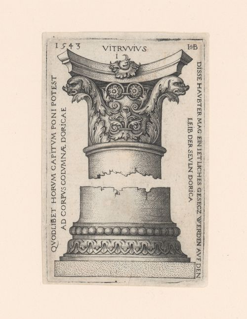
- This engraving depicts a design for an order of architecture showing the capital and the base. Although the inscriptions refer to "DORICA[E]", this is not one of the traditional orders of architecture: the acanthus leaves on the capital suggest a Corinthian model while other details, such as the dolphin heads, suggest a more personal interpretation. - This print is one of a set of four prints of capitals and bases which were engraved by Hans Sebald Beham. Patricia Condon suggests that these prints were made for a general audience rather than for architects ('Ornament and Architecture', 29). Three of the prints in the CCA collection are from the collection of the Ducs d'Arenburg, while the provenance of this print is unknown.
DR1987:0342
Description:
- This engraving depicts a design for an order of architecture showing the capital and the base. Although the inscriptions refer to "DORICA[E]", this is not one of the traditional orders of architecture: the acanthus leaves on the capital suggest a Corinthian model while other details, such as the dolphin heads, suggest a more personal interpretation. - This print is one of a set of four prints of capitals and bases which were engraved by Hans Sebald Beham. Patricia Condon suggests that these prints were made for a general audience rather than for architects ('Ornament and Architecture', 29). Three of the prints in the CCA collection are from the collection of the Ducs d'Arenburg, while the provenance of this print is unknown.
People:
Subject:
architecture
architecture
Date:
1543
1543
Title:
Design for the capital and base of a column
Actions:
DR1987:0342
Description:
- This engraving depicts a design for an order of architecture showing the capital and the base. Although the inscriptions refer to "DORICA[E]", this is not one of the traditional orders of architecture: the acanthus leaves on the capital suggest a Corinthian model while other details, such as the dolphin heads, suggest a more personal interpretation. - This print is one of a set of four prints of capitals and bases which were engraved by Hans Sebald Beham. Patricia Condon suggests that these prints were made for a general audience rather than for architects ('Ornament and Architecture', 29). Three of the prints in the CCA collection are from the collection of the Ducs d'Arenburg, while the provenance of this print is unknown.
Design for the capital and base of a column
Actions:
DR1987:0342
Description:
- This engraving depicts a design for an order of architecture showing the capital and the base. Although the inscriptions refer to "DORICA[E]", this is not one of the traditional orders of architecture: the acanthus leaves on the capital suggest a Corinthian model while other details, such as the dolphin heads, suggest a more personal interpretation. - This print is one of a set of four prints of capitals and bases which were engraved by Hans Sebald Beham. Patricia Condon suggests that these prints were made for a general audience rather than for architects ('Ornament and Architecture', 29). Three of the prints in the CCA collection are from the collection of the Ducs d'Arenburg, while the provenance of this print is unknown.
Form:
works of art
works of art
Date:
1543
1543
People:
Subject:
architecture
architecture
Form:
born digital
Quantity:
21 file
born digital
Quantity:
21 file
Actions:
Reference number:
ARCH242963
Description:
Dear Reader, Apter Front Matter Apter Program / Well Opener - texts by John Rajchman, Jürgen Braun, 7 slides Eric Alliez Allen Weiss Sanford Kwinter Elizabeth Grosz Paul Virilio John Rajchman Erik Oger - text and computer diskette Gilles Deleuze Gilles Châtelet Herzog & de Meuron - texts, 18 slides, strips of negatives Zaera-Polo, Alejandro - texts and 32 colour photos Peter Eisenman - texts, 32 colour photos, 18 negatives of final model Ito, Toyo - texts and 23 colour photos Nouvel, Jean Libeskind, Daniel Philosopher's Discussion Jury Discussion The Nelsons - Wes Jones (illustrations)
ARCH242963
Description:
Dear Reader, Apter Front Matter Apter Program / Well Opener - texts by John Rajchman, Jürgen Braun, 7 slides Eric Alliez Allen Weiss Sanford Kwinter Elizabeth Grosz Paul Virilio John Rajchman Erik Oger - text and computer diskette Gilles Deleuze Gilles Châtelet Herzog & de Meuron - texts, 18 slides, strips of negatives Zaera-Polo, Alejandro - texts and 32 colour photos Peter Eisenman - texts, 32 colour photos, 18 negatives of final model Ito, Toyo - texts and 23 colour photos Nouvel, Jean Libeskind, Daniel Philosopher's Discussion Jury Discussion The Nelsons - Wes Jones (illustrations)
People:
Date:
1996-1997
1996-1997
Title:
Dear Reader, Apter Front Matter
Actions:
ARCH242963
Description:
Dear Reader, Apter Front Matter Apter Program / Well Opener - texts by John Rajchman, Jürgen Braun, 7 slides Eric Alliez Allen Weiss Sanford Kwinter Elizabeth Grosz Paul Virilio John Rajchman Erik Oger - text and computer diskette Gilles Deleuze Gilles Châtelet Herzog & de Meuron - texts, 18 slides, strips of negatives Zaera-Polo, Alejandro - texts and 32 colour photos Peter Eisenman - texts, 32 colour photos, 18 negatives of final model Ito, Toyo - texts and 23 colour photos Nouvel, Jean Libeskind, Daniel Philosopher's Discussion Jury Discussion The Nelsons - Wes Jones (illustrations)
Dear Reader, Apter Front Matter
Actions:
ARCH242963
Description:
Dear Reader, Apter Front Matter Apter Program / Well Opener - texts by John Rajchman, Jürgen Braun, 7 slides Eric Alliez Allen Weiss Sanford Kwinter Elizabeth Grosz Paul Virilio John Rajchman Erik Oger - text and computer diskette Gilles Deleuze Gilles Châtelet Herzog & de Meuron - texts, 18 slides, strips of negatives Zaera-Polo, Alejandro - texts and 32 colour photos Peter Eisenman - texts, 32 colour photos, 18 negatives of final model Ito, Toyo - texts and 23 colour photos Nouvel, Jean Libeskind, Daniel Philosopher's Discussion Jury Discussion The Nelsons - Wes Jones (illustrations)
Form:
born digital
Quantity:
21 file
born digital
Quantity:
21 file
Date:
1996-1997
1996-1997
People:
Form:
photographs
Quantity:
9 photograph(s)
photographs
Quantity:
9 photograph(s)
Actions:
Reference number:
ARCH269656
Description:
Group consists of various photographs of Chandigarh, India, including: - The Gandhi Bhawan and the reflecting pool in Panjab University in sector 14 - The Gandhi Bhawan auditorium in Panjab University in sector 14 - An unidentified bas-relief in concrete - Young girls playing in front of the Carmel Convent School in sector 5 - The open-air theatre in Panjab University in sector 14 - Jeet Malhotra, Jawaharlal Nehru and Pierre Jeanneret taking tea at the Gandhi Bhawan inauguration - A man in front of a model of Chandigarh's master plan at the Architect's office in sector 19 - Pierre Jeanneret and Le Corbusier - The "Modulor Man" wrought iron scultpture
ARCH269656
Description:
Group consists of various photographs of Chandigarh, India, including: - The Gandhi Bhawan and the reflecting pool in Panjab University in sector 14 - The Gandhi Bhawan auditorium in Panjab University in sector 14 - An unidentified bas-relief in concrete - Young girls playing in front of the Carmel Convent School in sector 5 - The open-air theatre in Panjab University in sector 14 - Jeet Malhotra, Jawaharlal Nehru and Pierre Jeanneret taking tea at the Gandhi Bhawan inauguration - A man in front of a model of Chandigarh's master plan at the Architect's office in sector 19 - Pierre Jeanneret and Le Corbusier - The "Modulor Man" wrought iron scultpture
People:
Date:
between 1951 and 1965
between 1951 and 1965
Title:
Various photographs of Chandigarh
Actions:
ARCH269656
Description:
Group consists of various photographs of Chandigarh, India, including: - The Gandhi Bhawan and the reflecting pool in Panjab University in sector 14 - The Gandhi Bhawan auditorium in Panjab University in sector 14 - An unidentified bas-relief in concrete - Young girls playing in front of the Carmel Convent School in sector 5 - The open-air theatre in Panjab University in sector 14 - Jeet Malhotra, Jawaharlal Nehru and Pierre Jeanneret taking tea at the Gandhi Bhawan inauguration - A man in front of a model of Chandigarh's master plan at the Architect's office in sector 19 - Pierre Jeanneret and Le Corbusier - The "Modulor Man" wrought iron scultpture
Various photographs of Chandigarh
Actions:
ARCH269656
Description:
Group consists of various photographs of Chandigarh, India, including: - The Gandhi Bhawan and the reflecting pool in Panjab University in sector 14 - The Gandhi Bhawan auditorium in Panjab University in sector 14 - An unidentified bas-relief in concrete - Young girls playing in front of the Carmel Convent School in sector 5 - The open-air theatre in Panjab University in sector 14 - Jeet Malhotra, Jawaharlal Nehru and Pierre Jeanneret taking tea at the Gandhi Bhawan inauguration - A man in front of a model of Chandigarh's master plan at the Architect's office in sector 19 - Pierre Jeanneret and Le Corbusier - The "Modulor Man" wrought iron scultpture
Form:
photographs
Quantity:
9 photograph(s)
photographs
Quantity:
9 photograph(s)
Date:
between 1951 and 1965
between 1951 and 1965
People:
Form:
photographs
photographs
Actions:
Reference number:
AP140.S2.SS1.D19.P8
Description:
views of presentation drawings including site plans, plans, elevations and sectional elevations for the outer wall of students' rooms and residential buildings, detailed plans and sections for the students' sets and studios, plans and sectional elevations for the married fellows maisonettes (row houses), plans, elevations and a section for the library building, a bird's-eye perspective for the main buildings of the College, and views of a no longer extant model for the main buildings of the College; also, views of drawings which are not otherwise present in the project documents, including a design development drawing, possibly for the first stage of the competition; also includes several group portraits
AP140.S2.SS1.D19.P8
Description:
views of presentation drawings including site plans, plans, elevations and sectional elevations for the outer wall of students' rooms and residential buildings, detailed plans and sections for the students' sets and studios, plans and sectional elevations for the married fellows maisonettes (row houses), plans, elevations and a section for the library building, a bird's-eye perspective for the main buildings of the College, and views of a no longer extant model for the main buildings of the College; also, views of drawings which are not otherwise present in the project documents, including a design development drawing, possibly for the first stage of the competition; also includes several group portraits
People:
Date:
1958 or after
1958 or after
Title:
Views of presentation drawings including site plans
Actions:
AP140.S2.SS1.D19.P8
Description:
views of presentation drawings including site plans, plans, elevations and sectional elevations for the outer wall of students' rooms and residential buildings, detailed plans and sections for the students' sets and studios, plans and sectional elevations for the married fellows maisonettes (row houses), plans, elevations and a section for the library building, a bird's-eye perspective for the main buildings of the College, and views of a no longer extant model for the main buildings of the College; also, views of drawings which are not otherwise present in the project documents, including a design development drawing, possibly for the first stage of the competition; also includes several group portraits
Views of presentation drawings including site plans
Actions:
AP140.S2.SS1.D19.P8
Description:
views of presentation drawings including site plans, plans, elevations and sectional elevations for the outer wall of students' rooms and residential buildings, detailed plans and sections for the students' sets and studios, plans and sectional elevations for the married fellows maisonettes (row houses), plans, elevations and a section for the library building, a bird's-eye perspective for the main buildings of the College, and views of a no longer extant model for the main buildings of the College; also, views of drawings which are not otherwise present in the project documents, including a design development drawing, possibly for the first stage of the competition; also includes several group portraits
Form:
photographs
photographs
Date:
1958 or after
1958 or after
People:
Form:
photographs
photographs
Title:
Project documentation for presentation purposes for Erickson's planning and urban designs projects
Project documentation for presentation purposes for Erickson's planning and urban designs projects
Actions:
Reference number:
ARCH274184
Description:
Photographic documentation for various projects filed under, "Planning and Urban Design, Including Transportation and Landscape." Contains slides of models, plans, perspective drawings, sites and completed projects where applicable. Includes: Simon Fraser University Master Plan, Burnaby, BC (1963); Village Lake Louise, Banff National Park, AB (1969); West Seattle Freeway, Seattle, WA, with Howard Needles Tammen and Bergendorf (1969); Snauq Harbour, Vancouver, BC (1970); Toronto Transit Study, Toronto, ON (1972); Vancouver Study, Vancouver, BC (1972); Brookswood-Belmont Area Plan, Langley, BC (1973); East End Lake Study, Vancouver, BC (1973); Inner Harbour Development, Victoria, BC (1973); Eglinton West Subway Station, Toronto, ON (1974); University of British Columbia Overpass, Vancouver, BC (1974); Yorkdale Subway Station, Toronto, ON (1974); Fintas Town Centre, Kuwait City, Kuwait (1979); California Plaza Master Plan, Los Angeles, CA (1980); Harbour Steps, Seattle WA, with Clayton R. Joyce (1980); Irvine Coastal Development, Orange County, CA, with POD (1980); King Abdul Aziz University Master Plan, Jeddah, Saudi Arabia, with WZMH (1981); Simon Fraser University Village, Burnaby, BC (1981); Spadina Quay, Toronto, ON (1981); Civic Centre and 5th Hill Metrorail Stations, Los Angeles, CA (1983); East Boston Harborfront Master Plan, Boston, MA (1983); Tanjung Batu Coastal Reserve Master Plan, Bintilu, Sarwak, Malaysia, with Hijjas Kasturi Associates (1983); Centennial Campus Master Plan, North Carolina State University, Raleigh, NC (1985); New Westminister Quay, BC (1987); University Streed Beautification, Seattle, WA (1987); Simon Fraser University Master Plan Review, Burnaby, BC (1989); Pearls of Kuwait, Kuwait (1989); Marathon Lands Study, Vancouver, BC (1989); Bayshore Gardens Competition, Vancouver, BC (1989); Bukit Timah Condominium Development, Singapore (1990); Johor Coastal Development, Johor, Malaysia (1992); Al-Buhariat City, Saudi Arabia (1993).
ARCH274184
Description:
Photographic documentation for various projects filed under, "Planning and Urban Design, Including Transportation and Landscape." Contains slides of models, plans, perspective drawings, sites and completed projects where applicable. Includes: Simon Fraser University Master Plan, Burnaby, BC (1963); Village Lake Louise, Banff National Park, AB (1969); West Seattle Freeway, Seattle, WA, with Howard Needles Tammen and Bergendorf (1969); Snauq Harbour, Vancouver, BC (1970); Toronto Transit Study, Toronto, ON (1972); Vancouver Study, Vancouver, BC (1972); Brookswood-Belmont Area Plan, Langley, BC (1973); East End Lake Study, Vancouver, BC (1973); Inner Harbour Development, Victoria, BC (1973); Eglinton West Subway Station, Toronto, ON (1974); University of British Columbia Overpass, Vancouver, BC (1974); Yorkdale Subway Station, Toronto, ON (1974); Fintas Town Centre, Kuwait City, Kuwait (1979); California Plaza Master Plan, Los Angeles, CA (1980); Harbour Steps, Seattle WA, with Clayton R. Joyce (1980); Irvine Coastal Development, Orange County, CA, with POD (1980); King Abdul Aziz University Master Plan, Jeddah, Saudi Arabia, with WZMH (1981); Simon Fraser University Village, Burnaby, BC (1981); Spadina Quay, Toronto, ON (1981); Civic Centre and 5th Hill Metrorail Stations, Los Angeles, CA (1983); East Boston Harborfront Master Plan, Boston, MA (1983); Tanjung Batu Coastal Reserve Master Plan, Bintilu, Sarwak, Malaysia, with Hijjas Kasturi Associates (1983); Centennial Campus Master Plan, North Carolina State University, Raleigh, NC (1985); New Westminister Quay, BC (1987); University Streed Beautification, Seattle, WA (1987); Simon Fraser University Master Plan Review, Burnaby, BC (1989); Pearls of Kuwait, Kuwait (1989); Marathon Lands Study, Vancouver, BC (1989); Bayshore Gardens Competition, Vancouver, BC (1989); Bukit Timah Condominium Development, Singapore (1990); Johor Coastal Development, Johor, Malaysia (1992); Al-Buhariat City, Saudi Arabia (1993).
People:
Date:
21 October 1994
21 October 1994
Title:
Project documentation for presentation purposes for Erickson's planning and urban designs projects
Actions:
ARCH274184
Description:
Photographic documentation for various projects filed under, "Planning and Urban Design, Including Transportation and Landscape." Contains slides of models, plans, perspective drawings, sites and completed projects where applicable. Includes: Simon Fraser University Master Plan, Burnaby, BC (1963); Village Lake Louise, Banff National Park, AB (1969); West Seattle Freeway, Seattle, WA, with Howard Needles Tammen and Bergendorf (1969); Snauq Harbour, Vancouver, BC (1970); Toronto Transit Study, Toronto, ON (1972); Vancouver Study, Vancouver, BC (1972); Brookswood-Belmont Area Plan, Langley, BC (1973); East End Lake Study, Vancouver, BC (1973); Inner Harbour Development, Victoria, BC (1973); Eglinton West Subway Station, Toronto, ON (1974); University of British Columbia Overpass, Vancouver, BC (1974); Yorkdale Subway Station, Toronto, ON (1974); Fintas Town Centre, Kuwait City, Kuwait (1979); California Plaza Master Plan, Los Angeles, CA (1980); Harbour Steps, Seattle WA, with Clayton R. Joyce (1980); Irvine Coastal Development, Orange County, CA, with POD (1980); King Abdul Aziz University Master Plan, Jeddah, Saudi Arabia, with WZMH (1981); Simon Fraser University Village, Burnaby, BC (1981); Spadina Quay, Toronto, ON (1981); Civic Centre and 5th Hill Metrorail Stations, Los Angeles, CA (1983); East Boston Harborfront Master Plan, Boston, MA (1983); Tanjung Batu Coastal Reserve Master Plan, Bintilu, Sarwak, Malaysia, with Hijjas Kasturi Associates (1983); Centennial Campus Master Plan, North Carolina State University, Raleigh, NC (1985); New Westminister Quay, BC (1987); University Streed Beautification, Seattle, WA (1987); Simon Fraser University Master Plan Review, Burnaby, BC (1989); Pearls of Kuwait, Kuwait (1989); Marathon Lands Study, Vancouver, BC (1989); Bayshore Gardens Competition, Vancouver, BC (1989); Bukit Timah Condominium Development, Singapore (1990); Johor Coastal Development, Johor, Malaysia (1992); Al-Buhariat City, Saudi Arabia (1993).
Project documentation for presentation purposes for Erickson's planning and urban designs projects
Actions:
ARCH274184
Description:
Photographic documentation for various projects filed under, "Planning and Urban Design, Including Transportation and Landscape." Contains slides of models, plans, perspective drawings, sites and completed projects where applicable. Includes: Simon Fraser University Master Plan, Burnaby, BC (1963); Village Lake Louise, Banff National Park, AB (1969); West Seattle Freeway, Seattle, WA, with Howard Needles Tammen and Bergendorf (1969); Snauq Harbour, Vancouver, BC (1970); Toronto Transit Study, Toronto, ON (1972); Vancouver Study, Vancouver, BC (1972); Brookswood-Belmont Area Plan, Langley, BC (1973); East End Lake Study, Vancouver, BC (1973); Inner Harbour Development, Victoria, BC (1973); Eglinton West Subway Station, Toronto, ON (1974); University of British Columbia Overpass, Vancouver, BC (1974); Yorkdale Subway Station, Toronto, ON (1974); Fintas Town Centre, Kuwait City, Kuwait (1979); California Plaza Master Plan, Los Angeles, CA (1980); Harbour Steps, Seattle WA, with Clayton R. Joyce (1980); Irvine Coastal Development, Orange County, CA, with POD (1980); King Abdul Aziz University Master Plan, Jeddah, Saudi Arabia, with WZMH (1981); Simon Fraser University Village, Burnaby, BC (1981); Spadina Quay, Toronto, ON (1981); Civic Centre and 5th Hill Metrorail Stations, Los Angeles, CA (1983); East Boston Harborfront Master Plan, Boston, MA (1983); Tanjung Batu Coastal Reserve Master Plan, Bintilu, Sarwak, Malaysia, with Hijjas Kasturi Associates (1983); Centennial Campus Master Plan, North Carolina State University, Raleigh, NC (1985); New Westminister Quay, BC (1987); University Streed Beautification, Seattle, WA (1987); Simon Fraser University Master Plan Review, Burnaby, BC (1989); Pearls of Kuwait, Kuwait (1989); Marathon Lands Study, Vancouver, BC (1989); Bayshore Gardens Competition, Vancouver, BC (1989); Bukit Timah Condominium Development, Singapore (1990); Johor Coastal Development, Johor, Malaysia (1992); Al-Buhariat City, Saudi Arabia (1993).
Form:
photographs
photographs
Date:
21 October 1994
21 October 1994
People:
Level of archival description:
Project
Project
Actions:
Reference number:
AP066.S2.D12
Description:
Le dossier documente la production d'un mémoire présenté au Comité consultatif du Vieux-Port de Montréal, à Montréal, Québec. Le dossier contient des dessins, des reprographies et des documents textuels. Description du projet par l'architecte: Pour la renaissance d'un espace naturel: UN NOUVEAU PORT "… nous croyons à la fois au projet porté par [l'architecte Marc] Drouin et au projet nommé par [l'architecte Jean-Claude] Marsan… Du premier, plutôt que le fleuve seul, retenons l'élément de reflexion de base: la nature comme modèle de l'espace… Du second, plutôt que la continuité portuaire seule, retenons l'élément de figuration de base : la culture comme l'espace idéal de 'projetation' du modèle." Jacques Rousseau, "Le Monument Ultime", Section A, mai 1985, p. 35-36.
AP066.S2.D12
Description:
Le dossier documente la production d'un mémoire présenté au Comité consultatif du Vieux-Port de Montréal, à Montréal, Québec. Le dossier contient des dessins, des reprographies et des documents textuels. Description du projet par l'architecte: Pour la renaissance d'un espace naturel: UN NOUVEAU PORT "… nous croyons à la fois au projet porté par [l'architecte Marc] Drouin et au projet nommé par [l'architecte Jean-Claude] Marsan… Du premier, plutôt que le fleuve seul, retenons l'élément de reflexion de base: la nature comme modèle de l'espace… Du second, plutôt que la continuité portuaire seule, retenons l'élément de figuration de base : la culture comme l'espace idéal de 'projetation' du modèle." Jacques Rousseau, "Le Monument Ultime", Section A, mai 1985, p. 35-36.
People:
Date:
1985
1985
Title:
Mémoire présenté au Comité consultatif du Vieux-Port de Montréal
Actions:
AP066.S2.D12
Description:
Le dossier documente la production d'un mémoire présenté au Comité consultatif du Vieux-Port de Montréal, à Montréal, Québec. Le dossier contient des dessins, des reprographies et des documents textuels. Description du projet par l'architecte: Pour la renaissance d'un espace naturel: UN NOUVEAU PORT "… nous croyons à la fois au projet porté par [l'architecte Marc] Drouin et au projet nommé par [l'architecte Jean-Claude] Marsan… Du premier, plutôt que le fleuve seul, retenons l'élément de reflexion de base: la nature comme modèle de l'espace… Du second, plutôt que la continuité portuaire seule, retenons l'élément de figuration de base : la culture comme l'espace idéal de 'projetation' du modèle." Jacques Rousseau, "Le Monument Ultime", Section A, mai 1985, p. 35-36.
Mémoire présenté au Comité consultatif du Vieux-Port de Montréal
Actions:
AP066.S2.D12
Description:
Le dossier documente la production d'un mémoire présenté au Comité consultatif du Vieux-Port de Montréal, à Montréal, Québec. Le dossier contient des dessins, des reprographies et des documents textuels. Description du projet par l'architecte: Pour la renaissance d'un espace naturel: UN NOUVEAU PORT "… nous croyons à la fois au projet porté par [l'architecte Marc] Drouin et au projet nommé par [l'architecte Jean-Claude] Marsan… Du premier, plutôt que le fleuve seul, retenons l'élément de reflexion de base: la nature comme modèle de l'espace… Du second, plutôt que la continuité portuaire seule, retenons l'élément de figuration de base : la culture comme l'espace idéal de 'projetation' du modèle." Jacques Rousseau, "Le Monument Ultime", Section A, mai 1985, p. 35-36.
Level of archival description:
Projet
Projet
Date:
1985
1985
People:
Level of archival description:
Project
Project
Reference number:
AP018.S1.1969.PR01
Description:
This project series documents the expansion of the Art Gallery of Ontario (AGO) in Toronto from 1969-1974. The office identified the project as number 69006. This project consisted of the vast expansion of the AGO that began in 1969, which largely came about due to a multi-million dollar donation from English sculpture Henry Moore. Most prominent in this project was the design and construction of the Henry Moore Sculpture Centre, a new gallery to house the extensive artworks of Henry Moore in the AGO’s collection. This included $15 million’s worth of art that Moore donated at the start of the project. The project was made up of two phases. The first included construction of the Henry Moore Sculpture Centre, the Sam and Ayala Zacks Wing, a link to the pre-existing Grange mansion, and updates to the art gallery’s finishes. The second phase proposed additional updates to existing finishes. By the end of this project, the architects had also added a public lounge, dining room and cafeteria, a members’ lounge, lecture areas (including the Henry Moore Lecture Hall), classrooms, and spaces for the gallery’s special services. The work was further divided into 4 physical areas of the art gallery (A, B, C and D) and the drawings for this project reflect this division. Before this work had been completed, a “Stage II” to the expansion had already been approved by the owners (Stage II is also included in this fonds, see AP018.S1.1972.PR08). In the documentation, this project was originally called the Henry Moore Sculpture Centre, Art Gallery of Ontario, Expansion Phases 1 and 2. However, as multiple stages to the expansion developed later on, this project eventually became known as the Stage I Expansion. While the project contract was originally given to John B. Parkin Associates, John C. Parkin continued the project under his new firm, Parkin Architects Planners, after parting ways with partner John B. Parkin in 1971. The project is recorded through drawings, textual records, and mounted photographs dating from 1968-1986. There are numerous original drawings showing the design development of the new galleries. Two presentation boards show photographs of the project model. The textual records consist of correspondence with contractors and clients, inspection and other site reports, specifications, contract data, consultancy records, schedules, change orders, financial documentation, conference reports, area calculations, research materials, detail planning records, and project notebooks. Box AP018.S1.1969.PR01.007 contains an index to the textual records, which was created by the office. This project series also contains one box of textual documentation that spans across multiple project series related to the AGO expansion within this fonds (see AP018.S1.1969.PR01.044). This includes press releases, newspaper articles, project proposals and studies, correspondence with Henry Moore, meeting minutes and reports.
AP018.S1.1969.PR01
Description:
This project series documents the expansion of the Art Gallery of Ontario (AGO) in Toronto from 1969-1974. The office identified the project as number 69006. This project consisted of the vast expansion of the AGO that began in 1969, which largely came about due to a multi-million dollar donation from English sculpture Henry Moore. Most prominent in this project was the design and construction of the Henry Moore Sculpture Centre, a new gallery to house the extensive artworks of Henry Moore in the AGO’s collection. This included $15 million’s worth of art that Moore donated at the start of the project. The project was made up of two phases. The first included construction of the Henry Moore Sculpture Centre, the Sam and Ayala Zacks Wing, a link to the pre-existing Grange mansion, and updates to the art gallery’s finishes. The second phase proposed additional updates to existing finishes. By the end of this project, the architects had also added a public lounge, dining room and cafeteria, a members’ lounge, lecture areas (including the Henry Moore Lecture Hall), classrooms, and spaces for the gallery’s special services. The work was further divided into 4 physical areas of the art gallery (A, B, C and D) and the drawings for this project reflect this division. Before this work had been completed, a “Stage II” to the expansion had already been approved by the owners (Stage II is also included in this fonds, see AP018.S1.1972.PR08). In the documentation, this project was originally called the Henry Moore Sculpture Centre, Art Gallery of Ontario, Expansion Phases 1 and 2. However, as multiple stages to the expansion developed later on, this project eventually became known as the Stage I Expansion. While the project contract was originally given to John B. Parkin Associates, John C. Parkin continued the project under his new firm, Parkin Architects Planners, after parting ways with partner John B. Parkin in 1971. The project is recorded through drawings, textual records, and mounted photographs dating from 1968-1986. There are numerous original drawings showing the design development of the new galleries. Two presentation boards show photographs of the project model. The textual records consist of correspondence with contractors and clients, inspection and other site reports, specifications, contract data, consultancy records, schedules, change orders, financial documentation, conference reports, area calculations, research materials, detail planning records, and project notebooks. Box AP018.S1.1969.PR01.007 contains an index to the textual records, which was created by the office. This project series also contains one box of textual documentation that spans across multiple project series related to the AGO expansion within this fonds (see AP018.S1.1969.PR01.044). This includes press releases, newspaper articles, project proposals and studies, correspondence with Henry Moore, meeting minutes and reports.
People:
Date:
1968-1986
1968-1986
Title:
Henry Moore Sculpture Centre, Art Gallery of Ontario, Stage I Expansion, Toronto (1969-1974)
Actions:
AP018.S1.1969.PR01
Description:
This project series documents the expansion of the Art Gallery of Ontario (AGO) in Toronto from 1969-1974. The office identified the project as number 69006. This project consisted of the vast expansion of the AGO that began in 1969, which largely came about due to a multi-million dollar donation from English sculpture Henry Moore. Most prominent in this project was the design and construction of the Henry Moore Sculpture Centre, a new gallery to house the extensive artworks of Henry Moore in the AGO’s collection. This included $15 million’s worth of art that Moore donated at the start of the project. The project was made up of two phases. The first included construction of the Henry Moore Sculpture Centre, the Sam and Ayala Zacks Wing, a link to the pre-existing Grange mansion, and updates to the art gallery’s finishes. The second phase proposed additional updates to existing finishes. By the end of this project, the architects had also added a public lounge, dining room and cafeteria, a members’ lounge, lecture areas (including the Henry Moore Lecture Hall), classrooms, and spaces for the gallery’s special services. The work was further divided into 4 physical areas of the art gallery (A, B, C and D) and the drawings for this project reflect this division. Before this work had been completed, a “Stage II” to the expansion had already been approved by the owners (Stage II is also included in this fonds, see AP018.S1.1972.PR08). In the documentation, this project was originally called the Henry Moore Sculpture Centre, Art Gallery of Ontario, Expansion Phases 1 and 2. However, as multiple stages to the expansion developed later on, this project eventually became known as the Stage I Expansion. While the project contract was originally given to John B. Parkin Associates, John C. Parkin continued the project under his new firm, Parkin Architects Planners, after parting ways with partner John B. Parkin in 1971. The project is recorded through drawings, textual records, and mounted photographs dating from 1968-1986. There are numerous original drawings showing the design development of the new galleries. Two presentation boards show photographs of the project model. The textual records consist of correspondence with contractors and clients, inspection and other site reports, specifications, contract data, consultancy records, schedules, change orders, financial documentation, conference reports, area calculations, research materials, detail planning records, and project notebooks. Box AP018.S1.1969.PR01.007 contains an index to the textual records, which was created by the office. This project series also contains one box of textual documentation that spans across multiple project series related to the AGO expansion within this fonds (see AP018.S1.1969.PR01.044). This includes press releases, newspaper articles, project proposals and studies, correspondence with Henry Moore, meeting minutes and reports.
Henry Moore Sculpture Centre, Art Gallery of Ontario, Stage I Expansion, Toronto (1969-1974)
Actions:
AP018.S1.1969.PR01
Description:
This project series documents the expansion of the Art Gallery of Ontario (AGO) in Toronto from 1969-1974. The office identified the project as number 69006. This project consisted of the vast expansion of the AGO that began in 1969, which largely came about due to a multi-million dollar donation from English sculpture Henry Moore. Most prominent in this project was the design and construction of the Henry Moore Sculpture Centre, a new gallery to house the extensive artworks of Henry Moore in the AGO’s collection. This included $15 million’s worth of art that Moore donated at the start of the project. The project was made up of two phases. The first included construction of the Henry Moore Sculpture Centre, the Sam and Ayala Zacks Wing, a link to the pre-existing Grange mansion, and updates to the art gallery’s finishes. The second phase proposed additional updates to existing finishes. By the end of this project, the architects had also added a public lounge, dining room and cafeteria, a members’ lounge, lecture areas (including the Henry Moore Lecture Hall), classrooms, and spaces for the gallery’s special services. The work was further divided into 4 physical areas of the art gallery (A, B, C and D) and the drawings for this project reflect this division. Before this work had been completed, a “Stage II” to the expansion had already been approved by the owners (Stage II is also included in this fonds, see AP018.S1.1972.PR08). In the documentation, this project was originally called the Henry Moore Sculpture Centre, Art Gallery of Ontario, Expansion Phases 1 and 2. However, as multiple stages to the expansion developed later on, this project eventually became known as the Stage I Expansion. While the project contract was originally given to John B. Parkin Associates, John C. Parkin continued the project under his new firm, Parkin Architects Planners, after parting ways with partner John B. Parkin in 1971. The project is recorded through drawings, textual records, and mounted photographs dating from 1968-1986. There are numerous original drawings showing the design development of the new galleries. Two presentation boards show photographs of the project model. The textual records consist of correspondence with contractors and clients, inspection and other site reports, specifications, contract data, consultancy records, schedules, change orders, financial documentation, conference reports, area calculations, research materials, detail planning records, and project notebooks. Box AP018.S1.1969.PR01.007 contains an index to the textual records, which was created by the office. This project series also contains one box of textual documentation that spans across multiple project series related to the AGO expansion within this fonds (see AP018.S1.1969.PR01.044). This includes press releases, newspaper articles, project proposals and studies, correspondence with Henry Moore, meeting minutes and reports.
Level of archival description:
Project
Project
Date:
1968-1986
1968-1986
People:


