3666 Résultats
Classification:
né numérique
né numérique
Numéro de référence:
ARCH280521
Description:
Labelled: "A6-7 87013; Ex. wall details; Scale 1:2". File Format: AutoCAD Drawing. Complementary files are missing, which causes the DWG file to fail opening properly. This floppy disk is part of a group of 4 and is wrapped in a transmittal note addressed to Reg Nalezyty.
ARCH280521
Description:
Labelled: "A6-7 87013; Ex. wall details; Scale 1:2". File Format: AutoCAD Drawing. Complementary files are missing, which causes the DWG file to fail opening properly. This floppy disk is part of a group of 4 and is wrapped in a transmittal note addressed to Reg Nalezyty.
Personnes et institutions:
Date:
1989
1989
Titre:
Drawing of the provincial government building, Thunder Bay, Ontario, 5.25" floppy disk, 1.2 MB
Actions:
ARCH280521
Description:
Labelled: "A6-7 87013; Ex. wall details; Scale 1:2". File Format: AutoCAD Drawing. Complementary files are missing, which causes the DWG file to fail opening properly. This floppy disk is part of a group of 4 and is wrapped in a transmittal note addressed to Reg Nalezyty.
Classification:
né numérique
né numérique
Date:
1989
1989
Personnes et institutions:
Niveau de description archivistique:
Projet
Projet
Numéro de référence:
AP206.S1.1960.PR01
Description:
This project series documents the Tagore Theatre in Sector 18 in Chandigarh, India from 1960-1962. This project consisted of a 600-seat theatre comprised of two square-shaped volumes, turned on their axis to overlap at their corners. The stage was located directly at the overlap, with the back-of-house occupying one square and the audience in the other. Inside, the roof frame was left exposed and meticulous detail was paid to the theatre's acoustics. The building's brick exterior had almost no windows, except those located along the first-level below a canopy that wrapped the theatre. Large-scale alterations have since been made to the iconic theatre. The project is recorded through drawings and textual records dating from 1949-2001. The majority of the drawings are reprographic copies, but many are annotated. There are a number of drawings dating from 1999-2001 that likely show future work to the theatre, since they are outside the scope of the theatre's original construction. The textual records consist of research on theatre design, dating much earlier than this project, and a magazine review of the acoustics in the Tagore Theatre.
Personnes et institutions:
Date:
1949-2001
1949-2001
Titre:
Tagore Theatre, Chandigarh, India (1960-1962)
Actions:
AP206.S1.1960.PR01
Description:
This project series documents the Tagore Theatre in Sector 18 in Chandigarh, India from 1960-1962. This project consisted of a 600-seat theatre comprised of two square-shaped volumes, turned on their axis to overlap at their corners. The stage was located directly at the overlap, with the back-of-house occupying one square and the audience in the other. Inside, the roof frame was left exposed and meticulous detail was paid to the theatre's acoustics. The building's brick exterior had almost no windows, except those located along the first-level below a canopy that wrapped the theatre. Large-scale alterations have since been made to the iconic theatre. The project is recorded through drawings and textual records dating from 1949-2001. The majority of the drawings are reprographic copies, but many are annotated. There are a number of drawings dating from 1999-2001 that likely show future work to the theatre, since they are outside the scope of the theatre's original construction. The textual records consist of research on theatre design, dating much earlier than this project, and a magazine review of the acoustics in the Tagore Theatre.
Niveau de description archivistique:
Project
Project
Date:
1949-2001
1949-2001
Personnes et institutions:
Niveau de description archivistique:
Projet
Projet
Titre:
Trondcomp.
Trondcomp.
Numéro de référence:
AP144.S2.D86
Description:
File documents a competition proposal by Cedric Price, in collaboration with Archigram, Per Kartvedt, and Tony Dugdale for a combined university / community centre, in Trondheim, Norway. The programme called for a congress centre, hotel rooms, sauna, and swimming pool. The final design proposal is described in the file: "Due to economy achievable in warming and ventilation through large scale air movements it was found possible to enclose 3 conventional partitions within an enormous 'greenhouse'. Giant snow sweepers on the roof combined with heated central 'open' swimming pools are additional artificial environment manipulators'. Conceptual sketches explore the development of the site in section. Relationships between areas are shown in color: "delight" in blue; "servicing" in yellow; and "escape" in orange. Drawings also include diagrammatic plans and sections. Many original conceptual sketches by both Cedric Price and Archigram are included within the textual records. Material in this file was produced between 1967 and 1974, but predominantly between 1972 and 1974. Some drawings and notes in this file are attributed to Archigram, Per Kartvedt, and Tony Dugdale. File contains design development drawings, presentation drawings, photographic materials, models, and textual records.
Personnes et institutions:
Date:
1967-1974, predominant 1972-1974
1967-1974, predominant 1972-1974
Titre:
Trondcomp.
Actions:
AP144.S2.D86
Description:
File documents a competition proposal by Cedric Price, in collaboration with Archigram, Per Kartvedt, and Tony Dugdale for a combined university / community centre, in Trondheim, Norway. The programme called for a congress centre, hotel rooms, sauna, and swimming pool. The final design proposal is described in the file: "Due to economy achievable in warming and ventilation through large scale air movements it was found possible to enclose 3 conventional partitions within an enormous 'greenhouse'. Giant snow sweepers on the roof combined with heated central 'open' swimming pools are additional artificial environment manipulators'. Conceptual sketches explore the development of the site in section. Relationships between areas are shown in color: "delight" in blue; "servicing" in yellow; and "escape" in orange. Drawings also include diagrammatic plans and sections. Many original conceptual sketches by both Cedric Price and Archigram are included within the textual records. Material in this file was produced between 1967 and 1974, but predominantly between 1972 and 1974. Some drawings and notes in this file are attributed to Archigram, Per Kartvedt, and Tony Dugdale. File contains design development drawings, presentation drawings, photographic materials, models, and textual records.
Niveau de description archivistique:
File 86
File 86
Date:
1967-1974, predominant 1972-1974
1967-1974, predominant 1972-1974
Personnes et institutions:
Classification:
photographies
Quantité:
12 photograph(s)
photographies
Quantité:
12 photograph(s)
Numéro de référence:
AP140.S2.SS1.D20.P2
Description:
views of one of the presentation drawings for part of an elevation for the steel mill cladding building, a small-scale presentation drawing for one complete elevation (also shown in the documents for the project), and different views of a model which is not otherwise present in the project documents, for part of an elevation
Personnes et institutions:
Date:
1958 or after
1958 or after
Titre:
Views of a model and presentation drawings
Actions:
AP140.S2.SS1.D20.P2
Description:
views of one of the presentation drawings for part of an elevation for the steel mill cladding building, a small-scale presentation drawing for one complete elevation (also shown in the documents for the project), and different views of a model which is not otherwise present in the project documents, for part of an elevation
Classification:
photographies
Quantité:
12 photograph(s)
photographies
Quantité:
12 photograph(s)
Date:
1958 or after
1958 or after
Personnes et institutions:
Classification:
graphique
graphique
Numéro de référence:
DR1995:0301:001-001
Description:
This poster entitled 'Cedric Price: Pleasure Planning' is composed of a "landscape" of "derby hats" with two ornamental antennae in the foreground. People drawn to a smaller scale are interspersed among the hats. This poster was designed by Price ('CCA Consignment List'), and is for a presentation (unknown date) at the Architectural Association (London).
Personnes et institutions:
Date:
1955-1965 ?
1955-1965 ?
Titre:
Poster for 'Pleasure Planning' exhibition
Actions:
DR1995:0301:001-001
Description:
This poster entitled 'Cedric Price: Pleasure Planning' is composed of a "landscape" of "derby hats" with two ornamental antennae in the foreground. People drawn to a smaller scale are interspersed among the hats. This poster was designed by Price ('CCA Consignment List'), and is for a presentation (unknown date) at the Architectural Association (London).
Classification:
graphique
graphique
Date:
1955-1965 ?
1955-1965 ?
Personnes et institutions:
Classification:
maquettes
maquettes
Numéro de référence:
DR2004:1362
Description:
tin box containing model parts, some for Generator (AP144.S2.D100) and possibly some for Fun Palace (AP144.S2.D46), including twist ties, set of miniature posters, plastic scale figures, model escalators and staircases, building blocks, plastic tube, dried flower, push pins, paper printed with brick motif, and list of contents
Personnes et institutions:
Titre:
Tin box containing model parts for Generator and Fun Palace
Actions:
DR2004:1362
Description:
tin box containing model parts, some for Generator (AP144.S2.D100) and possibly some for Fun Palace (AP144.S2.D46), including twist ties, set of miniature posters, plastic scale figures, model escalators and staircases, building blocks, plastic tube, dried flower, push pins, paper printed with brick motif, and list of contents
Classification:
maquettes
maquettes
Personnes et institutions:
Classification:
maquettes
maquettes
Numéro de référence:
DR1995:0263:031
Description:
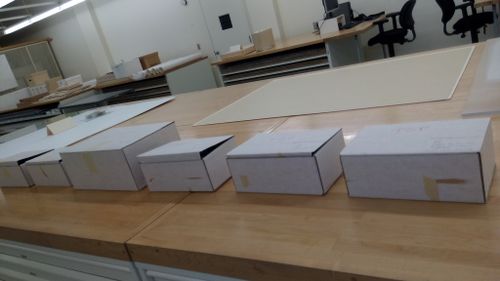
Unassembled pieces of model in 6 boxes, including notes on two folded sheets. One of the sheets contains notes and a sketch related to the scale of the model and the dimensions of human figures. The other sheet, dated 9 December 1974, contains a list of different types of furniture models with quantities and drawing references.
DR1995:0263:031
Description:
Unassembled pieces of model in 6 boxes, including notes on two folded sheets. One of the sheets contains notes and a sketch related to the scale of the model and the dimensions of human figures. The other sheet, dated 9 December 1974, contains a list of different types of furniture models with quantities and drawing references.
Personnes et institutions:
Date:
circa 1973-1975
circa 1973-1975
Titre:
McAppy: model for the Portable Enclosures Programme (PEP)
Actions:
DR1995:0263:031
Description:
Unassembled pieces of model in 6 boxes, including notes on two folded sheets. One of the sheets contains notes and a sketch related to the scale of the model and the dimensions of human figures. The other sheet, dated 9 December 1974, contains a list of different types of furniture models with quantities and drawing references.
Classification:
maquettes
maquettes
Date:
circa 1973-1975
circa 1973-1975
Personnes et institutions:
Classification:
maquettes
maquettes

Numéro de référence:
DR1995:0263:031-031
Description:
Unassembled pieces of model in 6 boxes, including notes on two folded sheets. One of the sheets contains notes and a sketch related to the scale of the model and the dimensions of human figures. The other sheet, dated 9 December 1974, contains a list of different types of furniture models with quantities and drawing references.
Personnes et institutions:
Date:
circa 1973-1975
circa 1973-1975
Titre:
McAppy: model for the Portable Enclosures Programme (PEP)
Actions:
DR1995:0263:031-031
Description:
Unassembled pieces of model in 6 boxes, including notes on two folded sheets. One of the sheets contains notes and a sketch related to the scale of the model and the dimensions of human figures. The other sheet, dated 9 December 1974, contains a list of different types of furniture models with quantities and drawing references.
Classification:
maquettes
maquettes
Date:
circa 1973-1975
circa 1973-1975
Personnes et institutions:
Classification:
photographies
Quantité:
4 negative(s)
photographies
Quantité:
4 negative(s)
Numéro de référence:
AP140.S2.SS1.D20.P3
Description:
views of one of the presentation drawings for part of an elevation for the steel mill cladding building, a small-scale presentation drawing for one complete elevation (also shown in the documents for the project), and two different views of a model which is not otherwise present in the project documents, for part of an elevation
Personnes et institutions:
Date:
1958 or after
1958 or after
Titre:
Presentation drawings and views of a model
Actions:
AP140.S2.SS1.D20.P3
Description:
views of one of the presentation drawings for part of an elevation for the steel mill cladding building, a small-scale presentation drawing for one complete elevation (also shown in the documents for the project), and two different views of a model which is not otherwise present in the project documents, for part of an elevation
Classification:
photographies
Quantité:
4 negative(s)
photographies
Quantité:
4 negative(s)
Date:
1958 or after
1958 or after
Personnes et institutions:
Classification:
maquettes
maquettes
Titre:
Carbon Tower section model
Carbon Tower section model
Numéro de référence:
AP174.S1.2001.D1.020
Description:
3D printed 1:50 scale metric model produced by 3D Systems in Valencia, California using selecting laser sintering (SLS). The model is in several pieces. Assembly instructions can be found in the "EXTREME TEXTILES ASSEMBLY GUIDES" folder contained within group AP174.S1.2001.D1.006 ("Working files and correspondence related to 3D printed models").
Personnes et institutions:
Date:
2005
2005
Titre:
Carbon Tower section model
Actions:
AP174.S1.2001.D1.020
Description:
3D printed 1:50 scale metric model produced by 3D Systems in Valencia, California using selecting laser sintering (SLS). The model is in several pieces. Assembly instructions can be found in the "EXTREME TEXTILES ASSEMBLY GUIDES" folder contained within group AP174.S1.2001.D1.006 ("Working files and correspondence related to 3D printed models").
Classification:
maquettes
maquettes
Date:
2005
2005
Personnes et institutions: