3666 Résultats
Classification:
archives
Niveau de description archivistique:
Fonds
archives
Niveau de description archivistique:
Fonds
Numéro de référence:
AP194
Résumé:
The Johan Bettum OCEAN North projects records, 1995-2000, consist of born-digital files and a physical drawing that document three projects by the OCEAN North collective: Synthetic Landscape (1995-2000), Jyväskylä Music and Arts Centre (competition, 1997), and Tölöö Football Stadium (competition, 1997). The archive also includes a small amount of additional born-digital reference materials on 11 projects from the collective, including the three projects mentioned above.
Personnes et institutions:
Date:
1995-2000
1995-2000
Titre:
Documents d’archives de Johan Bettum pour les projets de OCEAN North
Actions:
AP194
Résumé:
The Johan Bettum OCEAN North projects records, 1995-2000, consist of born-digital files and a physical drawing that document three projects by the OCEAN North collective: Synthetic Landscape (1995-2000), Jyväskylä Music and Arts Centre (competition, 1997), and Tölöö Football Stadium (competition, 1997). The archive also includes a small amount of additional born-digital reference materials on 11 projects from the collective, including the three projects mentioned above.
Classification:
archives
Niveau de description archivistique:
Fonds
archives
Niveau de description archivistique:
Fonds
Date:
1995-2000
1995-2000
Personnes et institutions:
Niveau de description archivistique:
Projet
Projet
Titre:
Riverplace, Columbus, Ohio
Riverplace, Columbus, Ohio
Numéro de référence:
AP143.S4.D81
Description:
File documents the unexectued project for Riverplace, Columbus, Ohio. Material in this file was produced in 1986 and 1989. File contains design development drawings, presentation drawings, presentation panels, reference drawings, and textual records. The design development drawings comprise sketches, site studies, and a series of Columbus, Ohio scaling analysis studies. Reference drawings include maps, aerial photos of Columbus, and a schematic plan by Cossutta & Associates, Architects, dated 1986. Textual records include filing index and directory, meeting minutes, transmittals and sketches.
Personnes et institutions:
Date:
1986, 1989
1986, 1989
Titre:
Riverplace, Columbus, Ohio
Actions:
AP143.S4.D81
Description:
File documents the unexectued project for Riverplace, Columbus, Ohio. Material in this file was produced in 1986 and 1989. File contains design development drawings, presentation drawings, presentation panels, reference drawings, and textual records. The design development drawings comprise sketches, site studies, and a series of Columbus, Ohio scaling analysis studies. Reference drawings include maps, aerial photos of Columbus, and a schematic plan by Cossutta & Associates, Architects, dated 1986. Textual records include filing index and directory, meeting minutes, transmittals and sketches.
Niveau de description archivistique:
File 81
File 81
Date:
1986, 1989
1986, 1989
Personnes et institutions:
Niveau de description archivistique:
Projet
Projet
Numéro de référence:
CI005.S1.1915.PR2
Description:
Oud designed a traditional West Netherlands farmhouse for his clients, Mr and Mrs Van Essen-Vinckers, in Blaricum, 1915. He revised his original design into the more modest Essen-Vinckers Villa. Oud was challenged to incorporate four bedrooms into the scaled down dwelling. The amended design featured a prominent chimney projecting from the living room through to the balcony and the upstairs bedroom (Taverne et al. 2001, 77-78). The project series includes plans as well as photographs of exterior views of the villa.
Personnes et institutions:
Date:
1915
1915
Titre:
Essen-Vinckers Villa, Blaricum, Netherlands (1915-1916)
Actions:
CI005.S1.1915.PR2
Description:
Oud designed a traditional West Netherlands farmhouse for his clients, Mr and Mrs Van Essen-Vinckers, in Blaricum, 1915. He revised his original design into the more modest Essen-Vinckers Villa. Oud was challenged to incorporate four bedrooms into the scaled down dwelling. The amended design featured a prominent chimney projecting from the living room through to the balcony and the upstairs bedroom (Taverne et al. 2001, 77-78). The project series includes plans as well as photographs of exterior views of the villa.
Niveau de description archivistique:
project
project
Date:
1915
1915
Personnes et institutions:
Classification:
dessins
Quantité:
10 drawing(s)
dessins
Quantité:
10 drawing(s)
Numéro de référence:
ARCH269760
Description:
Group consists of design exercises of different building typologies completed on pre-printed sheets. These include to-scale design development drawings of a two-family house, a bank, a mixed-use residential and commercial building, a country house, a schoolhouse, a youth hostel, and a cafe. Each exercise sheet inclues a space to complete floor plans, sections and elevations of the assigned building type.
Personnes et institutions:
Date:
1930-1931
1930-1931
Titre:
Design exercises of different building typologies completed on pre-printed sheets
Actions:
ARCH269760
Description:
Group consists of design exercises of different building typologies completed on pre-printed sheets. These include to-scale design development drawings of a two-family house, a bank, a mixed-use residential and commercial building, a country house, a schoolhouse, a youth hostel, and a cafe. Each exercise sheet inclues a space to complete floor plans, sections and elevations of the assigned building type.
Classification:
dessins
Quantité:
10 drawing(s)
dessins
Quantité:
10 drawing(s)
Date:
1930-1931
1930-1931
Personnes et institutions:
Classification:
dessins
dessins

Numéro de référence:
ARCH286690
Description:
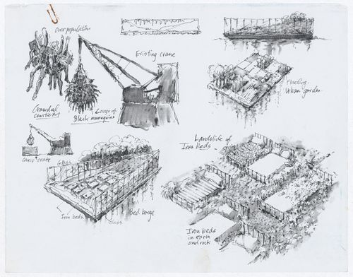
This item contains harmful materials including violent imagery. The drawing illustrates the discrete elements of an exhibition involving several large-scale installations. One of these installations shows a crane on which a net filled with mannequins is suspended; the mannequins are soaked in oil, in the words of the designers, to represent the impacts of oil spills on the global population. This image, however, suggests violence beyond environmental disasters.
ARCH286690
Description:
This item contains harmful materials including violent imagery. The drawing illustrates the discrete elements of an exhibition involving several large-scale installations. One of these installations shows a crane on which a net filled with mannequins is suspended; the mannequins are soaked in oil, in the words of the designers, to represent the impacts of oil spills on the global population. This image, however, suggests violence beyond environmental disasters.
Personnes et institutions:
Date:
circa 1999-2000
circa 1999-2000
Titre:
Drawings for two installations for the exhibition on James Wines at the Venice Biennale
Actions:
ARCH286690
Description:
This item contains harmful materials including violent imagery. The drawing illustrates the discrete elements of an exhibition involving several large-scale installations. One of these installations shows a crane on which a net filled with mannequins is suspended; the mannequins are soaked in oil, in the words of the designers, to represent the impacts of oil spills on the global population. This image, however, suggests violence beyond environmental disasters.
Classification:
dessins
dessins
Date:
circa 1999-2000
circa 1999-2000
Personnes et institutions:
Classification:
dessins
dessins
Numéro de référence:
ARCH286669
Description:
This item contains harmful materials including violent and racist imagery. The drawing illustrates the discrete elements of an exhibition involving several large-scale installations. One of these installations shows a crane on which a net filled with mannequins is suspended; the mannequins are painted black, in the words of the designers, to represent the impacts of oil spills on the global population. This image, however, suggests violence beyond environmental disasters.
Personnes et institutions:
Date:
circa 1999-2000
circa 1999-2000
Titre:
Drawing for the exhibition on James Wines at the Venice Biennale
Actions:
ARCH286669
Description:
This item contains harmful materials including violent and racist imagery. The drawing illustrates the discrete elements of an exhibition involving several large-scale installations. One of these installations shows a crane on which a net filled with mannequins is suspended; the mannequins are painted black, in the words of the designers, to represent the impacts of oil spills on the global population. This image, however, suggests violence beyond environmental disasters.
Classification:
dessins
dessins
Date:
circa 1999-2000
circa 1999-2000
Personnes et institutions:
Classification:
dessins
dessins
Actions:
Numéro de référence:
DR1989:0001
Description:
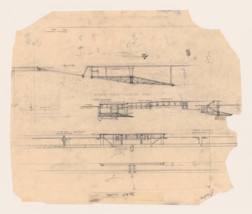
- In organization, presentation, scale and in most details this drawing corresponds to the lower half of the submitted competition panel (DR1987:0359) for which it is a preparatory drawing. Inscriptions at upper left and upper centre are instructions to the draughtsman (possibly himself) who would transfer these drawings to the panel. There are several small changes made in the submitted panel but the most noticeable is the section of the plane shed concourse.
DR1989:0001
Description:
- In organization, presentation, scale and in most details this drawing corresponds to the lower half of the submitted competition panel (DR1987:0359) for which it is a preparatory drawing. Inscriptions at upper left and upper centre are instructions to the draughtsman (possibly himself) who would transfer these drawings to the panel. There are several small changes made in the submitted panel but the most noticeable is the section of the plane shed concourse.
Personnes et institutions:
Sujet:
architecture
architecture
Date:
1929
1929
Titre:
Lehigh Airports Competition Entry: Elevation for the station and sections through the hangars and concourse
Actions:
DR1989:0001
Description:
- In organization, presentation, scale and in most details this drawing corresponds to the lower half of the submitted competition panel (DR1987:0359) for which it is a preparatory drawing. Inscriptions at upper left and upper centre are instructions to the draughtsman (possibly himself) who would transfer these drawings to the panel. There are several small changes made in the submitted panel but the most noticeable is the section of the plane shed concourse.
Classification:
dessins
dessins
Date:
1929
1929
Personnes et institutions:
Sujet:
architecture
architecture
Classification:
dessins
dessins
Actions:
Numéro de référence:
DR1987:0385
Description:
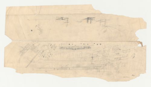
- This sheet contains a number of drawings, two of which are sketch elevations for airport buildings. While the upper complex has the scale and massing of many of Wright's Los Angeles Municipal Airport drawings, the lower drawing, with its tall observation tower standing out against a low station building, seems closer to his designs for Boeing Airport, Burbank, California (see DR1987:0391), or the Lehigh Airports Competition (see DR1987:0359).
DR1987:0385
Description:
- This sheet contains a number of drawings, two of which are sketch elevations for airport buildings. While the upper complex has the scale and massing of many of Wright's Los Angeles Municipal Airport drawings, the lower drawing, with its tall observation tower standing out against a low station building, seems closer to his designs for Boeing Airport, Burbank, California (see DR1987:0391), or the Lehigh Airports Competition (see DR1987:0359).
Personnes et institutions:
Sujet:
architecture
architecture
Date:
1929
1929
Titre:
Los Angeles Municipal Airport: Two sketch elevations with other unidentified sketches
Actions:
DR1987:0385
Description:
- This sheet contains a number of drawings, two of which are sketch elevations for airport buildings. While the upper complex has the scale and massing of many of Wright's Los Angeles Municipal Airport drawings, the lower drawing, with its tall observation tower standing out against a low station building, seems closer to his designs for Boeing Airport, Burbank, California (see DR1987:0391), or the Lehigh Airports Competition (see DR1987:0359).
Classification:
dessins
dessins
Date:
1929
1929
Personnes et institutions:
Sujet:
architecture
architecture
Classification:
archives
Niveau de description archivistique:
Fonds
archives
Niveau de description archivistique:
Fonds
Titre:
Gianni Pettena fonds
Gianni Pettena fonds
Numéro de référence:
AP207
Résumé:
The Gianni Pettena fonds documents Pettena’s work as an artist, architect, critic, and professor of history of contemporary architecture from the 1960s to the end of the 2010s. It includes one hundred artistic and architectural projects, material related to exhibitions he curated and designed, and his writings.
Personnes et institutions:
Date:
1960-2019
1960-2019
Titre:
Gianni Pettena fonds
Actions:
AP207
Résumé:
The Gianni Pettena fonds documents Pettena’s work as an artist, architect, critic, and professor of history of contemporary architecture from the 1960s to the end of the 2010s. It includes one hundred artistic and architectural projects, material related to exhibitions he curated and designed, and his writings.
Classification:
archives
Niveau de description archivistique:
Fonds
archives
Niveau de description archivistique:
Fonds
Date:
1960-2019
1960-2019
Personnes et institutions:
Classification:
dessins, documents textuels
dessins, documents textuels
Numéro de référence:
ARCH270995
Description:
Part 2, tome 1 : scales. It contains working drawings, project description, specifications and a budget.
ARCH270995
Description:
Part 2, tome 1 : scales. It contains working drawings, project description, specifications and a budget.
Personnes et institutions:
Date:
June 1998
June 1998
Titre:
Ring binder with textual records and plans from the project Planta de reciclaje de residuos urbanos de Valdemingómez, Madrid, Spain
Actions:
ARCH270995
Description:
Part 2, tome 1 : scales. It contains working drawings, project description, specifications and a budget.
Ring binder with textual records and plans from the project Planta de reciclaje de residuos urbanos de Valdemingómez, Madrid, Spain
Actions:
ARCH270995
Description:
Part 2, tome 1 : scales. It contains working drawings, project description, specifications and a budget.
Classification:
dessins, documents textuels
dessins, documents textuels
Date:
June 1998
June 1998
Personnes et institutions: