


12885 Résultats
Niveau de description archivistique:
Sous-série
Sous-série
Numéro de référence:
AP129.S1.D7.P1
Description:
Cette série de projet documente le projet de Ouellet, Reeves, Alain, architectes pour la Garage Louis Colin de l'Université de Montréal, à Montréal, Québec. Le projet reporte la Médaille Massey en architecture en 1970 et le Concours pour ouvrage en béton, attestation de modèles canadiens remarquables en 1971. La série de projet est constitué de documents photographiques et textuels, ainsi que de dessins.
AP129.S1.D7.P1
Description:
Cette série de projet documente le projet de Ouellet, Reeves, Alain, architectes pour la Garage Louis Colin de l'Université de Montréal, à Montréal, Québec. Le projet reporte la Médaille Massey en architecture en 1970 et le Concours pour ouvrage en béton, attestation de modèles canadiens remarquables en 1971. La série de projet est constitué de documents photographiques et textuels, ainsi que de dessins.
Personnes et institutions:
Date:
1944-1998
1944-1998
Titre:
Garage Louis Colin, Université de Montréal, Montréal, Québec
Actions:
AP129.S1.D7.P1
Description:
Cette série de projet documente le projet de Ouellet, Reeves, Alain, architectes pour la Garage Louis Colin de l'Université de Montréal, à Montréal, Québec. Le projet reporte la Médaille Massey en architecture en 1970 et le Concours pour ouvrage en béton, attestation de modèles canadiens remarquables en 1971. La série de projet est constitué de documents photographiques et textuels, ainsi que de dessins.
Garage Louis Colin, Université de Montréal, Montréal, Québec
Actions:
AP129.S1.D7.P1
Description:
Cette série de projet documente le projet de Ouellet, Reeves, Alain, architectes pour la Garage Louis Colin de l'Université de Montréal, à Montréal, Québec. Le projet reporte la Médaille Massey en architecture en 1970 et le Concours pour ouvrage en béton, attestation de modèles canadiens remarquables en 1971. La série de projet est constitué de documents photographiques et textuels, ainsi que de dessins.
Niveau de description archivistique:
Projet 1
Projet 1
Date:
1944-1998
1944-1998
Personnes et institutions:
Classification:
documents textuels
documents textuels
Numéro de référence:
ARCH257321
Description:
mixed reports: Transit Station and Large Public assembly Facilities, Office Buildings, Science, Technology and Computer Centres, Museum Packet, Mid East Projects, Hotel List, Law Courts, Office buildings and Data Centres, Project Descriptions R-Z, Projects list, Notes AEA Projects, miscellaneous Photographs: miscellaneous unidentified, Yordale Subway Station, The World Bank, Western Washington, Woodside Residence, Robson Sqaure, Witting Place, U.C Irvine, USCD, Vancouver Art Gallery, Wall Street, Westin Bayshore, Wilshire Art Complex, Village Lake Louise, Taos Resort Study Model, SunLife Building, U.B.C Facility Club, University of Victoria, Tokyo international Trade Fair Pavillon, Teck Mining, Sunkin House, Saudi Embassy, Sawaber Housing, Spadina Quay, Songhees Seniors Tower, Shangai Culture, Saskatoon Hospital
ARCH257321
Description:
mixed reports: Transit Station and Large Public assembly Facilities, Office Buildings, Science, Technology and Computer Centres, Museum Packet, Mid East Projects, Hotel List, Law Courts, Office buildings and Data Centres, Project Descriptions R-Z, Projects list, Notes AEA Projects, miscellaneous Photographs: miscellaneous unidentified, Yordale Subway Station, The World Bank, Western Washington, Woodside Residence, Robson Sqaure, Witting Place, U.C Irvine, USCD, Vancouver Art Gallery, Wall Street, Westin Bayshore, Wilshire Art Complex, Village Lake Louise, Taos Resort Study Model, SunLife Building, U.B.C Facility Club, University of Victoria, Tokyo international Trade Fair Pavillon, Teck Mining, Sunkin House, Saudi Embassy, Sawaber Housing, Spadina Quay, Songhees Seniors Tower, Shangai Culture, Saskatoon Hospital
Personnes et institutions:
Titre:
Reports, projects descriptions and projects photographs for promotion
Actions:
ARCH257321
Description:
mixed reports: Transit Station and Large Public assembly Facilities, Office Buildings, Science, Technology and Computer Centres, Museum Packet, Mid East Projects, Hotel List, Law Courts, Office buildings and Data Centres, Project Descriptions R-Z, Projects list, Notes AEA Projects, miscellaneous Photographs: miscellaneous unidentified, Yordale Subway Station, The World Bank, Western Washington, Woodside Residence, Robson Sqaure, Witting Place, U.C Irvine, USCD, Vancouver Art Gallery, Wall Street, Westin Bayshore, Wilshire Art Complex, Village Lake Louise, Taos Resort Study Model, SunLife Building, U.B.C Facility Club, University of Victoria, Tokyo international Trade Fair Pavillon, Teck Mining, Sunkin House, Saudi Embassy, Sawaber Housing, Spadina Quay, Songhees Seniors Tower, Shangai Culture, Saskatoon Hospital
Reports, projects descriptions and projects photographs for promotion
Actions:
ARCH257321
Description:
mixed reports: Transit Station and Large Public assembly Facilities, Office Buildings, Science, Technology and Computer Centres, Museum Packet, Mid East Projects, Hotel List, Law Courts, Office buildings and Data Centres, Project Descriptions R-Z, Projects list, Notes AEA Projects, miscellaneous Photographs: miscellaneous unidentified, Yordale Subway Station, The World Bank, Western Washington, Woodside Residence, Robson Sqaure, Witting Place, U.C Irvine, USCD, Vancouver Art Gallery, Wall Street, Westin Bayshore, Wilshire Art Complex, Village Lake Louise, Taos Resort Study Model, SunLife Building, U.B.C Facility Club, University of Victoria, Tokyo international Trade Fair Pavillon, Teck Mining, Sunkin House, Saudi Embassy, Sawaber Housing, Spadina Quay, Songhees Seniors Tower, Shangai Culture, Saskatoon Hospital
Classification:
documents textuels
documents textuels
Personnes et institutions:
Classification:
dessins
dessins
Numéro de référence:
AP154.S1.1973.PR01.SS2.035
Description:
Thirty-two drawings numbered 1, BD1, C114, LP205, S11-S12, and SK1 through SK205 with significant gaps. Drawings include section thru elevator core, section thru stair, spandrel heights, street elevations, section at lobby steps, partial plans, expansion joints (record of observation), special mullions at 1st floor (General Bronze Corporation), column schedule center core, loading platform and bumper, building model, lighting plan, fire exit signs, building elevations along north sides of E. 51st and 54th Streets (George A. Fuller Company), Four Seasons Restaurant--chain barrier details, ceiling revision (9th fl.), construction plan, rev'd bumper guard, front stair const., architectural symbols and abbreviations, truck entrance and loading dock, and window unit.
AP154.S1.1973.PR01.SS2.035
Description:
Thirty-two drawings numbered 1, BD1, C114, LP205, S11-S12, and SK1 through SK205 with significant gaps. Drawings include section thru elevator core, section thru stair, spandrel heights, street elevations, section at lobby steps, partial plans, expansion joints (record of observation), special mullions at 1st floor (General Bronze Corporation), column schedule center core, loading platform and bumper, building model, lighting plan, fire exit signs, building elevations along north sides of E. 51st and 54th Streets (George A. Fuller Company), Four Seasons Restaurant--chain barrier details, ceiling revision (9th fl.), construction plan, rev'd bumper guard, front stair const., architectural symbols and abbreviations, truck entrance and loading dock, and window unit.
Personnes et institutions:
Date:
1955-1963
1955-1963
Titre:
Copies of drawings for the Seagram Building, 375 Park Avenue, New York, N.Y.
Actions:
AP154.S1.1973.PR01.SS2.035
Description:
Thirty-two drawings numbered 1, BD1, C114, LP205, S11-S12, and SK1 through SK205 with significant gaps. Drawings include section thru elevator core, section thru stair, spandrel heights, street elevations, section at lobby steps, partial plans, expansion joints (record of observation), special mullions at 1st floor (General Bronze Corporation), column schedule center core, loading platform and bumper, building model, lighting plan, fire exit signs, building elevations along north sides of E. 51st and 54th Streets (George A. Fuller Company), Four Seasons Restaurant--chain barrier details, ceiling revision (9th fl.), construction plan, rev'd bumper guard, front stair const., architectural symbols and abbreviations, truck entrance and loading dock, and window unit.
Copies of drawings for the Seagram Building, 375 Park Avenue, New York, N.Y.
Actions:
AP154.S1.1973.PR01.SS2.035
Description:
Thirty-two drawings numbered 1, BD1, C114, LP205, S11-S12, and SK1 through SK205 with significant gaps. Drawings include section thru elevator core, section thru stair, spandrel heights, street elevations, section at lobby steps, partial plans, expansion joints (record of observation), special mullions at 1st floor (General Bronze Corporation), column schedule center core, loading platform and bumper, building model, lighting plan, fire exit signs, building elevations along north sides of E. 51st and 54th Streets (George A. Fuller Company), Four Seasons Restaurant--chain barrier details, ceiling revision (9th fl.), construction plan, rev'd bumper guard, front stair const., architectural symbols and abbreviations, truck entrance and loading dock, and window unit.
Classification:
dessins
dessins
Date:
1955-1963
1955-1963
Personnes et institutions:
Niveau de description archivistique:
Série(s)
Série(s)
Numéro de référence:
AP184.S1
Description:
Series 1, Three Dimensional Trading Floor, 1990 - 2009, relates to Asymptote Architecture’s design of a virtualized NYSE Trading Floor that visualized real-time numerical and statistical data. This series includes textual, born-digital, and audiovisual components, as well as digital artefacts, and chiefly dates from 1997 to 2002. The intent of the New York Stock Exchange Three Dimensional Trading Floor (3DTF) was to detect suspicious trading activity, track the impact of global news events on the market and potentially predict a crash before it happened. In order to achieve this technically, Asymptote worked with Silicon Graphics Incorporated (SGI) RealityEngine hardware which had been built specifically for these visualization-intensive applications. They also worked with Softimage and Alias software for modeling, rendering and animating, and VRML (Virtual Reality Markup Language) and Macromedia Flash in order to integrate real-time data into a navigable three-dimensional environment. The main elements of the virtual environment include posts, containers, and back wall. The two container types, Index Container (IC) and Group Container (GC), allow for visualization and comparison of stock histories and behaviors. The posts display stock information, corresponding heat maps on floors, and alerts. The back wall integrates live news broadcasts. Materials in this series are largely digital and primarily include still raster images and video demonstrating 3DTF functionality. There is also a small body of CAD material in Maya, Alias, Microstation, and Form-Z formats. Other digital materials include Virtual Reality Markup Language (VRML) files, HTML files, Silicon Graphics Images databases, research material, press kits, presentations, and handout files. The textual records are largely materials that were handed out at presentation meetings for each phase of the project. These typically illustrate major virtual components of 3DTF, like the heat maps and posts, and overlap significantly with the related digital files. There is also one VHS tape which compiles nearly twenty minutes of animated renderings. Finally, this series includes 43 CDs. The CDs were processed and are included as part of the digital records; the CDs themselves were kept in instances where they may have artefactual value, especially if they were visually interesting or informationally important.
AP184.S1
Description:
Series 1, Three Dimensional Trading Floor, 1990 - 2009, relates to Asymptote Architecture’s design of a virtualized NYSE Trading Floor that visualized real-time numerical and statistical data. This series includes textual, born-digital, and audiovisual components, as well as digital artefacts, and chiefly dates from 1997 to 2002. The intent of the New York Stock Exchange Three Dimensional Trading Floor (3DTF) was to detect suspicious trading activity, track the impact of global news events on the market and potentially predict a crash before it happened. In order to achieve this technically, Asymptote worked with Silicon Graphics Incorporated (SGI) RealityEngine hardware which had been built specifically for these visualization-intensive applications. They also worked with Softimage and Alias software for modeling, rendering and animating, and VRML (Virtual Reality Markup Language) and Macromedia Flash in order to integrate real-time data into a navigable three-dimensional environment. The main elements of the virtual environment include posts, containers, and back wall. The two container types, Index Container (IC) and Group Container (GC), allow for visualization and comparison of stock histories and behaviors. The posts display stock information, corresponding heat maps on floors, and alerts. The back wall integrates live news broadcasts. Materials in this series are largely digital and primarily include still raster images and video demonstrating 3DTF functionality. There is also a small body of CAD material in Maya, Alias, Microstation, and Form-Z formats. Other digital materials include Virtual Reality Markup Language (VRML) files, HTML files, Silicon Graphics Images databases, research material, press kits, presentations, and handout files. The textual records are largely materials that were handed out at presentation meetings for each phase of the project. These typically illustrate major virtual components of 3DTF, like the heat maps and posts, and overlap significantly with the related digital files. There is also one VHS tape which compiles nearly twenty minutes of animated renderings. Finally, this series includes 43 CDs. The CDs were processed and are included as part of the digital records; the CDs themselves were kept in instances where they may have artefactual value, especially if they were visually interesting or informationally important.
Personnes et institutions:
Date:
1990-2009
1990-2009
Titre:
Three Dimensional Trading Floor
Actions:
AP184.S1
Description:
Series 1, Three Dimensional Trading Floor, 1990 - 2009, relates to Asymptote Architecture’s design of a virtualized NYSE Trading Floor that visualized real-time numerical and statistical data. This series includes textual, born-digital, and audiovisual components, as well as digital artefacts, and chiefly dates from 1997 to 2002. The intent of the New York Stock Exchange Three Dimensional Trading Floor (3DTF) was to detect suspicious trading activity, track the impact of global news events on the market and potentially predict a crash before it happened. In order to achieve this technically, Asymptote worked with Silicon Graphics Incorporated (SGI) RealityEngine hardware which had been built specifically for these visualization-intensive applications. They also worked with Softimage and Alias software for modeling, rendering and animating, and VRML (Virtual Reality Markup Language) and Macromedia Flash in order to integrate real-time data into a navigable three-dimensional environment. The main elements of the virtual environment include posts, containers, and back wall. The two container types, Index Container (IC) and Group Container (GC), allow for visualization and comparison of stock histories and behaviors. The posts display stock information, corresponding heat maps on floors, and alerts. The back wall integrates live news broadcasts. Materials in this series are largely digital and primarily include still raster images and video demonstrating 3DTF functionality. There is also a small body of CAD material in Maya, Alias, Microstation, and Form-Z formats. Other digital materials include Virtual Reality Markup Language (VRML) files, HTML files, Silicon Graphics Images databases, research material, press kits, presentations, and handout files. The textual records are largely materials that were handed out at presentation meetings for each phase of the project. These typically illustrate major virtual components of 3DTF, like the heat maps and posts, and overlap significantly with the related digital files. There is also one VHS tape which compiles nearly twenty minutes of animated renderings. Finally, this series includes 43 CDs. The CDs were processed and are included as part of the digital records; the CDs themselves were kept in instances where they may have artefactual value, especially if they were visually interesting or informationally important.
Three Dimensional Trading Floor
Actions:
AP184.S1
Description:
Series 1, Three Dimensional Trading Floor, 1990 - 2009, relates to Asymptote Architecture’s design of a virtualized NYSE Trading Floor that visualized real-time numerical and statistical data. This series includes textual, born-digital, and audiovisual components, as well as digital artefacts, and chiefly dates from 1997 to 2002. The intent of the New York Stock Exchange Three Dimensional Trading Floor (3DTF) was to detect suspicious trading activity, track the impact of global news events on the market and potentially predict a crash before it happened. In order to achieve this technically, Asymptote worked with Silicon Graphics Incorporated (SGI) RealityEngine hardware which had been built specifically for these visualization-intensive applications. They also worked with Softimage and Alias software for modeling, rendering and animating, and VRML (Virtual Reality Markup Language) and Macromedia Flash in order to integrate real-time data into a navigable three-dimensional environment. The main elements of the virtual environment include posts, containers, and back wall. The two container types, Index Container (IC) and Group Container (GC), allow for visualization and comparison of stock histories and behaviors. The posts display stock information, corresponding heat maps on floors, and alerts. The back wall integrates live news broadcasts. Materials in this series are largely digital and primarily include still raster images and video demonstrating 3DTF functionality. There is also a small body of CAD material in Maya, Alias, Microstation, and Form-Z formats. Other digital materials include Virtual Reality Markup Language (VRML) files, HTML files, Silicon Graphics Images databases, research material, press kits, presentations, and handout files. The textual records are largely materials that were handed out at presentation meetings for each phase of the project. These typically illustrate major virtual components of 3DTF, like the heat maps and posts, and overlap significantly with the related digital files. There is also one VHS tape which compiles nearly twenty minutes of animated renderings. Finally, this series includes 43 CDs. The CDs were processed and are included as part of the digital records; the CDs themselves were kept in instances where they may have artefactual value, especially if they were visually interesting or informationally important.
Niveau de description archivistique:
Series
Series
Date:
1990-2009
1990-2009
Personnes et institutions:
Classification:
photographies
photographies
Numéro de référence:
ARCH269364
Description:
Contains photographic materials on projects by Abalos & Herreros: - Vivienda experimental (12 slides: plans); - Proyecto de subestacion y edificio de oficinas para el puerto de Carboneras, Almeria (44 slides: interior/exterior views and construction); - Entrada desde la puerta del cambron, Bup 12 unidades Santiago de la Fuente, Toledo (51 slides: interior/exterior views and plans); - Linea de mobiliario Euterpe (19 slides: views of seats and tables); - Auditorio al aire libre en la casa de campo (66 slides: plans, interior/exterior views, construction); - Centro Cultural, Cobeña, Madrid, AP164.S1.1986.D4 (30 slides, 1 negative : views of model, interior views and 1 plan); - Polideportivo y piscina cubierta de Vallecas, AP164.S1.1986.D1 (30 slides, 1 negative: interior/exterior views, construction and plans).
ARCH269364
Description:
Contains photographic materials on projects by Abalos & Herreros: - Vivienda experimental (12 slides: plans); - Proyecto de subestacion y edificio de oficinas para el puerto de Carboneras, Almeria (44 slides: interior/exterior views and construction); - Entrada desde la puerta del cambron, Bup 12 unidades Santiago de la Fuente, Toledo (51 slides: interior/exterior views and plans); - Linea de mobiliario Euterpe (19 slides: views of seats and tables); - Auditorio al aire libre en la casa de campo (66 slides: plans, interior/exterior views, construction); - Centro Cultural, Cobeña, Madrid, AP164.S1.1986.D4 (30 slides, 1 negative : views of model, interior views and 1 plan); - Polideportivo y piscina cubierta de Vallecas, AP164.S1.1986.D1 (30 slides, 1 negative: interior/exterior views, construction and plans).
Personnes et institutions:
Date:
ca. 1988
ca. 1988
Titre:
Ring binder with photographic materials related to seven projects by Abalos & Herreros
Actions:
ARCH269364
Description:
Contains photographic materials on projects by Abalos & Herreros: - Vivienda experimental (12 slides: plans); - Proyecto de subestacion y edificio de oficinas para el puerto de Carboneras, Almeria (44 slides: interior/exterior views and construction); - Entrada desde la puerta del cambron, Bup 12 unidades Santiago de la Fuente, Toledo (51 slides: interior/exterior views and plans); - Linea de mobiliario Euterpe (19 slides: views of seats and tables); - Auditorio al aire libre en la casa de campo (66 slides: plans, interior/exterior views, construction); - Centro Cultural, Cobeña, Madrid, AP164.S1.1986.D4 (30 slides, 1 negative : views of model, interior views and 1 plan); - Polideportivo y piscina cubierta de Vallecas, AP164.S1.1986.D1 (30 slides, 1 negative: interior/exterior views, construction and plans).
Ring binder with photographic materials related to seven projects by Abalos & Herreros
Actions:
ARCH269364
Description:
Contains photographic materials on projects by Abalos & Herreros: - Vivienda experimental (12 slides: plans); - Proyecto de subestacion y edificio de oficinas para el puerto de Carboneras, Almeria (44 slides: interior/exterior views and construction); - Entrada desde la puerta del cambron, Bup 12 unidades Santiago de la Fuente, Toledo (51 slides: interior/exterior views and plans); - Linea de mobiliario Euterpe (19 slides: views of seats and tables); - Auditorio al aire libre en la casa de campo (66 slides: plans, interior/exterior views, construction); - Centro Cultural, Cobeña, Madrid, AP164.S1.1986.D4 (30 slides, 1 negative : views of model, interior views and 1 plan); - Polideportivo y piscina cubierta de Vallecas, AP164.S1.1986.D1 (30 slides, 1 negative: interior/exterior views, construction and plans).
Classification:
photographies
photographies
Date:
ca. 1988
ca. 1988
Personnes et institutions:
Niveau de description archivistique:
Série(s)
Série(s)
Titre:
Architectural projects
Architectural projects
Numéro de référence:
AP178.S1
Description:
Series AP178.S1 is the largest series of the Álvaro Siza fonds and documents over 200 of Siza’s built and unbuilt architectural projects. The series is divided into project series which are arranged chronologically by project year. Presently, materials in this series range from 1958-2012. The CCA will also receive materials documenting Siza’s more recent work in future additions. Documenting the projects are conceptual, design, presentation, and working drawings, as well as photographic materials, textual documentation, and models. Although the drawings for each project have been identified, Siza often sketches or doodles on textual documentation, such as minutes of meetings or notes. When possible, folders that include textual documents with sketches or doodles have been identified. Amounts and types of materials vary from project to project. Project documentation is usually in Portuguese, with some exceptions including French, English, German, and Dutch. Most project series include sketches, studies, and working drawings. Other drawings included are site plans, floor plans, topographic surveys, elevations, sections, as well as technical and mechanical details. Also documenting the projects are photographic materials and textual documentation, such as correspondence, building programs, contracts, notes, and other working details. Photographic materials found within this archive are slides, negatives, photomontages and photographs of project sites and models.The photomontages were often used to study the function of the project site. To fully understand Siza’s methodology, sketchbooks (Series AP178.S2) should be viewed alongside the project drawings, when possible. Each project series description highlights sketchbooks in series AP178.S2 which contain related sketches. It is important to note that not all projects are represented in the sketchbooks in Series AP178.S2. Moreover, project series descriptions only list related sketchbooks when sketches have been positively identified as related to the corresponding project. The Siza fonds will be processed in four phases. The materials processed in the first, second, and third phases are architectural projects from the 1950’s, 1960’s, and 1970’s; urban planning projects; Reconstrução do Chiado; Berlin projects submitted to the IBA competition; cultural institutions; individual houses; and the Plano de urbanização Deelgebied 5 Schilderswijk-West in The Hague. Among The Hague and the Berlin projects are the Punt en Komma social housing, Bonjour Tristesse, and the Residential settlement in Schilderswijk. This series is better understood in the context of how the records for architectural projects were arranged by Siza’s office. Earlier projects were initially numbered by Siza’s office and then received new project numbers by the office archivist, who joined the office in the 1990s. Project files have been kept in the order in which they were received by the CCA, which is how they were arranged by the office archivist. The project numbers and dates assigned by Siza’s office archivist are included in the descriptions for each project and form the basis for the arrangement of this series. The office archivist numbered projects consecutively by decade, for instance, 58/80 was the 58th project during the 1980s. Numbers which were included in square brackets, ex. [14]/75, show that the project was not a ‘full’ project and contains a small amount of documentation. When projects are followed by a letter (A, B, C) this signifies a project is connected to the first. When the project number is followed by a number (1, 2, 3) this signifies a separate building within a larger project. For the purposes of arrangement, project numbers that were assigned a letter or number are arranged as sub-series of the related project series. Exceptions to this numbering convention are projects 23/60, 25/60, 28/60, 33/60, 34/60 and 35/60. These projects were not in the office’s original project list and were not officially considered projects. The office archivist assembled documentation related to these projects and assigned them numbers. In the early 2000s a large number of photographic materials were gathered together by the office archivist from various correspondence files for a digitization project initiated by the office. These materials remained housed together as a photograph collection in the office. Not all of these materials were digitized by the office. Those that were digitized were assigned numbers which have been identified in the file descriptions. It is important to note that several photographic materials were left with the textual documentation or drawings. When this is the case they are identified in the file description. There are also several panoramic photomontages which were created by either gluing or taping several photographs together to make panoramas of project sites.
AP178.S1
Description:
Series AP178.S1 is the largest series of the Álvaro Siza fonds and documents over 200 of Siza’s built and unbuilt architectural projects. The series is divided into project series which are arranged chronologically by project year. Presently, materials in this series range from 1958-2012. The CCA will also receive materials documenting Siza’s more recent work in future additions. Documenting the projects are conceptual, design, presentation, and working drawings, as well as photographic materials, textual documentation, and models. Although the drawings for each project have been identified, Siza often sketches or doodles on textual documentation, such as minutes of meetings or notes. When possible, folders that include textual documents with sketches or doodles have been identified. Amounts and types of materials vary from project to project. Project documentation is usually in Portuguese, with some exceptions including French, English, German, and Dutch. Most project series include sketches, studies, and working drawings. Other drawings included are site plans, floor plans, topographic surveys, elevations, sections, as well as technical and mechanical details. Also documenting the projects are photographic materials and textual documentation, such as correspondence, building programs, contracts, notes, and other working details. Photographic materials found within this archive are slides, negatives, photomontages and photographs of project sites and models.The photomontages were often used to study the function of the project site. To fully understand Siza’s methodology, sketchbooks (Series AP178.S2) should be viewed alongside the project drawings, when possible. Each project series description highlights sketchbooks in series AP178.S2 which contain related sketches. It is important to note that not all projects are represented in the sketchbooks in Series AP178.S2. Moreover, project series descriptions only list related sketchbooks when sketches have been positively identified as related to the corresponding project. The Siza fonds will be processed in four phases. The materials processed in the first, second, and third phases are architectural projects from the 1950’s, 1960’s, and 1970’s; urban planning projects; Reconstrução do Chiado; Berlin projects submitted to the IBA competition; cultural institutions; individual houses; and the Plano de urbanização Deelgebied 5 Schilderswijk-West in The Hague. Among The Hague and the Berlin projects are the Punt en Komma social housing, Bonjour Tristesse, and the Residential settlement in Schilderswijk. This series is better understood in the context of how the records for architectural projects were arranged by Siza’s office. Earlier projects were initially numbered by Siza’s office and then received new project numbers by the office archivist, who joined the office in the 1990s. Project files have been kept in the order in which they were received by the CCA, which is how they were arranged by the office archivist. The project numbers and dates assigned by Siza’s office archivist are included in the descriptions for each project and form the basis for the arrangement of this series. The office archivist numbered projects consecutively by decade, for instance, 58/80 was the 58th project during the 1980s. Numbers which were included in square brackets, ex. [14]/75, show that the project was not a ‘full’ project and contains a small amount of documentation. When projects are followed by a letter (A, B, C) this signifies a project is connected to the first. When the project number is followed by a number (1, 2, 3) this signifies a separate building within a larger project. For the purposes of arrangement, project numbers that were assigned a letter or number are arranged as sub-series of the related project series. Exceptions to this numbering convention are projects 23/60, 25/60, 28/60, 33/60, 34/60 and 35/60. These projects were not in the office’s original project list and were not officially considered projects. The office archivist assembled documentation related to these projects and assigned them numbers. In the early 2000s a large number of photographic materials were gathered together by the office archivist from various correspondence files for a digitization project initiated by the office. These materials remained housed together as a photograph collection in the office. Not all of these materials were digitized by the office. Those that were digitized were assigned numbers which have been identified in the file descriptions. It is important to note that several photographic materials were left with the textual documentation or drawings. When this is the case they are identified in the file description. There are also several panoramic photomontages which were created by either gluing or taping several photographs together to make panoramas of project sites.
Personnes et institutions:
Date:
1948-2012
1948-2012
Titre:
Architectural projects
Actions:
AP178.S1
Description:
Series AP178.S1 is the largest series of the Álvaro Siza fonds and documents over 200 of Siza’s built and unbuilt architectural projects. The series is divided into project series which are arranged chronologically by project year. Presently, materials in this series range from 1958-2012. The CCA will also receive materials documenting Siza’s more recent work in future additions. Documenting the projects are conceptual, design, presentation, and working drawings, as well as photographic materials, textual documentation, and models. Although the drawings for each project have been identified, Siza often sketches or doodles on textual documentation, such as minutes of meetings or notes. When possible, folders that include textual documents with sketches or doodles have been identified. Amounts and types of materials vary from project to project. Project documentation is usually in Portuguese, with some exceptions including French, English, German, and Dutch. Most project series include sketches, studies, and working drawings. Other drawings included are site plans, floor plans, topographic surveys, elevations, sections, as well as technical and mechanical details. Also documenting the projects are photographic materials and textual documentation, such as correspondence, building programs, contracts, notes, and other working details. Photographic materials found within this archive are slides, negatives, photomontages and photographs of project sites and models.The photomontages were often used to study the function of the project site. To fully understand Siza’s methodology, sketchbooks (Series AP178.S2) should be viewed alongside the project drawings, when possible. Each project series description highlights sketchbooks in series AP178.S2 which contain related sketches. It is important to note that not all projects are represented in the sketchbooks in Series AP178.S2. Moreover, project series descriptions only list related sketchbooks when sketches have been positively identified as related to the corresponding project. The Siza fonds will be processed in four phases. The materials processed in the first, second, and third phases are architectural projects from the 1950’s, 1960’s, and 1970’s; urban planning projects; Reconstrução do Chiado; Berlin projects submitted to the IBA competition; cultural institutions; individual houses; and the Plano de urbanização Deelgebied 5 Schilderswijk-West in The Hague. Among The Hague and the Berlin projects are the Punt en Komma social housing, Bonjour Tristesse, and the Residential settlement in Schilderswijk. This series is better understood in the context of how the records for architectural projects were arranged by Siza’s office. Earlier projects were initially numbered by Siza’s office and then received new project numbers by the office archivist, who joined the office in the 1990s. Project files have been kept in the order in which they were received by the CCA, which is how they were arranged by the office archivist. The project numbers and dates assigned by Siza’s office archivist are included in the descriptions for each project and form the basis for the arrangement of this series. The office archivist numbered projects consecutively by decade, for instance, 58/80 was the 58th project during the 1980s. Numbers which were included in square brackets, ex. [14]/75, show that the project was not a ‘full’ project and contains a small amount of documentation. When projects are followed by a letter (A, B, C) this signifies a project is connected to the first. When the project number is followed by a number (1, 2, 3) this signifies a separate building within a larger project. For the purposes of arrangement, project numbers that were assigned a letter or number are arranged as sub-series of the related project series. Exceptions to this numbering convention are projects 23/60, 25/60, 28/60, 33/60, 34/60 and 35/60. These projects were not in the office’s original project list and were not officially considered projects. The office archivist assembled documentation related to these projects and assigned them numbers. In the early 2000s a large number of photographic materials were gathered together by the office archivist from various correspondence files for a digitization project initiated by the office. These materials remained housed together as a photograph collection in the office. Not all of these materials were digitized by the office. Those that were digitized were assigned numbers which have been identified in the file descriptions. It is important to note that several photographic materials were left with the textual documentation or drawings. When this is the case they are identified in the file description. There are also several panoramic photomontages which were created by either gluing or taping several photographs together to make panoramas of project sites.
Architectural projects
Actions:
AP178.S1
Description:
Series AP178.S1 is the largest series of the Álvaro Siza fonds and documents over 200 of Siza’s built and unbuilt architectural projects. The series is divided into project series which are arranged chronologically by project year. Presently, materials in this series range from 1958-2012. The CCA will also receive materials documenting Siza’s more recent work in future additions. Documenting the projects are conceptual, design, presentation, and working drawings, as well as photographic materials, textual documentation, and models. Although the drawings for each project have been identified, Siza often sketches or doodles on textual documentation, such as minutes of meetings or notes. When possible, folders that include textual documents with sketches or doodles have been identified. Amounts and types of materials vary from project to project. Project documentation is usually in Portuguese, with some exceptions including French, English, German, and Dutch. Most project series include sketches, studies, and working drawings. Other drawings included are site plans, floor plans, topographic surveys, elevations, sections, as well as technical and mechanical details. Also documenting the projects are photographic materials and textual documentation, such as correspondence, building programs, contracts, notes, and other working details. Photographic materials found within this archive are slides, negatives, photomontages and photographs of project sites and models.The photomontages were often used to study the function of the project site. To fully understand Siza’s methodology, sketchbooks (Series AP178.S2) should be viewed alongside the project drawings, when possible. Each project series description highlights sketchbooks in series AP178.S2 which contain related sketches. It is important to note that not all projects are represented in the sketchbooks in Series AP178.S2. Moreover, project series descriptions only list related sketchbooks when sketches have been positively identified as related to the corresponding project. The Siza fonds will be processed in four phases. The materials processed in the first, second, and third phases are architectural projects from the 1950’s, 1960’s, and 1970’s; urban planning projects; Reconstrução do Chiado; Berlin projects submitted to the IBA competition; cultural institutions; individual houses; and the Plano de urbanização Deelgebied 5 Schilderswijk-West in The Hague. Among The Hague and the Berlin projects are the Punt en Komma social housing, Bonjour Tristesse, and the Residential settlement in Schilderswijk. This series is better understood in the context of how the records for architectural projects were arranged by Siza’s office. Earlier projects were initially numbered by Siza’s office and then received new project numbers by the office archivist, who joined the office in the 1990s. Project files have been kept in the order in which they were received by the CCA, which is how they were arranged by the office archivist. The project numbers and dates assigned by Siza’s office archivist are included in the descriptions for each project and form the basis for the arrangement of this series. The office archivist numbered projects consecutively by decade, for instance, 58/80 was the 58th project during the 1980s. Numbers which were included in square brackets, ex. [14]/75, show that the project was not a ‘full’ project and contains a small amount of documentation. When projects are followed by a letter (A, B, C) this signifies a project is connected to the first. When the project number is followed by a number (1, 2, 3) this signifies a separate building within a larger project. For the purposes of arrangement, project numbers that were assigned a letter or number are arranged as sub-series of the related project series. Exceptions to this numbering convention are projects 23/60, 25/60, 28/60, 33/60, 34/60 and 35/60. These projects were not in the office’s original project list and were not officially considered projects. The office archivist assembled documentation related to these projects and assigned them numbers. In the early 2000s a large number of photographic materials were gathered together by the office archivist from various correspondence files for a digitization project initiated by the office. These materials remained housed together as a photograph collection in the office. Not all of these materials were digitized by the office. Those that were digitized were assigned numbers which have been identified in the file descriptions. It is important to note that several photographic materials were left with the textual documentation or drawings. When this is the case they are identified in the file description. There are also several panoramic photomontages which were created by either gluing or taping several photographs together to make panoramas of project sites.
Niveau de description archivistique:
Series
Series
Date:
1948-2012
1948-2012
Personnes et institutions:
Classification:
dessins, documents textuels, né numérique
dessins, documents textuels, né numérique
Numéro de référence:
AP181.S1.005
Description:
Original directory name: "04_Planung". File shows plans, drawings, renderings, project specifications, lists of plans and their circulation among consultants for design planning. These include PRO-Elektroplan GmbH, Bollinger+Grohmann, Dr. Pfeiler GmbH, Kersken + Kirchner GmbH., KBP Beratende Ingenieure GmbH, pbb planungsbüro balke, Ingenieurgemeinschaft BDP, a.g Licht, bfm, Realgruen Landschaftsarchitekten, Lang + Burkhardt Verkehrsplanung und Städtebau, Emmer Pfenninger Partner AG, IB Rüdiger Schönenberg, Thomas A. Weisse + Partner. Consultant Schmitt Stumpf Frühauf und partner (SSF) also facilitated some of the documentation’s organization and exchange. Bulk dates run from 2003-2006. Over a third of the records are under the “CAD” directory. They are DWG data models, layouts, templates, fonts, line types and plot styles, and act as reference materials for the project. More elaborate files show drawings and plans of the roof, the double cone, the restaurants, the hall, etc. A handbook is included to guide the usage of CAD tools for the BMW Welt project, and can be found in “b_CAD\06_Handbuecher”. It provides an understanding of the firm’s methodology for the development of the project into a building. Furthermore, the “Archiv” directory contains an earlier version of the "b_CAD/01_Datenmodell" directory. Its “Transfer” sub-directory has records showing how COOP HIMMELB(L)AU sent plans to the project's stakeholders. An additional third of the records are part of the “3D-Modell” directory which reflects the use of a diversity of software and formats (Rhino, Maya, DWG, JPG, TIFF, IGES, MAX, etc.) for plans of the various parts of the building, such as the facade, hall, roof, and double cone. The “Raumbuch” directory includes files showing the detailed planning for all parts of a given room: plumbing, heat and ventilation, refrigeration systems, building automation, etc. Related Access and FileMaker databases can be found in file AP181.S1.006 under "b_KBP_Haustechnik\D_Berichte\Raumbuch" and "c_PRO_Elektro_Foerdertechnik\I_Raumbuch_Elektro". Under “Valid plans” (gueltige plaene) are specific sets of plans organized under directories dated between June 2005 and April 2007. Those subdirectories also indicate the building area they concern. Most plans were saved here in PDF, although there are some AutoCAD and Rhino files too. "Dokumentation" records are divided under three directories: design (entwurf), approval planning (genehmigungsplanung), and specifications (baubeschreibung). The first two contain plans, organized by date and building area or stakeholder. The third one contains textual records of various early scenarios of specifications for the project. Specific and smaller sets of records in other directories include: scheduling and circulation of plans to stakeholders in “Lieferscheine_Planlisten”; early documentation on program planning in “Flaechenlisten”; reference documentation and concept presentations for the choice of materials, such as lights and facade materials, in “Materialen”; drawings and plans for the steel structure in “ZBV”; engineering data for parts of the building (basement, facade, double cone, etc.) in “Bauteilkatalog”; and stock material from the client in “3D-Modelle-BMWs”. Most common file formats: JPEG File Interchange Format, AutoCAD Drawing, 3DM, Exchangeable Image File Format (Compressed), Acrobat PDF 1.4 - Portable Document Format
AP181.S1.005
Description:
Original directory name: "04_Planung". File shows plans, drawings, renderings, project specifications, lists of plans and their circulation among consultants for design planning. These include PRO-Elektroplan GmbH, Bollinger+Grohmann, Dr. Pfeiler GmbH, Kersken + Kirchner GmbH., KBP Beratende Ingenieure GmbH, pbb planungsbüro balke, Ingenieurgemeinschaft BDP, a.g Licht, bfm, Realgruen Landschaftsarchitekten, Lang + Burkhardt Verkehrsplanung und Städtebau, Emmer Pfenninger Partner AG, IB Rüdiger Schönenberg, Thomas A. Weisse + Partner. Consultant Schmitt Stumpf Frühauf und partner (SSF) also facilitated some of the documentation’s organization and exchange. Bulk dates run from 2003-2006. Over a third of the records are under the “CAD” directory. They are DWG data models, layouts, templates, fonts, line types and plot styles, and act as reference materials for the project. More elaborate files show drawings and plans of the roof, the double cone, the restaurants, the hall, etc. A handbook is included to guide the usage of CAD tools for the BMW Welt project, and can be found in “b_CAD\06_Handbuecher”. It provides an understanding of the firm’s methodology for the development of the project into a building. Furthermore, the “Archiv” directory contains an earlier version of the "b_CAD/01_Datenmodell" directory. Its “Transfer” sub-directory has records showing how COOP HIMMELB(L)AU sent plans to the project's stakeholders. An additional third of the records are part of the “3D-Modell” directory which reflects the use of a diversity of software and formats (Rhino, Maya, DWG, JPG, TIFF, IGES, MAX, etc.) for plans of the various parts of the building, such as the facade, hall, roof, and double cone. The “Raumbuch” directory includes files showing the detailed planning for all parts of a given room: plumbing, heat and ventilation, refrigeration systems, building automation, etc. Related Access and FileMaker databases can be found in file AP181.S1.006 under "b_KBP_Haustechnik\D_Berichte\Raumbuch" and "c_PRO_Elektro_Foerdertechnik\I_Raumbuch_Elektro". Under “Valid plans” (gueltige plaene) are specific sets of plans organized under directories dated between June 2005 and April 2007. Those subdirectories also indicate the building area they concern. Most plans were saved here in PDF, although there are some AutoCAD and Rhino files too. "Dokumentation" records are divided under three directories: design (entwurf), approval planning (genehmigungsplanung), and specifications (baubeschreibung). The first two contain plans, organized by date and building area or stakeholder. The third one contains textual records of various early scenarios of specifications for the project. Specific and smaller sets of records in other directories include: scheduling and circulation of plans to stakeholders in “Lieferscheine_Planlisten”; early documentation on program planning in “Flaechenlisten”; reference documentation and concept presentations for the choice of materials, such as lights and facade materials, in “Materialen”; drawings and plans for the steel structure in “ZBV”; engineering data for parts of the building (basement, facade, double cone, etc.) in “Bauteilkatalog”; and stock material from the client in “3D-Modelle-BMWs”. Most common file formats: JPEG File Interchange Format, AutoCAD Drawing, 3DM, Exchangeable Image File Format (Compressed), Acrobat PDF 1.4 - Portable Document Format
Personnes et institutions:
Date:
1994-2013
1994-2013
Titre:
Design planning, BMW Welt, Munich
Actions:
AP181.S1.005
Description:
Original directory name: "04_Planung". File shows plans, drawings, renderings, project specifications, lists of plans and their circulation among consultants for design planning. These include PRO-Elektroplan GmbH, Bollinger+Grohmann, Dr. Pfeiler GmbH, Kersken + Kirchner GmbH., KBP Beratende Ingenieure GmbH, pbb planungsbüro balke, Ingenieurgemeinschaft BDP, a.g Licht, bfm, Realgruen Landschaftsarchitekten, Lang + Burkhardt Verkehrsplanung und Städtebau, Emmer Pfenninger Partner AG, IB Rüdiger Schönenberg, Thomas A. Weisse + Partner. Consultant Schmitt Stumpf Frühauf und partner (SSF) also facilitated some of the documentation’s organization and exchange. Bulk dates run from 2003-2006. Over a third of the records are under the “CAD” directory. They are DWG data models, layouts, templates, fonts, line types and plot styles, and act as reference materials for the project. More elaborate files show drawings and plans of the roof, the double cone, the restaurants, the hall, etc. A handbook is included to guide the usage of CAD tools for the BMW Welt project, and can be found in “b_CAD\06_Handbuecher”. It provides an understanding of the firm’s methodology for the development of the project into a building. Furthermore, the “Archiv” directory contains an earlier version of the "b_CAD/01_Datenmodell" directory. Its “Transfer” sub-directory has records showing how COOP HIMMELB(L)AU sent plans to the project's stakeholders. An additional third of the records are part of the “3D-Modell” directory which reflects the use of a diversity of software and formats (Rhino, Maya, DWG, JPG, TIFF, IGES, MAX, etc.) for plans of the various parts of the building, such as the facade, hall, roof, and double cone. The “Raumbuch” directory includes files showing the detailed planning for all parts of a given room: plumbing, heat and ventilation, refrigeration systems, building automation, etc. Related Access and FileMaker databases can be found in file AP181.S1.006 under "b_KBP_Haustechnik\D_Berichte\Raumbuch" and "c_PRO_Elektro_Foerdertechnik\I_Raumbuch_Elektro". Under “Valid plans” (gueltige plaene) are specific sets of plans organized under directories dated between June 2005 and April 2007. Those subdirectories also indicate the building area they concern. Most plans were saved here in PDF, although there are some AutoCAD and Rhino files too. "Dokumentation" records are divided under three directories: design (entwurf), approval planning (genehmigungsplanung), and specifications (baubeschreibung). The first two contain plans, organized by date and building area or stakeholder. The third one contains textual records of various early scenarios of specifications for the project. Specific and smaller sets of records in other directories include: scheduling and circulation of plans to stakeholders in “Lieferscheine_Planlisten”; early documentation on program planning in “Flaechenlisten”; reference documentation and concept presentations for the choice of materials, such as lights and facade materials, in “Materialen”; drawings and plans for the steel structure in “ZBV”; engineering data for parts of the building (basement, facade, double cone, etc.) in “Bauteilkatalog”; and stock material from the client in “3D-Modelle-BMWs”. Most common file formats: JPEG File Interchange Format, AutoCAD Drawing, 3DM, Exchangeable Image File Format (Compressed), Acrobat PDF 1.4 - Portable Document Format
Design planning, BMW Welt, Munich
Actions:
AP181.S1.005
Description:
Original directory name: "04_Planung". File shows plans, drawings, renderings, project specifications, lists of plans and their circulation among consultants for design planning. These include PRO-Elektroplan GmbH, Bollinger+Grohmann, Dr. Pfeiler GmbH, Kersken + Kirchner GmbH., KBP Beratende Ingenieure GmbH, pbb planungsbüro balke, Ingenieurgemeinschaft BDP, a.g Licht, bfm, Realgruen Landschaftsarchitekten, Lang + Burkhardt Verkehrsplanung und Städtebau, Emmer Pfenninger Partner AG, IB Rüdiger Schönenberg, Thomas A. Weisse + Partner. Consultant Schmitt Stumpf Frühauf und partner (SSF) also facilitated some of the documentation’s organization and exchange. Bulk dates run from 2003-2006. Over a third of the records are under the “CAD” directory. They are DWG data models, layouts, templates, fonts, line types and plot styles, and act as reference materials for the project. More elaborate files show drawings and plans of the roof, the double cone, the restaurants, the hall, etc. A handbook is included to guide the usage of CAD tools for the BMW Welt project, and can be found in “b_CAD\06_Handbuecher”. It provides an understanding of the firm’s methodology for the development of the project into a building. Furthermore, the “Archiv” directory contains an earlier version of the "b_CAD/01_Datenmodell" directory. Its “Transfer” sub-directory has records showing how COOP HIMMELB(L)AU sent plans to the project's stakeholders. An additional third of the records are part of the “3D-Modell” directory which reflects the use of a diversity of software and formats (Rhino, Maya, DWG, JPG, TIFF, IGES, MAX, etc.) for plans of the various parts of the building, such as the facade, hall, roof, and double cone. The “Raumbuch” directory includes files showing the detailed planning for all parts of a given room: plumbing, heat and ventilation, refrigeration systems, building automation, etc. Related Access and FileMaker databases can be found in file AP181.S1.006 under "b_KBP_Haustechnik\D_Berichte\Raumbuch" and "c_PRO_Elektro_Foerdertechnik\I_Raumbuch_Elektro". Under “Valid plans” (gueltige plaene) are specific sets of plans organized under directories dated between June 2005 and April 2007. Those subdirectories also indicate the building area they concern. Most plans were saved here in PDF, although there are some AutoCAD and Rhino files too. "Dokumentation" records are divided under three directories: design (entwurf), approval planning (genehmigungsplanung), and specifications (baubeschreibung). The first two contain plans, organized by date and building area or stakeholder. The third one contains textual records of various early scenarios of specifications for the project. Specific and smaller sets of records in other directories include: scheduling and circulation of plans to stakeholders in “Lieferscheine_Planlisten”; early documentation on program planning in “Flaechenlisten”; reference documentation and concept presentations for the choice of materials, such as lights and facade materials, in “Materialen”; drawings and plans for the steel structure in “ZBV”; engineering data for parts of the building (basement, facade, double cone, etc.) in “Bauteilkatalog”; and stock material from the client in “3D-Modelle-BMWs”. Most common file formats: JPEG File Interchange Format, AutoCAD Drawing, 3DM, Exchangeable Image File Format (Compressed), Acrobat PDF 1.4 - Portable Document Format
Classification:
dessins, documents textuels, né numérique
dessins, documents textuels, né numérique
Date:
1994-2013
1994-2013
Personnes et institutions:
Classification:
dessins, documents textuels, photographies
dessins, documents textuels, photographies
Numéro de référence:
DR1995:0280:656-656
Description:
consultant reports and specifications, promotional material, design notes, office memoranda, postcards, map, photographs, including aerial photographs, sketches, notes, programme, draft research paper on computer modelling (John Frazer, et al), clippings, product information lists, drawings, invoice, brochure, and meeting notes
DR1995:0280:656-656
Description:
consultant reports and specifications, promotional material, design notes, office memoranda, postcards, map, photographs, including aerial photographs, sketches, notes, programme, draft research paper on computer modelling (John Frazer, et al), clippings, product information lists, drawings, invoice, brochure, and meeting notes
Personnes et institutions:
Titre:
Consultant reports and specifications, promotional material
Actions:
DR1995:0280:656-656
Description:
consultant reports and specifications, promotional material, design notes, office memoranda, postcards, map, photographs, including aerial photographs, sketches, notes, programme, draft research paper on computer modelling (John Frazer, et al), clippings, product information lists, drawings, invoice, brochure, and meeting notes
Consultant reports and specifications, promotional material
Actions:
DR1995:0280:656-656
Description:
consultant reports and specifications, promotional material, design notes, office memoranda, postcards, map, photographs, including aerial photographs, sketches, notes, programme, draft research paper on computer modelling (John Frazer, et al), clippings, product information lists, drawings, invoice, brochure, and meeting notes
Classification:
dessins, documents textuels, photographies
dessins, documents textuels, photographies
Personnes et institutions:
Classification:
photographies
photographies
Numéro de référence:
PH1989:0262.03:017
Description:
Shield presented to The Prince of Wales by the King of Prussia for the anniversary of his christening. The general plan of the work is by The Prince of Wales and the drawings by the painter Cornelius, the architectural ornaments by M. Stüler, the modellings by M. Fisher, the goldsmith's work by M. Hossner, the repoussé work by M. Martens and the engravings of the stones by M. Calandrelli.
PH1989:0262.03:017
Description:
Shield presented to The Prince of Wales by the King of Prussia for the anniversary of his christening. The general plan of the work is by The Prince of Wales and the drawings by the painter Cornelius, the architectural ornaments by M. Stüler, the modellings by M. Fisher, the goldsmith's work by M. Hossner, the repoussé work by M. Martens and the engravings of the stones by M. Calandrelli.
Personnes et institutions:
Sujet:
ornement
ornement
Date:
1851
1851
Titre:
Shield Presented to the Prince of Wales by the King of Prussia
Actions:
PH1989:0262.03:017
Description:
Shield presented to The Prince of Wales by the King of Prussia for the anniversary of his christening. The general plan of the work is by The Prince of Wales and the drawings by the painter Cornelius, the architectural ornaments by M. Stüler, the modellings by M. Fisher, the goldsmith's work by M. Hossner, the repoussé work by M. Martens and the engravings of the stones by M. Calandrelli.
Shield Presented to the Prince of Wales by the King of Prussia
Actions:
PH1989:0262.03:017
Description:
Shield presented to The Prince of Wales by the King of Prussia for the anniversary of his christening. The general plan of the work is by The Prince of Wales and the drawings by the painter Cornelius, the architectural ornaments by M. Stüler, the modellings by M. Fisher, the goldsmith's work by M. Hossner, the repoussé work by M. Martens and the engravings of the stones by M. Calandrelli.
Classification:
photographies
photographies
Date:
1851
1851
Personnes et institutions:
Sujet:
ornement
ornement
Classification:
photographies
photographies
Actions:
Numéro de référence:
PH1984:0977:614
Description:
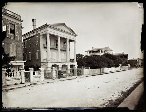
The photographs shows the house before the 1886 Charleston earthquake, in which the giant portico was demolished, leaving only its base. The photograph shows the house with the Tower of the Winds portico intact, featuring four Corinthian Capitals modelled after the Tower of the Winds, a time keeping tower, in Athens Greece. After the earthquake, the columns were buried in the back yard.
PH1984:0977:614
Description:
The photographs shows the house before the 1886 Charleston earthquake, in which the giant portico was demolished, leaving only its base. The photograph shows the house with the Tower of the Winds portico intact, featuring four Corinthian Capitals modelled after the Tower of the Winds, a time keeping tower, in Athens Greece. After the earthquake, the columns were buried in the back yard.
Personnes et institutions:
Date:
ca. 1860-1886
ca. 1860-1886
Titre:
View of the William Ravenel house, 13 East Battery, Charleston, South Carolina, United States of America
Actions:
PH1984:0977:614
Description:
The photographs shows the house before the 1886 Charleston earthquake, in which the giant portico was demolished, leaving only its base. The photograph shows the house with the Tower of the Winds portico intact, featuring four Corinthian Capitals modelled after the Tower of the Winds, a time keeping tower, in Athens Greece. After the earthquake, the columns were buried in the back yard.
View of the William Ravenel house, 13 East Battery, Charleston, South Carolina, United States of America
Actions:
PH1984:0977:614
Description:
The photographs shows the house before the 1886 Charleston earthquake, in which the giant portico was demolished, leaving only its base. The photograph shows the house with the Tower of the Winds portico intact, featuring four Corinthian Capitals modelled after the Tower of the Winds, a time keeping tower, in Athens Greece. After the earthquake, the columns were buried in the back yard.
Classification:
photographies
photographies
Date:
ca. 1860-1886
ca. 1860-1886
Personnes et institutions:


