


11176 Résultats
Classification:
dessins
Quantité:
25 drawing(s)
dessins
Quantité:
25 drawing(s)
Numéro de référence:
DR2004:0989
Description:
views of site, sections, conceptual sketches, site plans, design development drawings, possibly presentation drawings, perspectives, plans, diagrams, reference drawings, clippings, axonometric, sketch possibly from the Button Hole project, brochure from the Afella project, and notes
DR2004:0989
Description:
views of site, sections, conceptual sketches, site plans, design development drawings, possibly presentation drawings, perspectives, plans, diagrams, reference drawings, clippings, axonometric, sketch possibly from the Button Hole project, brochure from the Afella project, and notes
Personnes et institutions:
Titre:
Views of site, sections, conceptual sketches, site plans
Actions:
DR2004:0989
Description:
views of site, sections, conceptual sketches, site plans, design development drawings, possibly presentation drawings, perspectives, plans, diagrams, reference drawings, clippings, axonometric, sketch possibly from the Button Hole project, brochure from the Afella project, and notes
Views of site, sections, conceptual sketches, site plans
Actions:
DR2004:0989
Description:
views of site, sections, conceptual sketches, site plans, design development drawings, possibly presentation drawings, perspectives, plans, diagrams, reference drawings, clippings, axonometric, sketch possibly from the Button Hole project, brochure from the Afella project, and notes
Classification:
dessins
Quantité:
25 drawing(s)
dessins
Quantité:
25 drawing(s)
Personnes et institutions:
Classification:
archives
Niveau de description archivistique:
Fonds
archives
Niveau de description archivistique:
Fonds
Titre:
Fonds Peter Carter
Fonds Peter Carter
Numéro de référence:
AP047
Résumé:
The Peter Carter fonds, 1943-1996, documents the professional career of architect Peter Carter. The largest portion of the archive corresponds to projects Carter completed as principal of the office, Peter Carter Architect (1974-96). Materials in this fonds consist of 7263 drawings (including reprographic copies), 2007 photographic materials, approximately 65 panels, 3 l.m. of textual records, 26 models, 1 enclosing unit, 1 carpet sample, 1 graphic design layout for stationery letterhead, 1 brown oak sample, 1 window sample, 1 sign, 1 carioca stone, 1 travertine block and 1 grey carpet tile.
AP047
Résumé:
The Peter Carter fonds, 1943-1996, documents the professional career of architect Peter Carter. The largest portion of the archive corresponds to projects Carter completed as principal of the office, Peter Carter Architect (1974-96). Materials in this fonds consist of 7263 drawings (including reprographic copies), 2007 photographic materials, approximately 65 panels, 3 l.m. of textual records, 26 models, 1 enclosing unit, 1 carpet sample, 1 graphic design layout for stationery letterhead, 1 brown oak sample, 1 window sample, 1 sign, 1 carioca stone, 1 travertine block and 1 grey carpet tile.
Personnes et institutions:
Date:
1943-1996
1943-1996
Titre:
Fonds Peter Carter
Actions:
AP047
Résumé:
The Peter Carter fonds, 1943-1996, documents the professional career of architect Peter Carter. The largest portion of the archive corresponds to projects Carter completed as principal of the office, Peter Carter Architect (1974-96). Materials in this fonds consist of 7263 drawings (including reprographic copies), 2007 photographic materials, approximately 65 panels, 3 l.m. of textual records, 26 models, 1 enclosing unit, 1 carpet sample, 1 graphic design layout for stationery letterhead, 1 brown oak sample, 1 window sample, 1 sign, 1 carioca stone, 1 travertine block and 1 grey carpet tile.
Fonds Peter Carter
Actions:
AP047
Résumé:
The Peter Carter fonds, 1943-1996, documents the professional career of architect Peter Carter. The largest portion of the archive corresponds to projects Carter completed as principal of the office, Peter Carter Architect (1974-96). Materials in this fonds consist of 7263 drawings (including reprographic copies), 2007 photographic materials, approximately 65 panels, 3 l.m. of textual records, 26 models, 1 enclosing unit, 1 carpet sample, 1 graphic design layout for stationery letterhead, 1 brown oak sample, 1 window sample, 1 sign, 1 carioca stone, 1 travertine block and 1 grey carpet tile.
Classification:
archives
Niveau de description archivistique:
Fonds
archives
Niveau de description archivistique:
Fonds
Date:
1943-1996
1943-1996
Personnes et institutions:
Actions:
Numéro de référence:
DR1998:0148
Description:
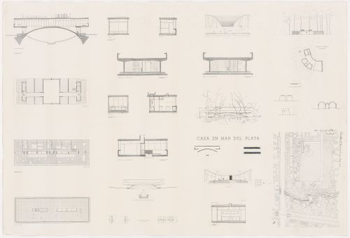
Dérouler par la conservation pour un traitement de moississure. Roll #15 (1 sheet) - Amancio Williams "Casa en Mar del Plata" (1945) - site plan, plans, elevations, sections, perspectives (inscribed: dedication to Reginald and Margaret Malcolmson, 1978, AW), print, 29 x 42"
DR1998:0148
Description:
Dérouler par la conservation pour un traitement de moississure. Roll #15 (1 sheet) - Amancio Williams "Casa en Mar del Plata" (1945) - site plan, plans, elevations, sections, perspectives (inscribed: dedication to Reginald and Margaret Malcolmson, 1978, AW), print, 29 x 42"
Personnes et institutions:
Date:
1945
1945
Titre:
Presentation drawing for Casa en Mar del Plata
Actions:
DR1998:0148
Description:
Dérouler par la conservation pour un traitement de moississure. Roll #15 (1 sheet) - Amancio Williams "Casa en Mar del Plata" (1945) - site plan, plans, elevations, sections, perspectives (inscribed: dedication to Reginald and Margaret Malcolmson, 1978, AW), print, 29 x 42"
Presentation drawing for Casa en Mar del Plata
Actions:
DR1998:0148
Description:
Dérouler par la conservation pour un traitement de moississure. Roll #15 (1 sheet) - Amancio Williams "Casa en Mar del Plata" (1945) - site plan, plans, elevations, sections, perspectives (inscribed: dedication to Reginald and Margaret Malcolmson, 1978, AW), print, 29 x 42"
Date:
1945
1945
Personnes et institutions:
Classification:
dessins
Quantité:
62 conceptual drawing(s)
dessins
Quantité:
62 conceptual drawing(s)
Numéro de référence:
DR2004:0897
Description:
elevations, some with annotations, sections, sketches, perspectives, engineer's drawings, views of railway bridges, views of site, photomontages, design development drawings, postcards, montages, presentation drawings, details, maps, overlays, notes, clippings, land survey, plan, site plan, and diagram
DR2004:0897
Description:
elevations, some with annotations, sections, sketches, perspectives, engineer's drawings, views of railway bridges, views of site, photomontages, design development drawings, postcards, montages, presentation drawings, details, maps, overlays, notes, clippings, land survey, plan, site plan, and diagram
Personnes et institutions:
Titre:
Elevations, some with annotations, sections, sketches
Actions:
DR2004:0897
Description:
elevations, some with annotations, sections, sketches, perspectives, engineer's drawings, views of railway bridges, views of site, photomontages, design development drawings, postcards, montages, presentation drawings, details, maps, overlays, notes, clippings, land survey, plan, site plan, and diagram
Elevations, some with annotations, sections, sketches
Actions:
DR2004:0897
Description:
elevations, some with annotations, sections, sketches, perspectives, engineer's drawings, views of railway bridges, views of site, photomontages, design development drawings, postcards, montages, presentation drawings, details, maps, overlays, notes, clippings, land survey, plan, site plan, and diagram
Classification:
dessins
Quantité:
62 conceptual drawing(s)
dessins
Quantité:
62 conceptual drawing(s)
Personnes et institutions:
Classification:
dessins
Quantité:
16 File
dessins
Quantité:
16 File
Numéro de référence:
ARCH39793
Description:
kitchen layout, health unit, distribution centres, service elevator, location of garage, publication plan, cafeteria partition, perspectives of cafeteria and conference room, plans and elevations of conference room, window, chair design, conference table, waste paper room, entrance hall
ARCH39793
Description:
kitchen layout, health unit, distribution centres, service elevator, location of garage, publication plan, cafeteria partition, perspectives of cafeteria and conference room, plans and elevations of conference room, window, chair design, conference table, waste paper room, entrance hall
Personnes et institutions:
Titre:
Kitchen layout, health unit, distribution centres, service elevator, location of garage, publication plan
Actions:
ARCH39793
Description:
kitchen layout, health unit, distribution centres, service elevator, location of garage, publication plan, cafeteria partition, perspectives of cafeteria and conference room, plans and elevations of conference room, window, chair design, conference table, waste paper room, entrance hall
Kitchen layout, health unit, distribution centres, service elevator, location of garage, publication plan
Actions:
ARCH39793
Description:
kitchen layout, health unit, distribution centres, service elevator, location of garage, publication plan, cafeteria partition, perspectives of cafeteria and conference room, plans and elevations of conference room, window, chair design, conference table, waste paper room, entrance hall
Classification:
dessins
Quantité:
16 File
dessins
Quantité:
16 File
Personnes et institutions:
Classification:
dessins
Quantité:
227 design development drawing(s)
dessins
Quantité:
227 design development drawing(s)
Numéro de référence:
DR2004:0602
Description:
sketches, conceptual drawings, measured sketches, sections, site plans, details, perspectives, schematics, diagrams, schedules, reference drawings, photographs of London Bridge Station, axonometrics, elevations, notes, consultant's drawings, maps, clippings, computer drawings, captions, and sketch from the Serre project
DR2004:0602
Description:
sketches, conceptual drawings, measured sketches, sections, site plans, details, perspectives, schematics, diagrams, schedules, reference drawings, photographs of London Bridge Station, axonometrics, elevations, notes, consultant's drawings, maps, clippings, computer drawings, captions, and sketch from the Serre project
Personnes et institutions:
Titre:
Sketches, conceptual drawings, measured sketches, sections, site plans, details
Actions:
DR2004:0602
Description:
sketches, conceptual drawings, measured sketches, sections, site plans, details, perspectives, schematics, diagrams, schedules, reference drawings, photographs of London Bridge Station, axonometrics, elevations, notes, consultant's drawings, maps, clippings, computer drawings, captions, and sketch from the Serre project
Sketches, conceptual drawings, measured sketches, sections, site plans, details
Actions:
DR2004:0602
Description:
sketches, conceptual drawings, measured sketches, sections, site plans, details, perspectives, schematics, diagrams, schedules, reference drawings, photographs of London Bridge Station, axonometrics, elevations, notes, consultant's drawings, maps, clippings, computer drawings, captions, and sketch from the Serre project
Classification:
dessins
Quantité:
227 design development drawing(s)
dessins
Quantité:
227 design development drawing(s)
Personnes et institutions:
Niveau de description archivistique:
Série(s)
Série(s)
Titre:
Architectural projects
Architectural projects
Numéro de référence:
AP018.S1
Description:
The Architectural Projects series, 1945-1986, is the largest series in the fonds and documents the projects worked on by Parkin’s two firms throughout his career. These projects include built work, urban planning, proposals, competitions and feasibility studies. The majority of the projects were based in Toronto and the surrounding area, but projects from across Canada and some international projects in the Caribbean, Middle East, and Northern Africa are also included. These individual projects were identified and separated based on distinct project numbers assigned by the creating offices. The general numbering rule at the offices was two digits to represent the year, followed by two or three digits to represent the consecutive project number for that year (YY###). For instance the 7th project taken on in the year 1980 would be assigned the project number 8007. This chronological ordering has been respected in the arrangement of this series. These projects are recorded primarily through textual records and drawings, but some photographs, paintings, artefacts and one book are also included in this series. The amount of drawings and textual materials for the projects vary greatly. Materials for projects before 1971, from the firm John B. Parkin Associates, are very sparse, sometimes with only a few files or drawings representing a project. Materials after 1971, from the firm Parkin Architects Planners, are much more complete and often contain drawings from initial sketches to finished construction work. Among these drawings are plans, elevations, sections, details, perspectives, and mechanical, electrical and structural drawings. Textual records for these projects typically include correspondence, meeting minutes, specifications, site reports, consultancy files and other construction documentation. The photographic materials in this series often show construction progress and completed work. Also present are presentation panels with mounted drawings, photographs and paintings for some projects. The artefacts typically consist of material samples for construction. The textual records for projects are almost always in English, but some drawings are in French or are bilingual for projects commissioned by the Government of Canada. Although John C. Parkin is the creator of this series, the partners at his firms and other employees played a significant role as creators of the contents. Especially in the material from Parkin Architects Planners, the names of his partners such as J.B. Mar, P.H. Warren, D.L. Wilson, and L. Payne are often marked as authors of the materials.
AP018.S1
Description:
The Architectural Projects series, 1945-1986, is the largest series in the fonds and documents the projects worked on by Parkin’s two firms throughout his career. These projects include built work, urban planning, proposals, competitions and feasibility studies. The majority of the projects were based in Toronto and the surrounding area, but projects from across Canada and some international projects in the Caribbean, Middle East, and Northern Africa are also included. These individual projects were identified and separated based on distinct project numbers assigned by the creating offices. The general numbering rule at the offices was two digits to represent the year, followed by two or three digits to represent the consecutive project number for that year (YY###). For instance the 7th project taken on in the year 1980 would be assigned the project number 8007. This chronological ordering has been respected in the arrangement of this series. These projects are recorded primarily through textual records and drawings, but some photographs, paintings, artefacts and one book are also included in this series. The amount of drawings and textual materials for the projects vary greatly. Materials for projects before 1971, from the firm John B. Parkin Associates, are very sparse, sometimes with only a few files or drawings representing a project. Materials after 1971, from the firm Parkin Architects Planners, are much more complete and often contain drawings from initial sketches to finished construction work. Among these drawings are plans, elevations, sections, details, perspectives, and mechanical, electrical and structural drawings. Textual records for these projects typically include correspondence, meeting minutes, specifications, site reports, consultancy files and other construction documentation. The photographic materials in this series often show construction progress and completed work. Also present are presentation panels with mounted drawings, photographs and paintings for some projects. The artefacts typically consist of material samples for construction. The textual records for projects are almost always in English, but some drawings are in French or are bilingual for projects commissioned by the Government of Canada. Although John C. Parkin is the creator of this series, the partners at his firms and other employees played a significant role as creators of the contents. Especially in the material from Parkin Architects Planners, the names of his partners such as J.B. Mar, P.H. Warren, D.L. Wilson, and L. Payne are often marked as authors of the materials.
Personnes et institutions:
Date:
1945-1986
1945-1986
Titre:
Architectural projects
Actions:
AP018.S1
Description:
The Architectural Projects series, 1945-1986, is the largest series in the fonds and documents the projects worked on by Parkin’s two firms throughout his career. These projects include built work, urban planning, proposals, competitions and feasibility studies. The majority of the projects were based in Toronto and the surrounding area, but projects from across Canada and some international projects in the Caribbean, Middle East, and Northern Africa are also included. These individual projects were identified and separated based on distinct project numbers assigned by the creating offices. The general numbering rule at the offices was two digits to represent the year, followed by two or three digits to represent the consecutive project number for that year (YY###). For instance the 7th project taken on in the year 1980 would be assigned the project number 8007. This chronological ordering has been respected in the arrangement of this series. These projects are recorded primarily through textual records and drawings, but some photographs, paintings, artefacts and one book are also included in this series. The amount of drawings and textual materials for the projects vary greatly. Materials for projects before 1971, from the firm John B. Parkin Associates, are very sparse, sometimes with only a few files or drawings representing a project. Materials after 1971, from the firm Parkin Architects Planners, are much more complete and often contain drawings from initial sketches to finished construction work. Among these drawings are plans, elevations, sections, details, perspectives, and mechanical, electrical and structural drawings. Textual records for these projects typically include correspondence, meeting minutes, specifications, site reports, consultancy files and other construction documentation. The photographic materials in this series often show construction progress and completed work. Also present are presentation panels with mounted drawings, photographs and paintings for some projects. The artefacts typically consist of material samples for construction. The textual records for projects are almost always in English, but some drawings are in French or are bilingual for projects commissioned by the Government of Canada. Although John C. Parkin is the creator of this series, the partners at his firms and other employees played a significant role as creators of the contents. Especially in the material from Parkin Architects Planners, the names of his partners such as J.B. Mar, P.H. Warren, D.L. Wilson, and L. Payne are often marked as authors of the materials.
Architectural projects
Actions:
AP018.S1
Description:
The Architectural Projects series, 1945-1986, is the largest series in the fonds and documents the projects worked on by Parkin’s two firms throughout his career. These projects include built work, urban planning, proposals, competitions and feasibility studies. The majority of the projects were based in Toronto and the surrounding area, but projects from across Canada and some international projects in the Caribbean, Middle East, and Northern Africa are also included. These individual projects were identified and separated based on distinct project numbers assigned by the creating offices. The general numbering rule at the offices was two digits to represent the year, followed by two or three digits to represent the consecutive project number for that year (YY###). For instance the 7th project taken on in the year 1980 would be assigned the project number 8007. This chronological ordering has been respected in the arrangement of this series. These projects are recorded primarily through textual records and drawings, but some photographs, paintings, artefacts and one book are also included in this series. The amount of drawings and textual materials for the projects vary greatly. Materials for projects before 1971, from the firm John B. Parkin Associates, are very sparse, sometimes with only a few files or drawings representing a project. Materials after 1971, from the firm Parkin Architects Planners, are much more complete and often contain drawings from initial sketches to finished construction work. Among these drawings are plans, elevations, sections, details, perspectives, and mechanical, electrical and structural drawings. Textual records for these projects typically include correspondence, meeting minutes, specifications, site reports, consultancy files and other construction documentation. The photographic materials in this series often show construction progress and completed work. Also present are presentation panels with mounted drawings, photographs and paintings for some projects. The artefacts typically consist of material samples for construction. The textual records for projects are almost always in English, but some drawings are in French or are bilingual for projects commissioned by the Government of Canada. Although John C. Parkin is the creator of this series, the partners at his firms and other employees played a significant role as creators of the contents. Especially in the material from Parkin Architects Planners, the names of his partners such as J.B. Mar, P.H. Warren, D.L. Wilson, and L. Payne are often marked as authors of the materials.
Niveau de description archivistique:
Series
Series
Date:
1945-1986
1945-1986
Personnes et institutions:
Niveau de description archivistique:
Projet
Projet
Numéro de référence:
AP056.S1.1989.PR08
Description:
This project series documents the winning competition entry and subsequent construction for Kitchener City Hall in Kitchener, Ontario from 1989-1993. The office identified the project number as 8928. This project consisted of a U-shaped civic building comprised of a circular rotunda in the centre, an office tower to the right, the council chambers to the left, and two rectangular arms on either side to create the arms of the U. These elements, which wrapped around a large reflecting pool that doubled as a skating rink, were visually separated but coherent in their design and use of materials. Located on the block between Young, College, Duke and King Streets, the interior and exteriors of the property were designed for city government, but also for the larger public with community, public spaces, and open interaction with local government as key design concepts for the project. After entering the Civic Square outside the building, patrons can pass through the main portico, into the Interior Civic Square were the round Civic Rotunda rests in the centre. The rotunda’s interior was designed for use as a public gathering space, where events and activities could be held. The top of the rotunda had sandblasted glass windows with patinated copper frames, letting natural light shine into the large space below. A staircase from the main Civic Square led to an exterior terrace that wrapped around the top of the rotunda. The Administrative Office Tower was ten-storeys with a mechanical penthouse, and was used for civic offices. The Council Chamber was comprised of limestone with refinished metal panels forming a curved roof on top. The two wings along the sides of the property contained tenant areas, a restaurant, information offices, alderman’s offices and the mayor’s office, among other spaces. The back of the property had landscaped exteriors and outdoor play areas for the building’s daycare. The project is recorded through drawings, photographic materials, presentation paintings and models dating from 1989-1993. The drawings consist of concepts for both the competition entry and the subsequent construction of the project. These include sketches, base maps and area surveys produced by the city and contractors, presentation boards and paintings, plans, elevations, sections, perspectives, details and axonometric drawings. There are also photographic reproductions of presentation drawings. The photographs show finished interiors and exteriors and the project model.
AP056.S1.1989.PR08
Description:
This project series documents the winning competition entry and subsequent construction for Kitchener City Hall in Kitchener, Ontario from 1989-1993. The office identified the project number as 8928. This project consisted of a U-shaped civic building comprised of a circular rotunda in the centre, an office tower to the right, the council chambers to the left, and two rectangular arms on either side to create the arms of the U. These elements, which wrapped around a large reflecting pool that doubled as a skating rink, were visually separated but coherent in their design and use of materials. Located on the block between Young, College, Duke and King Streets, the interior and exteriors of the property were designed for city government, but also for the larger public with community, public spaces, and open interaction with local government as key design concepts for the project. After entering the Civic Square outside the building, patrons can pass through the main portico, into the Interior Civic Square were the round Civic Rotunda rests in the centre. The rotunda’s interior was designed for use as a public gathering space, where events and activities could be held. The top of the rotunda had sandblasted glass windows with patinated copper frames, letting natural light shine into the large space below. A staircase from the main Civic Square led to an exterior terrace that wrapped around the top of the rotunda. The Administrative Office Tower was ten-storeys with a mechanical penthouse, and was used for civic offices. The Council Chamber was comprised of limestone with refinished metal panels forming a curved roof on top. The two wings along the sides of the property contained tenant areas, a restaurant, information offices, alderman’s offices and the mayor’s office, among other spaces. The back of the property had landscaped exteriors and outdoor play areas for the building’s daycare. The project is recorded through drawings, photographic materials, presentation paintings and models dating from 1989-1993. The drawings consist of concepts for both the competition entry and the subsequent construction of the project. These include sketches, base maps and area surveys produced by the city and contractors, presentation boards and paintings, plans, elevations, sections, perspectives, details and axonometric drawings. There are also photographic reproductions of presentation drawings. The photographs show finished interiors and exteriors and the project model.
Personnes et institutions:
Date:
1989-1993
1989-1993
Titre:
Kitchener City Hall Competition, Ontario (1989-1993)
Actions:
AP056.S1.1989.PR08
Description:
This project series documents the winning competition entry and subsequent construction for Kitchener City Hall in Kitchener, Ontario from 1989-1993. The office identified the project number as 8928. This project consisted of a U-shaped civic building comprised of a circular rotunda in the centre, an office tower to the right, the council chambers to the left, and two rectangular arms on either side to create the arms of the U. These elements, which wrapped around a large reflecting pool that doubled as a skating rink, were visually separated but coherent in their design and use of materials. Located on the block between Young, College, Duke and King Streets, the interior and exteriors of the property were designed for city government, but also for the larger public with community, public spaces, and open interaction with local government as key design concepts for the project. After entering the Civic Square outside the building, patrons can pass through the main portico, into the Interior Civic Square were the round Civic Rotunda rests in the centre. The rotunda’s interior was designed for use as a public gathering space, where events and activities could be held. The top of the rotunda had sandblasted glass windows with patinated copper frames, letting natural light shine into the large space below. A staircase from the main Civic Square led to an exterior terrace that wrapped around the top of the rotunda. The Administrative Office Tower was ten-storeys with a mechanical penthouse, and was used for civic offices. The Council Chamber was comprised of limestone with refinished metal panels forming a curved roof on top. The two wings along the sides of the property contained tenant areas, a restaurant, information offices, alderman’s offices and the mayor’s office, among other spaces. The back of the property had landscaped exteriors and outdoor play areas for the building’s daycare. The project is recorded through drawings, photographic materials, presentation paintings and models dating from 1989-1993. The drawings consist of concepts for both the competition entry and the subsequent construction of the project. These include sketches, base maps and area surveys produced by the city and contractors, presentation boards and paintings, plans, elevations, sections, perspectives, details and axonometric drawings. There are also photographic reproductions of presentation drawings. The photographs show finished interiors and exteriors and the project model.
Kitchener City Hall Competition, Ontario (1989-1993)
Actions:
AP056.S1.1989.PR08
Description:
This project series documents the winning competition entry and subsequent construction for Kitchener City Hall in Kitchener, Ontario from 1989-1993. The office identified the project number as 8928. This project consisted of a U-shaped civic building comprised of a circular rotunda in the centre, an office tower to the right, the council chambers to the left, and two rectangular arms on either side to create the arms of the U. These elements, which wrapped around a large reflecting pool that doubled as a skating rink, were visually separated but coherent in their design and use of materials. Located on the block between Young, College, Duke and King Streets, the interior and exteriors of the property were designed for city government, but also for the larger public with community, public spaces, and open interaction with local government as key design concepts for the project. After entering the Civic Square outside the building, patrons can pass through the main portico, into the Interior Civic Square were the round Civic Rotunda rests in the centre. The rotunda’s interior was designed for use as a public gathering space, where events and activities could be held. The top of the rotunda had sandblasted glass windows with patinated copper frames, letting natural light shine into the large space below. A staircase from the main Civic Square led to an exterior terrace that wrapped around the top of the rotunda. The Administrative Office Tower was ten-storeys with a mechanical penthouse, and was used for civic offices. The Council Chamber was comprised of limestone with refinished metal panels forming a curved roof on top. The two wings along the sides of the property contained tenant areas, a restaurant, information offices, alderman’s offices and the mayor’s office, among other spaces. The back of the property had landscaped exteriors and outdoor play areas for the building’s daycare. The project is recorded through drawings, photographic materials, presentation paintings and models dating from 1989-1993. The drawings consist of concepts for both the competition entry and the subsequent construction of the project. These include sketches, base maps and area surveys produced by the city and contractors, presentation boards and paintings, plans, elevations, sections, perspectives, details and axonometric drawings. There are also photographic reproductions of presentation drawings. The photographs show finished interiors and exteriors and the project model.
Niveau de description archivistique:
Project
Project
Date:
1989-1993
1989-1993
Personnes et institutions:
Niveau de description archivistique:
Projet
Projet
Titre:
O.C.H. Feasibility Study
O.C.H. Feasibility Study
Numéro de référence:
AP144.S2.D59
Description:
File documents a feasibility study commissioned by J. Lyons Co. Ltd for the conversion of the Oxford Corner House, in London, England, United Kingdom, into a combined information, education and skill centre. The unrealized project was to include a 'self-pace public skill and information hive' with facilities for conferences, teaching, exhibitions, computer use, planetarium, audio-visual library, and public eating areas. The project included a movable floor system and projection screens. Reference material includes plans and details of London Electric Railway subway line, alterations to Oxford Street Corner House by J. Lyons and Co. Ltd., field notes, photographs and photomontages of site. Conceptual diagrammatic plans explore designs for the organization of activities. Charts show variables, including number of people, monitors/screens, and study carrels; circulation patterns; and maximization of viewing capacity. Preliminary presentation boards illustrate project feasibility and include photographs of model and existing conditions. Design development drawings include floor plans, plans exploring the relationships between various activities, analysis of building volumes and networks, comparative plans showing main structural grid, sections, diagrammatic sections for public activity areas, axonometric drawings of roof, perspectives of projection screens and moveable floor system, progress charts, and diagrams and graphs of communication and travel modes, routes, and time into central London from outlying areas. Some material in this file was published in Price, Cedric. 'Cedric Price-Works II' (London: Architectural Press, 1984), 11, 54, 112; Landau, Royston. 'New Directions in British Architecture'. New York: George Braziller, 1968. 108-111; and 'Self-Pace Public Skill and Information Hive.' 'Architectural Design'. (May 1968), 237-239. Material in this file was produced between 1927 and 1967, but predominantly between 1965 and 1966. Group DR1995:0224:001-013 contains reference drawings attributed to London Transport Architect's Department and J. Lyons & Company Limited Architect's Office. Group DR1995:0224:333-341 contains drawings attributed to Richard Sutcliffe Limited, Felix J. Samuely & Partners, and G.E.C. (Process Engineering) Ltd. File contains conceptual drawings, consultant drawings, design development drawings, presentation drawings, presentation panels, reference drawings, photographic material, and textual records.
AP144.S2.D59
Description:
File documents a feasibility study commissioned by J. Lyons Co. Ltd for the conversion of the Oxford Corner House, in London, England, United Kingdom, into a combined information, education and skill centre. The unrealized project was to include a 'self-pace public skill and information hive' with facilities for conferences, teaching, exhibitions, computer use, planetarium, audio-visual library, and public eating areas. The project included a movable floor system and projection screens. Reference material includes plans and details of London Electric Railway subway line, alterations to Oxford Street Corner House by J. Lyons and Co. Ltd., field notes, photographs and photomontages of site. Conceptual diagrammatic plans explore designs for the organization of activities. Charts show variables, including number of people, monitors/screens, and study carrels; circulation patterns; and maximization of viewing capacity. Preliminary presentation boards illustrate project feasibility and include photographs of model and existing conditions. Design development drawings include floor plans, plans exploring the relationships between various activities, analysis of building volumes and networks, comparative plans showing main structural grid, sections, diagrammatic sections for public activity areas, axonometric drawings of roof, perspectives of projection screens and moveable floor system, progress charts, and diagrams and graphs of communication and travel modes, routes, and time into central London from outlying areas. Some material in this file was published in Price, Cedric. 'Cedric Price-Works II' (London: Architectural Press, 1984), 11, 54, 112; Landau, Royston. 'New Directions in British Architecture'. New York: George Braziller, 1968. 108-111; and 'Self-Pace Public Skill and Information Hive.' 'Architectural Design'. (May 1968), 237-239. Material in this file was produced between 1927 and 1967, but predominantly between 1965 and 1966. Group DR1995:0224:001-013 contains reference drawings attributed to London Transport Architect's Department and J. Lyons & Company Limited Architect's Office. Group DR1995:0224:333-341 contains drawings attributed to Richard Sutcliffe Limited, Felix J. Samuely & Partners, and G.E.C. (Process Engineering) Ltd. File contains conceptual drawings, consultant drawings, design development drawings, presentation drawings, presentation panels, reference drawings, photographic material, and textual records.
Personnes et institutions:
Date:
1927-1967, predominant 1965-1966
1927-1967, predominant 1965-1966
Titre:
O.C.H. Feasibility Study
Actions:
AP144.S2.D59
Description:
File documents a feasibility study commissioned by J. Lyons Co. Ltd for the conversion of the Oxford Corner House, in London, England, United Kingdom, into a combined information, education and skill centre. The unrealized project was to include a 'self-pace public skill and information hive' with facilities for conferences, teaching, exhibitions, computer use, planetarium, audio-visual library, and public eating areas. The project included a movable floor system and projection screens. Reference material includes plans and details of London Electric Railway subway line, alterations to Oxford Street Corner House by J. Lyons and Co. Ltd., field notes, photographs and photomontages of site. Conceptual diagrammatic plans explore designs for the organization of activities. Charts show variables, including number of people, monitors/screens, and study carrels; circulation patterns; and maximization of viewing capacity. Preliminary presentation boards illustrate project feasibility and include photographs of model and existing conditions. Design development drawings include floor plans, plans exploring the relationships between various activities, analysis of building volumes and networks, comparative plans showing main structural grid, sections, diagrammatic sections for public activity areas, axonometric drawings of roof, perspectives of projection screens and moveable floor system, progress charts, and diagrams and graphs of communication and travel modes, routes, and time into central London from outlying areas. Some material in this file was published in Price, Cedric. 'Cedric Price-Works II' (London: Architectural Press, 1984), 11, 54, 112; Landau, Royston. 'New Directions in British Architecture'. New York: George Braziller, 1968. 108-111; and 'Self-Pace Public Skill and Information Hive.' 'Architectural Design'. (May 1968), 237-239. Material in this file was produced between 1927 and 1967, but predominantly between 1965 and 1966. Group DR1995:0224:001-013 contains reference drawings attributed to London Transport Architect's Department and J. Lyons & Company Limited Architect's Office. Group DR1995:0224:333-341 contains drawings attributed to Richard Sutcliffe Limited, Felix J. Samuely & Partners, and G.E.C. (Process Engineering) Ltd. File contains conceptual drawings, consultant drawings, design development drawings, presentation drawings, presentation panels, reference drawings, photographic material, and textual records.
O.C.H. Feasibility Study
Actions:
AP144.S2.D59
Description:
File documents a feasibility study commissioned by J. Lyons Co. Ltd for the conversion of the Oxford Corner House, in London, England, United Kingdom, into a combined information, education and skill centre. The unrealized project was to include a 'self-pace public skill and information hive' with facilities for conferences, teaching, exhibitions, computer use, planetarium, audio-visual library, and public eating areas. The project included a movable floor system and projection screens. Reference material includes plans and details of London Electric Railway subway line, alterations to Oxford Street Corner House by J. Lyons and Co. Ltd., field notes, photographs and photomontages of site. Conceptual diagrammatic plans explore designs for the organization of activities. Charts show variables, including number of people, monitors/screens, and study carrels; circulation patterns; and maximization of viewing capacity. Preliminary presentation boards illustrate project feasibility and include photographs of model and existing conditions. Design development drawings include floor plans, plans exploring the relationships between various activities, analysis of building volumes and networks, comparative plans showing main structural grid, sections, diagrammatic sections for public activity areas, axonometric drawings of roof, perspectives of projection screens and moveable floor system, progress charts, and diagrams and graphs of communication and travel modes, routes, and time into central London from outlying areas. Some material in this file was published in Price, Cedric. 'Cedric Price-Works II' (London: Architectural Press, 1984), 11, 54, 112; Landau, Royston. 'New Directions in British Architecture'. New York: George Braziller, 1968. 108-111; and 'Self-Pace Public Skill and Information Hive.' 'Architectural Design'. (May 1968), 237-239. Material in this file was produced between 1927 and 1967, but predominantly between 1965 and 1966. Group DR1995:0224:001-013 contains reference drawings attributed to London Transport Architect's Department and J. Lyons & Company Limited Architect's Office. Group DR1995:0224:333-341 contains drawings attributed to Richard Sutcliffe Limited, Felix J. Samuely & Partners, and G.E.C. (Process Engineering) Ltd. File contains conceptual drawings, consultant drawings, design development drawings, presentation drawings, presentation panels, reference drawings, photographic material, and textual records.
Niveau de description archivistique:
File 59
File 59
Date:
1927-1967, predominant 1965-1966
1927-1967, predominant 1965-1966
Personnes et institutions:
Classification:
dessins
Quantité:
53 conceptual drawing(s)
dessins
Quantité:
53 conceptual drawing(s)
Numéro de référence:
DR1998:0054:001-053
Description:
sketches, including sketch plans, sketch elevations, sketch sections, sketch axonometrics, sketch perspectives and sketch details; includes reprographic copies of typewritten texts, predominantly portions of the exhibition notes for 'An Exhibition of 23 Paintings by John Q. Hejduk', dated 1955
DR1998:0054:001-053
Description:
sketches, including sketch plans, sketch elevations, sketch sections, sketch axonometrics, sketch perspectives and sketch details; includes reprographic copies of typewritten texts, predominantly portions of the exhibition notes for 'An Exhibition of 23 Paintings by John Q. Hejduk', dated 1955
Personnes et institutions:
Titre:
Sketches, including sketch plans, sketch elevations
Actions:
DR1998:0054:001-053
Description:
sketches, including sketch plans, sketch elevations, sketch sections, sketch axonometrics, sketch perspectives and sketch details; includes reprographic copies of typewritten texts, predominantly portions of the exhibition notes for 'An Exhibition of 23 Paintings by John Q. Hejduk', dated 1955
Sketches, including sketch plans, sketch elevations
Actions:
DR1998:0054:001-053
Description:
sketches, including sketch plans, sketch elevations, sketch sections, sketch axonometrics, sketch perspectives and sketch details; includes reprographic copies of typewritten texts, predominantly portions of the exhibition notes for 'An Exhibition of 23 Paintings by John Q. Hejduk', dated 1955
Classification:
dessins
Quantité:
53 conceptual drawing(s)
dessins
Quantité:
53 conceptual drawing(s)
Personnes et institutions:


