


4344 Résultats
Classification:
photographies
photographies
Numéro de référence:
ARCH268584
Description:
Contains photographic materials on 3 projects by Abalos & Herreros: - Exposición Coam, AP164.S2.SS1.D2 (3 colour reversal films: interior views of the exhibition) - Concurso Embajada de Francia, AP164.S1.1991.D1 (5 colour slides: model) - Palencia Parque Europa, AP164.S1.1991.D2 (281 slides, 9 colour reversal films, 2 chromogenic colour prints: exterior views, perspectives, plans, model, aerial views) Several images were taken by Juan Merimero.
ARCH268584
Description:
Contains photographic materials on 3 projects by Abalos & Herreros: - Exposición Coam, AP164.S2.SS1.D2 (3 colour reversal films: interior views of the exhibition) - Concurso Embajada de Francia, AP164.S1.1991.D1 (5 colour slides: model) - Palencia Parque Europa, AP164.S1.1991.D2 (281 slides, 9 colour reversal films, 2 chromogenic colour prints: exterior views, perspectives, plans, model, aerial views) Several images were taken by Juan Merimero.
Personnes et institutions:
Date:
1990-1991
1990-1991
Titre:
Ring binder with photographic materials related to three projects by Abalos & Herreros
Actions:
ARCH268584
Description:
Contains photographic materials on 3 projects by Abalos & Herreros: - Exposición Coam, AP164.S2.SS1.D2 (3 colour reversal films: interior views of the exhibition) - Concurso Embajada de Francia, AP164.S1.1991.D1 (5 colour slides: model) - Palencia Parque Europa, AP164.S1.1991.D2 (281 slides, 9 colour reversal films, 2 chromogenic colour prints: exterior views, perspectives, plans, model, aerial views) Several images were taken by Juan Merimero.
Ring binder with photographic materials related to three projects by Abalos & Herreros
Actions:
ARCH268584
Description:
Contains photographic materials on 3 projects by Abalos & Herreros: - Exposición Coam, AP164.S2.SS1.D2 (3 colour reversal films: interior views of the exhibition) - Concurso Embajada de Francia, AP164.S1.1991.D1 (5 colour slides: model) - Palencia Parque Europa, AP164.S1.1991.D2 (281 slides, 9 colour reversal films, 2 chromogenic colour prints: exterior views, perspectives, plans, model, aerial views) Several images were taken by Juan Merimero.
Classification:
photographies
photographies
Date:
1990-1991
1990-1991
Personnes et institutions:
Classification:
photographies
photographies
Numéro de référence:
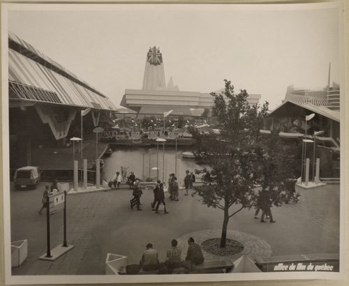
ARCH255841
ARCH255841
Personnes et institutions:
Date:
1967
1967
Classification:
photographies
photographies
Date:
1967
1967
Personnes et institutions:
Classification:
expositions
expositions
Actions:
Description:
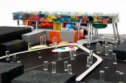
L’exposition présente les œuvres de l’architecte britannique Will Alsop, préparatoires au Sharp Centre for Design de l’Ontario College of Art and Design (OCAD) de Toronto, et s’attache en particulier au rôle qu’a joué la peinture dans son processus de création. La construction du Sharp Centre for Design de l’OCAD, conçu en collaboration avec Robbie/Young + Wright, s’est(...)
L’exposition présente les œuvres de l’architecte britannique Will Alsop, préparatoires au Sharp Centre for Design de l’Ontario College of Art and Design (OCAD) de Toronto, et s’attache en particulier au rôle qu’a joué la peinture dans son processus de création. La construction du Sharp Centre for Design de l’OCAD, conçu en collaboration avec Robbie/Young + Wright, s’est(...)
Localisation:
Salle octogonale
Salle octogonale
Date:
13 juin 2008 au 5 octobre 2008
13 juin 2008 au 5 octobre 2008
Titre:
Will Alsop : OCAD, un manifeste urbain
Actions:
Description:
L’exposition présente les œuvres de l’architecte britannique Will Alsop, préparatoires au Sharp Centre for Design de l’Ontario College of Art and Design (OCAD) de Toronto, et s’attache en particulier au rôle qu’a joué la peinture dans son processus de création. La construction du Sharp Centre for Design de l’OCAD, conçu en collaboration avec Robbie/Young + Wright, s’est(...)
Will Alsop : OCAD, un manifeste urbain
Actions:
Description:
L’exposition présente les œuvres de l’architecte britannique Will Alsop, préparatoires au Sharp Centre for Design de l’Ontario College of Art and Design (OCAD) de Toronto, et s’attache en particulier au rôle qu’a joué la peinture dans son processus de création. La construction du Sharp Centre for Design de l’OCAD, conçu en collaboration avec Robbie/Young + Wright, s’est(...)
Classification:
expositions
expositions
Date:
13 juin 2008 au
5 octobre 2008
13 juin 2008 au
5 octobre 2008
Localisation:
Salle octogonale
Salle octogonale
Numéro de référence:
ARCH257862
Description:
Boite en bois contenu des originaux enveloppes de photos, avec le sujet écrit sur l'enveloppe. Une boite en bois et portant l'inscription « France » et 2 autres boites ayant contenu des films, des diapositives, et des photos.
ARCH257862
Description:
Boite en bois contenu des originaux enveloppes de photos, avec le sujet écrit sur l'enveloppe. Une boite en bois et portant l'inscription « France » et 2 autres boites ayant contenu des films, des diapositives, et des photos.
Personnes et institutions:
Date:
1924-1936
1924-1936
Titre:
Boîtes en bois utilisées pour le rangement de photographies
Actions:
ARCH257862
Description:
Boite en bois contenu des originaux enveloppes de photos, avec le sujet écrit sur l'enveloppe. Une boite en bois et portant l'inscription « France » et 2 autres boites ayant contenu des films, des diapositives, et des photos.
Boîtes en bois utilisées pour le rangement de photographies
Actions:
ARCH257862
Description:
Boite en bois contenu des originaux enveloppes de photos, avec le sujet écrit sur l'enveloppe. Une boite en bois et portant l'inscription « France » et 2 autres boites ayant contenu des films, des diapositives, et des photos.
Date:
1924-1936
1924-1936
Personnes et institutions:
Niveau de description archivistique:
Projet
Projet
Titre:
Fun Palace Project
Fun Palace Project
Numéro de référence:
AP144.S2.D46
Description:
File documents the various unexecuted proposals for the Fun Palace Project, an interactive and adaptable, educational and cultural complex to be located in London, England. The project was commissioned by Joan Littlewood, to be erected on disused public land slated for redevelopment and intended to be dismantled after 10 years. Conceptual and design development drawings were created for a typical Fun Palace that could be erected on any suitable site, and several sites were considered, some belonging to the Civic Trust. Presentation drawings were elaborated for a Fun Palace in the Lea Valley at Mill Meads and for a later modified Pilot Project in Camden Town. Publication drawings were also created for an article in Price, Cedric. "Fun Palace Project." 'Architectural Review'. (January 1965), 74-75. The Fun Palace Trust was created to oversee the project and the file contains material from related activities of the Trust which was active until the 1970's. Existing conditions drawings begin in 1961 and include regional, zoning, and transportation maps of Greater London and a photocollage of the site. Conceptual and diagrammatic drawings include: perspectives for the structural system; plans for site access; charts for modular systems; axonometrics for modules; preliminary drawings for escalators and service towers; and studies for activity areas. A "Table of Kindred and Affinity" separates modular components physically and visually by means of activity types, circulation, and individual/group accommodations. Design development drawings for the Fun Palace Project include: plans for activity areas, site plans, typical plans, site movement/circulation plans, theatre seating plans, diagrammatic sections, volumetric structural diagrams, perspectives, charts for services for mass activities, typical mass activity enclosure types, charts for required equipment for activities, and "clamp" structural systems and studies for three dimensional versatility and modular feasibility. Design development drawings for the 1963 Camden Town Pilot Project include: site plans; diagrammatic plans showing circulation patterns; drawings showing basic cubes with components and structural panel types; details for component connections; charts for individual activity module requirements; and network analysis charts. Presentation material includes: aerial photographs mounted on board; enlargements of clippings; reprographic copies of photographs of the design models. Material in this file was created between 1961 and 1985 but predominantly between 1961 and 1974. File contains conceptual drawings, design development drawings, presentation drawings and panels, publication drawings, reference drawings, an artefact, a film reel, models, photographic material, and textual records.
AP144.S2.D46
Description:
File documents the various unexecuted proposals for the Fun Palace Project, an interactive and adaptable, educational and cultural complex to be located in London, England. The project was commissioned by Joan Littlewood, to be erected on disused public land slated for redevelopment and intended to be dismantled after 10 years. Conceptual and design development drawings were created for a typical Fun Palace that could be erected on any suitable site, and several sites were considered, some belonging to the Civic Trust. Presentation drawings were elaborated for a Fun Palace in the Lea Valley at Mill Meads and for a later modified Pilot Project in Camden Town. Publication drawings were also created for an article in Price, Cedric. "Fun Palace Project." 'Architectural Review'. (January 1965), 74-75. The Fun Palace Trust was created to oversee the project and the file contains material from related activities of the Trust which was active until the 1970's. Existing conditions drawings begin in 1961 and include regional, zoning, and transportation maps of Greater London and a photocollage of the site. Conceptual and diagrammatic drawings include: perspectives for the structural system; plans for site access; charts for modular systems; axonometrics for modules; preliminary drawings for escalators and service towers; and studies for activity areas. A "Table of Kindred and Affinity" separates modular components physically and visually by means of activity types, circulation, and individual/group accommodations. Design development drawings for the Fun Palace Project include: plans for activity areas, site plans, typical plans, site movement/circulation plans, theatre seating plans, diagrammatic sections, volumetric structural diagrams, perspectives, charts for services for mass activities, typical mass activity enclosure types, charts for required equipment for activities, and "clamp" structural systems and studies for three dimensional versatility and modular feasibility. Design development drawings for the 1963 Camden Town Pilot Project include: site plans; diagrammatic plans showing circulation patterns; drawings showing basic cubes with components and structural panel types; details for component connections; charts for individual activity module requirements; and network analysis charts. Presentation material includes: aerial photographs mounted on board; enlargements of clippings; reprographic copies of photographs of the design models. Material in this file was created between 1961 and 1985 but predominantly between 1961 and 1974. File contains conceptual drawings, design development drawings, presentation drawings and panels, publication drawings, reference drawings, an artefact, a film reel, models, photographic material, and textual records.
Personnes et institutions:
Date:
1961-1985, predominant 1961-1974
1961-1985, predominant 1961-1974
Titre:
Fun Palace Project
Actions:
AP144.S2.D46
Description:
File documents the various unexecuted proposals for the Fun Palace Project, an interactive and adaptable, educational and cultural complex to be located in London, England. The project was commissioned by Joan Littlewood, to be erected on disused public land slated for redevelopment and intended to be dismantled after 10 years. Conceptual and design development drawings were created for a typical Fun Palace that could be erected on any suitable site, and several sites were considered, some belonging to the Civic Trust. Presentation drawings were elaborated for a Fun Palace in the Lea Valley at Mill Meads and for a later modified Pilot Project in Camden Town. Publication drawings were also created for an article in Price, Cedric. "Fun Palace Project." 'Architectural Review'. (January 1965), 74-75. The Fun Palace Trust was created to oversee the project and the file contains material from related activities of the Trust which was active until the 1970's. Existing conditions drawings begin in 1961 and include regional, zoning, and transportation maps of Greater London and a photocollage of the site. Conceptual and diagrammatic drawings include: perspectives for the structural system; plans for site access; charts for modular systems; axonometrics for modules; preliminary drawings for escalators and service towers; and studies for activity areas. A "Table of Kindred and Affinity" separates modular components physically and visually by means of activity types, circulation, and individual/group accommodations. Design development drawings for the Fun Palace Project include: plans for activity areas, site plans, typical plans, site movement/circulation plans, theatre seating plans, diagrammatic sections, volumetric structural diagrams, perspectives, charts for services for mass activities, typical mass activity enclosure types, charts for required equipment for activities, and "clamp" structural systems and studies for three dimensional versatility and modular feasibility. Design development drawings for the 1963 Camden Town Pilot Project include: site plans; diagrammatic plans showing circulation patterns; drawings showing basic cubes with components and structural panel types; details for component connections; charts for individual activity module requirements; and network analysis charts. Presentation material includes: aerial photographs mounted on board; enlargements of clippings; reprographic copies of photographs of the design models. Material in this file was created between 1961 and 1985 but predominantly between 1961 and 1974. File contains conceptual drawings, design development drawings, presentation drawings and panels, publication drawings, reference drawings, an artefact, a film reel, models, photographic material, and textual records.
Fun Palace Project
Actions:
AP144.S2.D46
Description:
File documents the various unexecuted proposals for the Fun Palace Project, an interactive and adaptable, educational and cultural complex to be located in London, England. The project was commissioned by Joan Littlewood, to be erected on disused public land slated for redevelopment and intended to be dismantled after 10 years. Conceptual and design development drawings were created for a typical Fun Palace that could be erected on any suitable site, and several sites were considered, some belonging to the Civic Trust. Presentation drawings were elaborated for a Fun Palace in the Lea Valley at Mill Meads and for a later modified Pilot Project in Camden Town. Publication drawings were also created for an article in Price, Cedric. "Fun Palace Project." 'Architectural Review'. (January 1965), 74-75. The Fun Palace Trust was created to oversee the project and the file contains material from related activities of the Trust which was active until the 1970's. Existing conditions drawings begin in 1961 and include regional, zoning, and transportation maps of Greater London and a photocollage of the site. Conceptual and diagrammatic drawings include: perspectives for the structural system; plans for site access; charts for modular systems; axonometrics for modules; preliminary drawings for escalators and service towers; and studies for activity areas. A "Table of Kindred and Affinity" separates modular components physically and visually by means of activity types, circulation, and individual/group accommodations. Design development drawings for the Fun Palace Project include: plans for activity areas, site plans, typical plans, site movement/circulation plans, theatre seating plans, diagrammatic sections, volumetric structural diagrams, perspectives, charts for services for mass activities, typical mass activity enclosure types, charts for required equipment for activities, and "clamp" structural systems and studies for three dimensional versatility and modular feasibility. Design development drawings for the 1963 Camden Town Pilot Project include: site plans; diagrammatic plans showing circulation patterns; drawings showing basic cubes with components and structural panel types; details for component connections; charts for individual activity module requirements; and network analysis charts. Presentation material includes: aerial photographs mounted on board; enlargements of clippings; reprographic copies of photographs of the design models. Material in this file was created between 1961 and 1985 but predominantly between 1961 and 1974. File contains conceptual drawings, design development drawings, presentation drawings and panels, publication drawings, reference drawings, an artefact, a film reel, models, photographic material, and textual records.
Niveau de description archivistique:
File 46
File 46
Date:
1961-1985, predominant 1961-1974
1961-1985, predominant 1961-1974
Personnes et institutions:
Classification:
expositions
expositions
Actions:
Description:
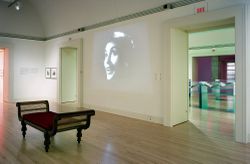
Empreintes de l’Inde démontre le rôle social, politique et anthropologique que de telles images peuvent jouer, en décrivant comment les éléments représentés ont jeté les fondements historiques – réels ou souhaités – sur lesquels un empire, plutôt qu’un assemblage de comptoirs coloniaux, a pu être bâti. Articulée autour de six thèmes, l’exposition explore des plus grands(...)
Empreintes de l’Inde démontre le rôle social, politique et anthropologique que de telles images peuvent jouer, en décrivant comment les éléments représentés ont jeté les fondements historiques – réels ou souhaités – sur lesquels un empire, plutôt qu’un assemblage de comptoirs coloniaux, a pu être bâti. Articulée autour de six thèmes, l’exposition explore des plus grands(...)
Localisation:
Salles principales
Salles principales
Date:
15 mai 2003 au 14 septembre 2003
15 mai 2003 au 14 septembre 2003
Titre:
Empreintes de l’Inde : photographie, architecture et politiques de la représentation
Actions:
Description:
Empreintes de l’Inde démontre le rôle social, politique et anthropologique que de telles images peuvent jouer, en décrivant comment les éléments représentés ont jeté les fondements historiques – réels ou souhaités – sur lesquels un empire, plutôt qu’un assemblage de comptoirs coloniaux, a pu être bâti. Articulée autour de six thèmes, l’exposition explore des plus grands(...)
Empreintes de l’Inde : photographie, architecture et politiques de la représentation
Actions:
Description:
Empreintes de l’Inde démontre le rôle social, politique et anthropologique que de telles images peuvent jouer, en décrivant comment les éléments représentés ont jeté les fondements historiques – réels ou souhaités – sur lesquels un empire, plutôt qu’un assemblage de comptoirs coloniaux, a pu être bâti. Articulée autour de six thèmes, l’exposition explore des plus grands(...)
Classification:
expositions
expositions
Date:
15 mai 2003 au
14 septembre 2003
15 mai 2003 au
14 septembre 2003
Localisation:
Salles principales
Salles principales
Classification:
photographies
photographies
Numéro de référence:
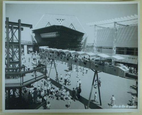
ARCH255878
ARCH255878
Personnes et institutions:
Date:
1967
1967
Classification:
photographies
photographies
Date:
1967
1967
Personnes et institutions:
Niveau de description archivistique:
Projet
Projet
Numéro de référence:
AP143.S4.D14
Description:
File documents an executed project for House VI, a weekend/vacation house designed for Richard and Suzanne Frank for a six-acre lot at Great Hollow Road, Cornwall, Connecticut. The file also includes material for renovations to House VI undertaken in 1983, 1986, and 1989-1990. Material in this file was produced between 1971 and 1989. The 1,500 square foot plan of House VI comprises a kitchen, dining room, living room and study on the ground floor, and a bedroom and bathroom on the second floor. The most notable formal and compositional ambiguities of House VI are the two staircases, one green, and the other red and positioned on the ceiling. Documents include drawings by Eisenman concerning the geometric operations at the origin of House VI (DR1994:0134:055-067), conceptual drawings (DR1994:0134:001-068; DR1994:0134:086-130; DR1994:0134:131-160), numerous colour studies of the elevations (DR1994:0134:262-343), a presentation panel (DR1994:0134:521) notes (DR1994:0134:779-782), and a first set of working drawings and "check set," completed on 30 Aug. 1973, (DR1994:0134:667-689). Documents also include drawings for major revisions which occurred from 3 October 1973 through August 1974, photocopies of photographs of the house under construction (DR1994:0134:783-805), and a copy of the site survey (DR1994:0134:806). Planned and executed renovations to House VI began in 1983. Documents relating to unexecuted renovations and additions of 1983 includes drawings (DR1994:0134:604-615), a "bid set" and annotated copies (DR1994:0134:552 and DR1994:0134:554-570; copies: DR1994:0134:646-655), and a photocopy of the site plan indicating Eisenman's initial ideas (DR1994:0134:224). Documents relating to unexecuted renovations and additions of 1986 includes seven drawings (DR1994:0134:553 and DR1994:0134:628-633). House VI was extensively rebuilt between 1988 and 1990. The renovations included the replacement of the exterior plywood walls, the insertion of steel reinforcement, a new roof with skylights, the replacement of the original stucco by a coat of Finestone, the repainting of the interior, and the addition of a plexiglas barrier to the staircase. Documents relating to the renovations of 1988-90 include original and photocopied detail drawings, an interior paint schedule by Eisenman's office, correspondence, original and photocopied technical literature, an incomplete copy of the specifications, and a copy of the original survey map (identical to DR1994:0134:806). There are also numerous photographs of the building before, during and after renovation, one photograph of presentation axonometrics for House VI, and one photograph of Eisenman's office. Documents relating to a publication on House VI include: notes (DR1994:0134:807-853), the book mock-up (DR1994:0134:854-855), and fragments of the original coloured transformation diagrams (DR1994:0134:530-531). File contains conceptual drawings, including plans, axonometrics, and sections - many black felt-tip pen and/or coloured felt-tip pen on tracing paper; and reprographic copies - mostly photocopies on wove paper. Design development drawings include site plans, plans, elevations, sections, and axonometrics - some graphite and/or coloured pencil on tracing paper and some pen and black ink and/or graphite on tracing vellum; and reprographic copies - some photocopies on wove paper and some sepia prints on mylar. Schematic drawings include site plans, plans, elevations, and sections - all pen and black ink on mylar; and reprographic copies - many blackline prints on wove paper. Working drawings include site plans, plans, elevations, sections, electrical drawings, HVAC drawings, structural drawings, and detail drawings - some coloured pencil on blueline prints on wove paper; and reprographic copies - mostly blueline prints on wove paper. Presentation drawings include plans, elevations, and axonometrics - some pen and black ink and/or transparent coloured adhesive film on mylar and some translucent adhesive coloured film on cardboard; and reprographic copies - mostly photocopies on wove paper. Model includes one finished model - grey, white, and silver paint on wood and Fome-Cor with plastic sheets. Notes and documents include manuscripts - mostly black felt-tip pen on wove paper; reprographic copies - mostly photocopies on wove paper; and a land surveyor plan - one blueline print on wove paper. Book project includes layout drawings - some black felt-tip pen on ruled paper; reprographic copies - all photocopies on wove paper; manuscripts - mostly black felt-tip pen on wove or ruled paper; one sample piece of grey cardboard used as backing for some of the presentation drawings; and sets of drawings in the form of book dummies - mostly pen and coloured ink and/or black felt-tip pen on photocopies on wove paper. Detail drawings include elevations, sections, details - mostly graphite on tracing paper. The linear cm of documents includes sets, reprographic copies and manuscripts. Notes and documents include elevations, sections, and details - some graphite on photocopies on wove paper; two sets of drawing copies, some with changes - mostly photocopies on wove paper; reprographic copies - mostly photocopies on wove paper; manuscripts - many graphite on wove paper; ephemera includes trade pamphlets; and photographs include colour images of House X prior to and during one of the renovations.
AP143.S4.D14
Description:
File documents an executed project for House VI, a weekend/vacation house designed for Richard and Suzanne Frank for a six-acre lot at Great Hollow Road, Cornwall, Connecticut. The file also includes material for renovations to House VI undertaken in 1983, 1986, and 1989-1990. Material in this file was produced between 1971 and 1989. The 1,500 square foot plan of House VI comprises a kitchen, dining room, living room and study on the ground floor, and a bedroom and bathroom on the second floor. The most notable formal and compositional ambiguities of House VI are the two staircases, one green, and the other red and positioned on the ceiling. Documents include drawings by Eisenman concerning the geometric operations at the origin of House VI (DR1994:0134:055-067), conceptual drawings (DR1994:0134:001-068; DR1994:0134:086-130; DR1994:0134:131-160), numerous colour studies of the elevations (DR1994:0134:262-343), a presentation panel (DR1994:0134:521) notes (DR1994:0134:779-782), and a first set of working drawings and "check set," completed on 30 Aug. 1973, (DR1994:0134:667-689). Documents also include drawings for major revisions which occurred from 3 October 1973 through August 1974, photocopies of photographs of the house under construction (DR1994:0134:783-805), and a copy of the site survey (DR1994:0134:806). Planned and executed renovations to House VI began in 1983. Documents relating to unexecuted renovations and additions of 1983 includes drawings (DR1994:0134:604-615), a "bid set" and annotated copies (DR1994:0134:552 and DR1994:0134:554-570; copies: DR1994:0134:646-655), and a photocopy of the site plan indicating Eisenman's initial ideas (DR1994:0134:224). Documents relating to unexecuted renovations and additions of 1986 includes seven drawings (DR1994:0134:553 and DR1994:0134:628-633). House VI was extensively rebuilt between 1988 and 1990. The renovations included the replacement of the exterior plywood walls, the insertion of steel reinforcement, a new roof with skylights, the replacement of the original stucco by a coat of Finestone, the repainting of the interior, and the addition of a plexiglas barrier to the staircase. Documents relating to the renovations of 1988-90 include original and photocopied detail drawings, an interior paint schedule by Eisenman's office, correspondence, original and photocopied technical literature, an incomplete copy of the specifications, and a copy of the original survey map (identical to DR1994:0134:806). There are also numerous photographs of the building before, during and after renovation, one photograph of presentation axonometrics for House VI, and one photograph of Eisenman's office. Documents relating to a publication on House VI include: notes (DR1994:0134:807-853), the book mock-up (DR1994:0134:854-855), and fragments of the original coloured transformation diagrams (DR1994:0134:530-531). File contains conceptual drawings, including plans, axonometrics, and sections - many black felt-tip pen and/or coloured felt-tip pen on tracing paper; and reprographic copies - mostly photocopies on wove paper. Design development drawings include site plans, plans, elevations, sections, and axonometrics - some graphite and/or coloured pencil on tracing paper and some pen and black ink and/or graphite on tracing vellum; and reprographic copies - some photocopies on wove paper and some sepia prints on mylar. Schematic drawings include site plans, plans, elevations, and sections - all pen and black ink on mylar; and reprographic copies - many blackline prints on wove paper. Working drawings include site plans, plans, elevations, sections, electrical drawings, HVAC drawings, structural drawings, and detail drawings - some coloured pencil on blueline prints on wove paper; and reprographic copies - mostly blueline prints on wove paper. Presentation drawings include plans, elevations, and axonometrics - some pen and black ink and/or transparent coloured adhesive film on mylar and some translucent adhesive coloured film on cardboard; and reprographic copies - mostly photocopies on wove paper. Model includes one finished model - grey, white, and silver paint on wood and Fome-Cor with plastic sheets. Notes and documents include manuscripts - mostly black felt-tip pen on wove paper; reprographic copies - mostly photocopies on wove paper; and a land surveyor plan - one blueline print on wove paper. Book project includes layout drawings - some black felt-tip pen on ruled paper; reprographic copies - all photocopies on wove paper; manuscripts - mostly black felt-tip pen on wove or ruled paper; one sample piece of grey cardboard used as backing for some of the presentation drawings; and sets of drawings in the form of book dummies - mostly pen and coloured ink and/or black felt-tip pen on photocopies on wove paper. Detail drawings include elevations, sections, details - mostly graphite on tracing paper. The linear cm of documents includes sets, reprographic copies and manuscripts. Notes and documents include elevations, sections, and details - some graphite on photocopies on wove paper; two sets of drawing copies, some with changes - mostly photocopies on wove paper; reprographic copies - mostly photocopies on wove paper; manuscripts - many graphite on wove paper; ephemera includes trade pamphlets; and photographs include colour images of House X prior to and during one of the renovations.
Personnes et institutions:
Date:
1971-1989
1971-1989
Titre:
House VI, Cornwall, Connecticut
Actions:
AP143.S4.D14
Description:
File documents an executed project for House VI, a weekend/vacation house designed for Richard and Suzanne Frank for a six-acre lot at Great Hollow Road, Cornwall, Connecticut. The file also includes material for renovations to House VI undertaken in 1983, 1986, and 1989-1990. Material in this file was produced between 1971 and 1989. The 1,500 square foot plan of House VI comprises a kitchen, dining room, living room and study on the ground floor, and a bedroom and bathroom on the second floor. The most notable formal and compositional ambiguities of House VI are the two staircases, one green, and the other red and positioned on the ceiling. Documents include drawings by Eisenman concerning the geometric operations at the origin of House VI (DR1994:0134:055-067), conceptual drawings (DR1994:0134:001-068; DR1994:0134:086-130; DR1994:0134:131-160), numerous colour studies of the elevations (DR1994:0134:262-343), a presentation panel (DR1994:0134:521) notes (DR1994:0134:779-782), and a first set of working drawings and "check set," completed on 30 Aug. 1973, (DR1994:0134:667-689). Documents also include drawings for major revisions which occurred from 3 October 1973 through August 1974, photocopies of photographs of the house under construction (DR1994:0134:783-805), and a copy of the site survey (DR1994:0134:806). Planned and executed renovations to House VI began in 1983. Documents relating to unexecuted renovations and additions of 1983 includes drawings (DR1994:0134:604-615), a "bid set" and annotated copies (DR1994:0134:552 and DR1994:0134:554-570; copies: DR1994:0134:646-655), and a photocopy of the site plan indicating Eisenman's initial ideas (DR1994:0134:224). Documents relating to unexecuted renovations and additions of 1986 includes seven drawings (DR1994:0134:553 and DR1994:0134:628-633). House VI was extensively rebuilt between 1988 and 1990. The renovations included the replacement of the exterior plywood walls, the insertion of steel reinforcement, a new roof with skylights, the replacement of the original stucco by a coat of Finestone, the repainting of the interior, and the addition of a plexiglas barrier to the staircase. Documents relating to the renovations of 1988-90 include original and photocopied detail drawings, an interior paint schedule by Eisenman's office, correspondence, original and photocopied technical literature, an incomplete copy of the specifications, and a copy of the original survey map (identical to DR1994:0134:806). There are also numerous photographs of the building before, during and after renovation, one photograph of presentation axonometrics for House VI, and one photograph of Eisenman's office. Documents relating to a publication on House VI include: notes (DR1994:0134:807-853), the book mock-up (DR1994:0134:854-855), and fragments of the original coloured transformation diagrams (DR1994:0134:530-531). File contains conceptual drawings, including plans, axonometrics, and sections - many black felt-tip pen and/or coloured felt-tip pen on tracing paper; and reprographic copies - mostly photocopies on wove paper. Design development drawings include site plans, plans, elevations, sections, and axonometrics - some graphite and/or coloured pencil on tracing paper and some pen and black ink and/or graphite on tracing vellum; and reprographic copies - some photocopies on wove paper and some sepia prints on mylar. Schematic drawings include site plans, plans, elevations, and sections - all pen and black ink on mylar; and reprographic copies - many blackline prints on wove paper. Working drawings include site plans, plans, elevations, sections, electrical drawings, HVAC drawings, structural drawings, and detail drawings - some coloured pencil on blueline prints on wove paper; and reprographic copies - mostly blueline prints on wove paper. Presentation drawings include plans, elevations, and axonometrics - some pen and black ink and/or transparent coloured adhesive film on mylar and some translucent adhesive coloured film on cardboard; and reprographic copies - mostly photocopies on wove paper. Model includes one finished model - grey, white, and silver paint on wood and Fome-Cor with plastic sheets. Notes and documents include manuscripts - mostly black felt-tip pen on wove paper; reprographic copies - mostly photocopies on wove paper; and a land surveyor plan - one blueline print on wove paper. Book project includes layout drawings - some black felt-tip pen on ruled paper; reprographic copies - all photocopies on wove paper; manuscripts - mostly black felt-tip pen on wove or ruled paper; one sample piece of grey cardboard used as backing for some of the presentation drawings; and sets of drawings in the form of book dummies - mostly pen and coloured ink and/or black felt-tip pen on photocopies on wove paper. Detail drawings include elevations, sections, details - mostly graphite on tracing paper. The linear cm of documents includes sets, reprographic copies and manuscripts. Notes and documents include elevations, sections, and details - some graphite on photocopies on wove paper; two sets of drawing copies, some with changes - mostly photocopies on wove paper; reprographic copies - mostly photocopies on wove paper; manuscripts - many graphite on wove paper; ephemera includes trade pamphlets; and photographs include colour images of House X prior to and during one of the renovations.
House VI, Cornwall, Connecticut
Actions:
AP143.S4.D14
Description:
File documents an executed project for House VI, a weekend/vacation house designed for Richard and Suzanne Frank for a six-acre lot at Great Hollow Road, Cornwall, Connecticut. The file also includes material for renovations to House VI undertaken in 1983, 1986, and 1989-1990. Material in this file was produced between 1971 and 1989. The 1,500 square foot plan of House VI comprises a kitchen, dining room, living room and study on the ground floor, and a bedroom and bathroom on the second floor. The most notable formal and compositional ambiguities of House VI are the two staircases, one green, and the other red and positioned on the ceiling. Documents include drawings by Eisenman concerning the geometric operations at the origin of House VI (DR1994:0134:055-067), conceptual drawings (DR1994:0134:001-068; DR1994:0134:086-130; DR1994:0134:131-160), numerous colour studies of the elevations (DR1994:0134:262-343), a presentation panel (DR1994:0134:521) notes (DR1994:0134:779-782), and a first set of working drawings and "check set," completed on 30 Aug. 1973, (DR1994:0134:667-689). Documents also include drawings for major revisions which occurred from 3 October 1973 through August 1974, photocopies of photographs of the house under construction (DR1994:0134:783-805), and a copy of the site survey (DR1994:0134:806). Planned and executed renovations to House VI began in 1983. Documents relating to unexecuted renovations and additions of 1983 includes drawings (DR1994:0134:604-615), a "bid set" and annotated copies (DR1994:0134:552 and DR1994:0134:554-570; copies: DR1994:0134:646-655), and a photocopy of the site plan indicating Eisenman's initial ideas (DR1994:0134:224). Documents relating to unexecuted renovations and additions of 1986 includes seven drawings (DR1994:0134:553 and DR1994:0134:628-633). House VI was extensively rebuilt between 1988 and 1990. The renovations included the replacement of the exterior plywood walls, the insertion of steel reinforcement, a new roof with skylights, the replacement of the original stucco by a coat of Finestone, the repainting of the interior, and the addition of a plexiglas barrier to the staircase. Documents relating to the renovations of 1988-90 include original and photocopied detail drawings, an interior paint schedule by Eisenman's office, correspondence, original and photocopied technical literature, an incomplete copy of the specifications, and a copy of the original survey map (identical to DR1994:0134:806). There are also numerous photographs of the building before, during and after renovation, one photograph of presentation axonometrics for House VI, and one photograph of Eisenman's office. Documents relating to a publication on House VI include: notes (DR1994:0134:807-853), the book mock-up (DR1994:0134:854-855), and fragments of the original coloured transformation diagrams (DR1994:0134:530-531). File contains conceptual drawings, including plans, axonometrics, and sections - many black felt-tip pen and/or coloured felt-tip pen on tracing paper; and reprographic copies - mostly photocopies on wove paper. Design development drawings include site plans, plans, elevations, sections, and axonometrics - some graphite and/or coloured pencil on tracing paper and some pen and black ink and/or graphite on tracing vellum; and reprographic copies - some photocopies on wove paper and some sepia prints on mylar. Schematic drawings include site plans, plans, elevations, and sections - all pen and black ink on mylar; and reprographic copies - many blackline prints on wove paper. Working drawings include site plans, plans, elevations, sections, electrical drawings, HVAC drawings, structural drawings, and detail drawings - some coloured pencil on blueline prints on wove paper; and reprographic copies - mostly blueline prints on wove paper. Presentation drawings include plans, elevations, and axonometrics - some pen and black ink and/or transparent coloured adhesive film on mylar and some translucent adhesive coloured film on cardboard; and reprographic copies - mostly photocopies on wove paper. Model includes one finished model - grey, white, and silver paint on wood and Fome-Cor with plastic sheets. Notes and documents include manuscripts - mostly black felt-tip pen on wove paper; reprographic copies - mostly photocopies on wove paper; and a land surveyor plan - one blueline print on wove paper. Book project includes layout drawings - some black felt-tip pen on ruled paper; reprographic copies - all photocopies on wove paper; manuscripts - mostly black felt-tip pen on wove or ruled paper; one sample piece of grey cardboard used as backing for some of the presentation drawings; and sets of drawings in the form of book dummies - mostly pen and coloured ink and/or black felt-tip pen on photocopies on wove paper. Detail drawings include elevations, sections, details - mostly graphite on tracing paper. The linear cm of documents includes sets, reprographic copies and manuscripts. Notes and documents include elevations, sections, and details - some graphite on photocopies on wove paper; two sets of drawing copies, some with changes - mostly photocopies on wove paper; reprographic copies - mostly photocopies on wove paper; manuscripts - many graphite on wove paper; ephemera includes trade pamphlets; and photographs include colour images of House X prior to and during one of the renovations.
Niveau de description archivistique:
File 14
File 14
Date:
1971-1989
1971-1989
Personnes et institutions:
Classification:
articles
articles
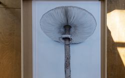
Titre:
Nouveau documentaire
Nouveau documentaire
Actions:
Takashi Homma en conversation avec Stefano Graziani et Bas Princen
Mot(s)-clé(s):
La vie des documents, la photographie en tant que projet, Stefano Graziani et Bas Princen, Takashi Homma, conversation, histoire orale, vagues, champignons
La vie des documents, la photographie en tant que projet, Stefano Graziani et Bas Princen, Takashi Homma, conversation, histoire orale, vagues, champignons
Publié:
15 mai 2023
15 mai 2023
Titre:
Nouveau documentaire
Takashi Homma en conversation avec Stefano Graziani et Bas Princen
Actions:
Nouveau documentaire
Takashi Homma en conversation avec Stefano Graziani et Bas Princen
Actions:
Classification:
expositions
expositions

Actions:
Description:
Au cours des années soixante, les profondes transformations de Montréal en ont fait un archétype des grandes métropoles occidentales. À titre d’hôte de l’exposition universelle de 1967, Montréal a confirmé son statut de ville de l’avenir sur la scène internationale. Les années 60 : Montréal voit grand illustre les processus qui ont entraîné cette mutation. À travers des(...)
Au cours des années soixante, les profondes transformations de Montréal en ont fait un archétype des grandes métropoles occidentales. À titre d’hôte de l’exposition universelle de 1967, Montréal a confirmé son statut de ville de l’avenir sur la scène internationale. Les années 60 : Montréal voit grand illustre les processus qui ont entraîné cette mutation. À travers des(...)
Localisation:
Salles principales
Salles principales
Date:
20 octobre 2004 au 11 septembre 2005
20 octobre 2004 au 11 septembre 2005
Titre:
Les années 60 : Montréal voit grand
Actions:
Description:
Au cours des années soixante, les profondes transformations de Montréal en ont fait un archétype des grandes métropoles occidentales. À titre d’hôte de l’exposition universelle de 1967, Montréal a confirmé son statut de ville de l’avenir sur la scène internationale. Les années 60 : Montréal voit grand illustre les processus qui ont entraîné cette mutation. À travers des(...)
Les années 60 : Montréal voit grand
Actions:
Description:
Au cours des années soixante, les profondes transformations de Montréal en ont fait un archétype des grandes métropoles occidentales. À titre d’hôte de l’exposition universelle de 1967, Montréal a confirmé son statut de ville de l’avenir sur la scène internationale. Les années 60 : Montréal voit grand illustre les processus qui ont entraîné cette mutation. À travers des(...)
Classification:
expositions
expositions
Date:
20 octobre 2004 au
11 septembre 2005
20 octobre 2004 au
11 septembre 2005
Localisation:
Salles principales
Salles principales


